DESIGN AND FABRICATION OF BALL FEEDER MECHANISM AND BODY FOR TENNIS BALL MACHINE
MOHD HAFISZUDIN BIN AHMAD
i
SUPERVISOR DECLARATION
“I hereby declare that I have read this thesis and in my opinion this report is sufficient in terms of scope and quality for the award of the degree of Bachelor of
Mechanical Engineering (Automotive)”
Singature: ………..
Supervisor: ………..
ii
DESIGN AND FABRICATION OF BALL FEEDER MECHANISM AND BODY FOR TENNIS BALL MACHINE
MOHD HAFISZUDIN BIN AHMAD
This technical report is submitted in accordance with the requirements of the Bachelor of Mechanical Engineering (Automotive)
Faculty of Mechanical Engineering Universiti Teknikal Malaysia Melaka
iii
DECLARATION
“I hereby declare that the work in this report is my own except for the summaries and quotations which have been duly acknowledge.”
Singature: ………..
Author: ………..
iv
DEDICATION
v
ACKNOWLEDGEMENT
First and foremost, I am grateful to God because give me opportunity and healthy to complete this final year project. I have taken more efforts in this project. However, it would not been possible without the support and help of many people. I would like express my appreciation to my supervisor, Mr Herdy Rusnandi who has been guidance and support to me during doing the final year project. His willingness to motivate me contributed tremendously to my project.
I would to thanks to the staff and technician at Faculty of Mechanical Engineering, Universiti Teknikal Malaysia Melaka (UTeM) for their help during this project. They are all willing to help and contribute their time to me in order to conduct the project. Deepest gratitude are also due to the evaluator which evaluate me during final year project presentation.
vi
ABSTRACT
vii
ABSTRAK
viii
TABLE OF CONTENT
CHAPTER TITLE PAGES
SUPERVISOR DECLARATION i
DECLARATION iii
DEDICATION iv
ACKNOWLEDGEMENT v
ABSTRACT vi
ABSTRAK vii
TABLE OF CONTENT viii
LIST OF TABLE x
LIST OF FIGURE xi
LIST OF SYMBOLS xiii
LIST OF APPENDIX xiv
CHAPTER 1 INTRODUCTION 1
1.1 OVERVIEW 1
1.2 PROBLEM STATEMENT 2
1.3 OBJECTIVE 3
1.4 SCOPE 3
1.5 PROJECT OVERVIEW 3
CHAPTER 2 LITERATURE REVIEW 4
2.1 MECHANISMOF TENNIS BALL MACHINE 4
2.2 BALL FEEDER MECHANISM 5
2.2. ENGINEERING DESIGN 7
ix
CHAPTER 3 METHODOLOGY 10
3.1 INTRODUCTION 10
3.2 PROJECT DEVELOPMNT PROCESS 11 3.2.1 Identifying The Problem 12 3.2.2 Technical Specification 12 3.2.3 Concept Design 15 3.2.4 Fabrication 18
CHAPTER 4 RESULT AND ANALYSIS 22
4.1 INTRODUCTION 22
4.2 BODY FOR TENNIS BALL MACHINE 22
4.2.1 Fabrication 22
4.3 BALL FEEDER MECHANISM 26
4.3.1 Ball Container 26
4.3.2 Rotating Plate 29
4.3.3 Ball Path 31
4.3.4 Tennis Ball Machine 34
CHAPTER 5 DISCUSSION 39
CHAPTER 6 CONCLUSION 42
6.1 Conclusion 42
6.2 Recommendation 43
REFERENCES 44
BIBLIOGRAPHY 45
x
LIST OF TABLE
No Title Pages
2.3 The Different Between Pneumatic and Mecahnical Tennis Ball
Launcher .(Source : Wojcicki et al. 2011) 4-5
xi
LIST OF FIGURE
No Title Pages
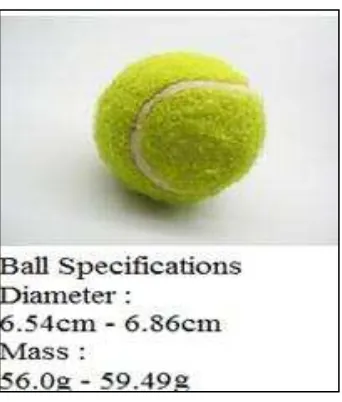
2.2(a) Ball Specification
(Source : International Tennis Federation (2012)) 6 2.2(b) The Ball Feeder Mechanism
(Source : Kenneth M.Hodges (1980)) 6
2.3(a) Engineering Design Process
(Source : George E.Dieter and Linda Schmidt (2009)) 7 2.3(b) Pugh Concept Method
(Source : Ann Hopkins (2012)) 8
2.4 The Example of Drawing Product Using Catia Software
(Source : idexsolutions) 9
3.2 The Flow Chart for PSM 1 and PSM 2 11
3.22(a) Motor 13
3.22(b) Tachometer 13
3.22(c) The Roller 14
3.22(d) The Angle Bar with Hole 14
3.22(e) The Metal Sheet 15
3.2.3(a) Concept Design A 16
3.2.3(B) Concept Design B 17
xii
4.2.1(a) Angle Bar 23
4.2.1(b) Body Frame Using Catia 23
4.2.1(c) Marking Process 24
4.2.1(d) High Speed Cutting Machine 24
4.2.1(e) Joining Process Using Screw and Nut 25
4.2.1(f) Body Frame 25
4.3.1(a) Plastic Bottle 26
4.3.1(b) Ball Container After Modified 27
4.3.1(c) Ball Container Using Catia 27
4.3.1(d) Ball Container Attached To The Body Frame 28
4.3.2(a) Rotating Plate Using Catia 29
4.3.2(b) Rotating Plate With Motor 30
4.3.2(c) Rotating Plate At Body Frame 30
4.3.3(a) Ball Path Using Catia 31
4.3.3(b) Cutting Process by Shearing Machine 32
4.3.3(c) Bending Process by Bending Machine 32
4.3.3(d) Ball Path at Body Frame 33
4.3.3(e) Stand Holder to Hold Ball Path 33
4.3.4(a) Tennis Ball Machine 34
4.3.4(b) Tennis Ball Machine 34
4.3.4(c) Tennis Ball Machine 35
4.3.4(d) Tennis Ball Machine 35
4.3.4(e) Tennis Ball Machine 36
xiii
LIST OF SYMBOLS
d = diameter
m = meter
° = degree angle
θ = angle
kg = kilogram
g = gram
xiv
LIST OF APPENDIX
No. Title Pages
A Flow Chart 46
B Gantt Chart 47
C List of Materials and Cost production 48
CHAPTER 1
INTRODUCTION
1.1 OVERVIEW
Tennis ball machine is one of the device or mechanism of the machine that use by the people to training and playing tennis. Nowadays tennis becomes one of the famous sports in the world and the amount of people that want to involve in this kind of sport is increasingly over the time. Generally, tennis ball machine is the machine that launches the ball tennis using the man power. In specific, tennis ball machine consists of ball storage mechanism, feeder mechanism, serving mechanism, control circuit and body frame of the tennis ball machine. (Source : Liang,H et al 2012).
2
comparing the pneumatic tennis ball machine. The pneumatic tennis ball machine is suitable for the beginners in the tennis profession.(Source : Wojcicki.K et al. 2011) The basic principle for this machine to operate is from the ball storage. The ball storage is where the ball is keep and placed before its ready to launch. Before the ball is launch, it will go through the supply or feeder mechanism. The feeder mechanism is the mechanism that passed the ball at certain time interval from the ball storage to the launcher mechanism. The launcher will launch the tennis ball at certain velocity to the user. This tennis ball machine will help the people or player that want to practice or improve their skill in playing tennis without using other partner or coach.
1.2 PROBLEM STATEMENTS
In Malaysia, tennis sport begins to grow rapidly and get serious attention by the public especially tennis player. Therefore, coach is needed to train and teach how to play tennis properly. Unfortunately, the coach that can train and teach to play tennis is smaller. It makes the people or the beginner that want to play tennis lack of suitable opportunities to practice without proper training partner. In this case, apart from using the service of a coach, a person can practice in playing tennis by using tennis ball machine.
3
1.3 OBJECTIVES
The objectives of this project are to design the prototype of feeder mechanism and body for tennis ball machine. Furthermore, fabricate the feeder mechanism and body for tennis ball machine. The next objective is to produce a tennis ball machine with low cost.
1.4 SCOPE
The scope of this project is to study and analysis the mechanism of ball feeder for tennis ball machine. Furthermore, design and fabricate the prototype of ball feeder mechanism and the body for tennis ball machine. The other scope in this project is use the design software such as CATIA V520 and other software in order to design and analyzing a ball feeder mechanism and the body of tennis ball machine
1.5 PROJECT OVERVIEW
4
CHAPTER 2
LITERATURE REVIEW
2.1 MECHANISM OF TENNIS BALL MACHINE
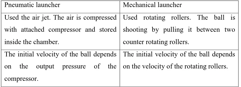
[image:19.595.124.534.618.766.2]In the market today, there have may type of the tennis ball machine. The variety of the tennis ball machine includes the type of mechanism, price, and design of the body frame of the tennis ball machine. The main difference between tennis ball machines are the number of controlled parameters and possible range of their adjusting. .(Source : Wojcicki.K et al. 2011). Generally, the tennis ball launcher can be divided into two groups mechanism. First is the pneumatic tennis ball launcher. The machine is using compressed air as a mechanism to launch the ball. Second is the mechanical tennis ball launcher. The machine is using rotating rollers or wheels to launch the ball. They have many different between pneumatic ball launcher and mechanical ball launcher. Table 2.1 shows the different between pneumatic tennis ball launcher and mechanical tennis ball launcher.
Table 2.1 The Different Between Pneumatic and Mechanical Tennis Ball Launcher
Pneumatic launcher Mechanical launcher
Used the air jet. The air is compressed with attached compressor and stored inside the chamber.
Used rotating rollers. The ball is shooting by pulling it between two counter rotating rollers.
The initial velocity of the ball depends on the output pressure of the compressor.
5
Elevation and heading angles can be adjusted by setting the outlet tube.
Elevation and heading angles can be changed by turning the whole machine or launcher mechanism.
Allow one to practice basic stroke and cannot be used for advanced training.
Allow one to practice more advanced training.
.(Source : Wojcicki.K et al. 2011)
2.2 BALL FEEDER MECHANISM
Ball feeder mechanism in tennis ball machine is the one mechanism that supplied or transfers the tennis ball to the launcher mechanism. The feeder mechanism will make the tennis ball pass through the mechanism from the ball storage. A tennis ball server supplied by a motorized ball feeder comprised of a trough and rotating plate that feeds balls at one rate. (Source : Hodges K. M(1977)) For example one ball serves every three or four seconds. This is to make sure the ball pass through the ball launcher is easily and orderly manner without any problem such as the tennis ball is stuck from going the ball launcher.
6
Figure 2.2(a): Ball Specification
( Source:International Tennis Federation (2012) )
[image:21.595.240.411.52.253.2] [image:21.595.168.488.340.675.2]7
2.3 ENGINEERING DESIGN
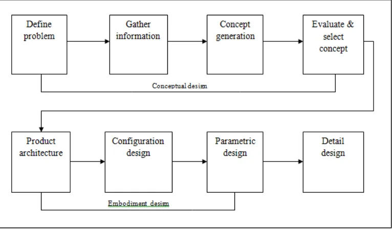
In engineering design consist of engineering design process. This design process can be used to achieve several different outcomes. Any project or work that needs to design and produce something must follow the engineering design process. The design process should be conducted so as to develop quality, cost competitive products in the shortest time possible. (Source : Dieter G. E and Schmidt L.C (2009)).. In engineering design, they have several types of design which are original design, Adaptive design, Redesign, Selection design and Industrial design. Engineering design process consist eight steps of design activities. (Source : Dieter G. E and Schmidt L.C (2009)).. Figure 2.3 shows the engineering design process.
Figure 2.3(a) Engineering Design Process (Source : Dieter G. E and Schmidt L.C (2009)).
[image:22.595.147.530.347.571.2]8
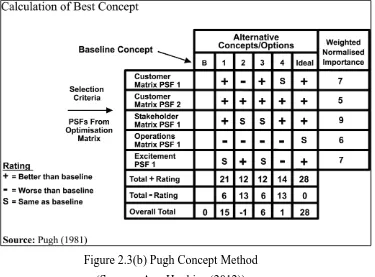
methods for selection concept design. First is Comparison Based on Absolute Criteria. Second is Pugh Concept Selection Method. Third is Measurement Scales. Fourth is Weighted Decision Matrix and fifth is Analytic Hierarchy Process (AHP). (Source : Dieter G. E and Schmidt L.C (2009)).
Pugh concept selection method is the method that compares each concept relative to a reference or datum concept. The criterion determines whether the concept is better than, poorer than or same as the reference concept. They have eight steps in Pugh concept selection method. First step is choosing the criteria by which the concepts will be evaluated. The next step is formulating the decision matrix. Then, clarify the design concepts. Next is choosing the datum concept. Then, run the matrix. The next step is evaluating the ratings. Next is establishing a new datum and rerun the matrix and the last step is examine the selected concept for improvement opportunities. (Source : Dieter G. E and Schmidt L.C (2009)). Figure 2.3(b) show the pugh concept method.
[image:23.595.148.523.418.695.2]9
2.4 COMPUTER AIDED DESIGN(CAD)
Computer Aided Design is tools in engineering design that had been develop for a long time ago. Computer Aided Design become more advanced over the time and become a critical enabling technology in product design since they help build virtual prototypes of complex products like automobiles, airplanes and electronic appliances. The CAD can make the design process become more flexible and easy to conduct. Furthermore, the CAD also can be used to do a simulation on the design product.
Today, CAD enabled design engineer select available materials from databases to realize desired product functionality. They have many types of CAD software in the market like CATIA (Computer Aided Three Dimensional Interactive Application), AutoCAD, BrisCAD, Solid Work, AutoDesk, ADAMS (Automatic Dynamic Analysis of Mechanical System) and other CAD software. All this kind of software will help the design process, design engineer to design the product and do simulation analysis on the product. Figure 2.4 show the drawing product using CATIA software.