UNIVERSITI TEKNIKAL MALAYSIA MELAKA
LASER MACHINING OF WASTE PLASTIC PRODUCTS
This report submitted in accordance with the requirements of the Universiti Teknikal Malaysia Melaka (UTeM) for the Bachelors of
Manufacturing Engineering (Honors) (Manufacturing Process)
by
MOHD SYAZMAN BIN JAAFAR
B051010189
890929045089
UNIVERSITI TEKNIKAL MALAYSIA MELAKA
BORANG PENGESAHAN STATUS LAPORAN PROJEK SARJANA MUDA
TAJUK: LASER MACHINING OF WASTE PLASTIC PRODUCTS
SESI PENGAJIAN: 2012/13 Semester 2
Saya MOHD SYAZMAN BIN JAAFAR
mengaku membenarkan Laporan PSM ini disimpan di Perpustakaan Universiti Teknikal Malaysia Melaka (UTeM) dengan syarat-syarat kegunaan seperti berikut:
1. Laporan PSM adalah hak milik Universiti Teknikal Malaysia Melaka dan penulis. 2. Perpustakaan Universiti Teknikal Malaysia Melaka dibenarkan membuat salinan
untuk tujuan pengajian sahaja dengan izin penulis.
3. Perpustakaan dibenarkan membuat salinan laporan PSM ini sebagai bahan pertukaran antara institusi pengajian tinggi.
4. **Sila tandakan (√)
(Mengandungi maklumat yang berdarjah keselamatan atau kepentingan Malaysiasebagaimana yang termaktub dalam AKTA RAHSIA RASMI 1972)
DECLARATION
I hereby, declared this report entitled “Laser Machining of Waste Plastic Products” is the
results of my own research except as cited in reference
.
Signature :
Author’s Name : Mohd Syazman bin Jaafar
APPROVAL
This report is submitted to the Faculty of Manufacturing Engineering of UTeM as a partial fulfillment of the fulfillment of the requirement for the degree of Bachelor of Manufactuirng Engineering Bachelor Of Manufacturing Engineering (Manufacturing Process) (Hons.). The members of the supervisory committee are as follow:
i
ABSTRACK
ii
ABSTRACT
iii
DEDICATION
iv
ACKNOWLEDGEMENTS
Bismillahirahmanirahim,
First of all, I would like to thanks Allah for His bless and let my Final Year Project (PSM) II successfully done. Then, I would like to appreciate my parents for their encouragement and support in order to finish my project.
I would like to thanks Prof Madya Dr. Ir. Sivarao in giving me guidance to complete this report and spending a lot of your time for me. Without his guidance, it is difficult and nearly impossible for me to done the project according to the objective been states. The excellent working relationship between my supervisor and me has provided me with bountiful knowledge and experience for the future. The help rendered to me is priceless, be it from the smallest of its kind to the largest.
Last and not least, my highest thankfulness is dedicated to my beloved siblings, housemate, classmate, course mate, frinds and other parties whom have helped me directly or indirectly.
v
List Abbreviations, Symbols and Nomenclatures xiii
CHAPTER 1: INTRODUCTION 1
1.5.1 Laser Material Processing 4
vi
2.1 Laser Machining on Metallic Material 48 2.2 Laser Machining on Ceramic Material 52 2.3 Laser Machining on Composite Materials 54 2.4 Laser Machining on Flexible Material 55
2.5 Laser Machining on Wood Material 56
2.6 Laser Machining on Polymer Material 59
2.6.1 Kerf Width 59
2.6.2 Cutting Depth 60
2.6.3 Surface Roughness 61
2.7 Conclusion 62
CHAPTER 3: METHODOLOGY 63
3.1 Effects of Plastics Waste 64
3.1.1 Solid Waste Definition 65
3.1.2 Solid Waste Regulation 65
3.2 Material Classification 68
3.2.1 Factors to be Consider 68
vii
3.2.3 Material Specification 68
3.2.4 Selection Method 69
3.3 Preprocess Parameter 70
3.3.1 Gathering process 71
3.3.2 Selecting and Counting Process 71
3.3.3 Washing Process 71
3.7.1 Material Preparation & Profile Drawing 80 3.7.2 Machine Startup & Material Loading 81 3.7.3 Import Program into Control Panel of Machine 82 3.7.4 Dry Run and Actual Run Cutting 82
3.7.5 Responses Measurement 83
3.8 Result and Discussion 84
viii
CHAPTER 4: RESULT AND DISCUSSION 85
4.1 Data Processing 85
4.2 Cutting Distance 85
4.2.1 Result 85
4.2.2 Effects of Process Parameters 88
4.3 Burr Height 89
4.3.1 Result 89
4.3.2 Effects of Process Parameters 91
4.4 Kerf Width 93
4.4.1 Result 93
4.4.2 Effects of Process Parameters 95
4.5 Surface Roughness 97
4.5.1 Result 97
4.5.2 Effects of Process Parameters 99
4.6 Material Application 101
CHAPTER 5: CONCLUSION AND RECOMMENDATION 102
ix
LIST OF TABLES
1.1 Gas Laser Comparisons in the Aspects of Linear Power Density, Maximum Power and Power Efficiency Percent for He-Ne,
Argon and CO2 28
1.2 Types of Assisted Gas Used in CO2 Laser Cutting 37
1.3 Cylindrical and Conical Nozzle 40
3.1 HDPE resistance and quick facts 69
3.2 Basic Specifications of the LVD Helius Hybrid 2513 Laser Cutting
Machine 74
3.3 Cutting parameters need to controlled 75 3.4 DOE Matrix for cutting engine oil container 76
4.1 Cutting distance measurement for all nine cutting lines according to
DOE 86
4.2 The details of burr height for all nine cutting lines according to DOE 89 4.3 Details of kerf width and deviation measurement values for all nine
Cutting lines according DOE 93
4.4 The details of surface roughness measurement for all nine cutting
lines according to DOE 97
x
LIST OF FIGURES
1.1 Classification of Laser Material Processing Flow Chart 5 1.2 The History of Maximum Laser Pulse Intensity throughout
the Past 50 Years 9
1.3 Simple Atom Model 15
1.4 Photon Simulation 17
1.5 Photon Amplification; Amplification States (A) Laser Off, (B&C) Initial Random States, (D) Initial Stimulation, (E)
Amplification And (F) Coherent Beam 17
1.6 Comparison of Monochromatic Light between Fluorescent
Light and Laser 18
1.7 Comparison of Coherency between Normal Light and Laser 18 1.8 Comparison of Radiance of Light Bulb and Laser Beam 19
1.9 Gas Laser Layout 20
1.10 Solid Laser Layout 23
1.11 Schematic of One, Two and Three-Dimensional Laser Machining 23
1.12 Laser through Drilling 26
1.13 Laser through Cutting 27
1.14 Laser through Grooving 28
1.15 Three-dimensional Types of Cutting Methods 29 1.16 Examples of Laser Cutting Process for Various Materials 31
1.17 Laser Cutting Head 33
1.18 Cutting Out an Edge 34
1.19 Part with Oxide-free Cut Edge 35
1.20 Vibrations of CO2 Molecules 36
1.21 The CO2 Laser System 37
xi
Affected by Material Thickness 43
1.24 Maximum Cutting Gas Consumption per Hour in Continuous Cutting for Cutting with Oxygen with Gas Pressure Up to
6 Bars 45
1.25 Maximum Cutting Gas Consumption per Hour in Continuous
Cutting with Nitrogen with Gas Pressure Up to 20 Bars 45 1.26 Power versus Time in Continuous Wave 47
1.27 Power versus Time in Gated Pulse 47
1.28 Correlation between Frequency and Surface Roughness 48 1.29 Different Types of Nozzle Design; From Left: Standard Nozzle,
Laval Nozzle and Autonomous Nozzle 49
1.30 Focal Position 50
1.31 Standoff Distance 51
1.32 Laser Drilling 56
1.33 Examples of A Trepanned Hole for Different Materials 57 1.34 Example of Percussion Drilled Hole 58 1.35 100µm Holes Drilled in 75mm High-Density Polyethylene
with; Left, A Twist Drill Bit and Right, A Kerf Laser 59
3.1 Methodology Flow chart 63
3.2 Type of Municipal Waste Composition 14 SEA and East Asian
Countries 66
3.3 Pie Chart of Malaysia Waste Composition in year 2005 67
3.4 Preprocess parameter flow chart 70
3.5 a) Free space between two layers 72
b) Sawing process 72
c) Center line of bottle 72
xii 3.9 a) The Largest Flat Area Oil Container 78
b) Dimension of Flat Area 78
c) The Specimen after Cutting Process 78
3.10 Experimental Flow Chart 79
3.11 Dimension for the DOE Sample 80
3.12 The 2D drawing for the DOE Sample 80
3.13 a) The wood jig clamp on the machine table 81 b) The DOE sample attach on the jig 81 3.14 The Digital Imaging Microscopy (DIM) 83 3.15 The Mitutoyo Portable Surface Roughness Tester SJ 301 83
4.1 The graph Power (W) and Cutting Speed (mm/min) versus Cutting
Distance (mm) 87
4.2 The graph Power (W) and Cutting Speed (mm/min) versus Burr
Height (mm) 90
4.3 The schematic image of burr height 92 4.4 The graph Power (W) and Cutting Speed (mm/min) versus Kerf
Width (mm) 94
4.5 The graph Power (W) and Cutting Speed (mm/min) versus Surface
Roughness (µm) 98
xiii
LIST OF ABBREVIATIONS, SYMBOLS AND NOMENCLATURE
Ar - Argentom gas
1
CHAPTER 1
INTRODUCTION
Generally, this chapter discussing on the project background, problem statement, scope of the project and objective of the study. All the schematic have been arranged toward a solution for the issue which been raise up.
1.1 Project Background
2 as laser machining. Therefore, this project would be used as guideline to handle the laser cutting process in order to get the excellent surface finish for joining process after that.
1.2 Problem Statement
The plastic material sheet was normally being cut using conventional cutting methods such as scissor, bandsaw, shear machine and blanking machine. The quality and accuracy issue on the cutting geometry being ignored because of the manual process. Human skills and experience became the main criteria in order to be seriously involved in the cutting plastic sheet field. The decreasing of current labor which inversely proportional with the machining cost makes the process of cutting plastic sheet was not a good business in the current situation. Besides, the limitation of machine flexibilities also contributes to the reduction of the method to cut the plastic sheet material.
1.3 Scope of Project
3
1.4 Objectives
Several objectives are outlined in these investigations which are stated below:
i. To investigate the interaction between laser beam and polyethelene (PE) material;
ii. To identify the suitable parameter processing for polyethelene (PE) material; iii. To recommend the optimum parameters for cutting the polyethelene (PE)
4
1.5 Theory
All the related fundamental information about the laser machining process are summarized here. There were several types of laser machine, parameters and responses been establish in the current technology field.
1.5.1 Laser Material Processing
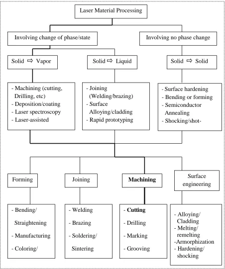
The increasing demand of laser in material processing can be attributed to several unique advantages of laser namely, high productivity, automation worthiness, non-contact processing, elimination of finishing operation, reduced processing cost, improved product quality, greater material utilization and minimum heat affected zone. Figure 1.1 shows a general classification of the laser material processing techniques. In general, application of laser to material processing can be grouped into two major classes:
(a) Applications requiring limited energy/power and causing no significant change of phase or state;
(b) Applications requiring substantial amount of energy to induce the phase transformations.
For the second category, laser power/efficiency and interaction-time is crucial as the processes involve single or multiple phase changes within a very short time. Since of the high-energy requirement, for this class of operations, CO2 and Nd:YAG lasers are
5 Figure 1.1: Classification of Laser Material Processing Flow Chart.
(Majumdar J. D. and Manna I., 2003) Laser Material Processing
Involving change of phase/state Involving no phase change
Solid Vapor Solid Liquid Solid Solid
Forming Joining Machining Surface
6 1.5.2 History of Laser
The principle of the laser was first known in 1917 when German physicist Albert Einstein described the theory of stimulated emission. However, it was not until the late 1940s that engineers began to utilize this principle for practical purposes. At the onset of the 1950's several different engineers were working towards the harnessing of energy using the principal of stimulated emission.
At the University of Columbia was Charles Townes, at the University of Maryland was Joseph Weber and at the Lebedev Laboratories in Moscow were Alexander Prokhorov and Nikolai G. Basov. At this stage the engineers were working towards the creation of what was termed a MASER (Microwave Amplification by the Stimulated Emission of Radiation), a device that amplified microwaves as opposed to light and soon found use in microwave communication systems. Townes and the other engineers believed it to be possible to create an optical maser, a device for creating powerful beams of light using higher frequency energy to stimulate what was to become termed the lasing medium. Despite the pioneering work of Townes and Prokhorov it was left to Theodore H. Maiman in 1960 it invent the first Laser using a lasing medium of ruby that was stimulated using high energy flashes of intense light.
7 1960 is generally seen as the birth year of the laser. Maiman T. H. pumped a ruby bar, whose two parallel faces served as a resonator, with a pulsed flashbulb, thereby realizing for the first time a coherent radiation source emitting in the visible spectral range. Maiman's work marked a turning point in quantum electronics: on the one hand, it brought many years of theoretical and practical effort to create such a light source to fruition, on the other hand it initiated a phase of rapid scientific-technical development that still continues today.
Yet like so often in scientific endeavor, one man had the ingenious intuition and the necessary portion of luck, compared with his predecessors and competitors; who is by the name of Maiman. He used ruby which due to its allegedly low radiation efficiency was seen as showing little promise as an active medium for a laser and succeeded. In the race for the first laser, with a relatively modest budget from Hughes Research, beat all the research groups which formed the "Scientific Community" in this field at the time: Lincoln Labs, IBM, Siemens, RCA Labs, GE, Bell Labs, TRG and many others. His results where, however, so surprisingly unusual, that their publication in the prestigious "Physical Review Letters" was refused. Maiman therefore took a route that was rather unusual for an American and published his results in the English magazine "Nature". On 7 July 1960, Hughes Research held a press conference announcing the invention of the laser. With his results, Maiman initiated hitherto scarcely imaginable developments in applied physics. Laser technology began its triumphant progress.