i
„I/We* have read this thesis and from my/our* opinion this thesis
is sufficient in aspects of scope and quality for awarding Bachelor of Mechanical Engineering (Automotive)‟
Signatures : ………..
Name of Supervisor : ………..
Date : ………..
ii
DESIGN OF RIDDEN HEXAPOD ROBOT FOR AMUSEMENT PARK
MOHD ROSZAIMIE BIN MOHD RAMLI
This report is presented in
Partial fulfillment of the requirements for the Bachelor of Mechanical Engineering (Automotive)
Faculty of Mechanical Engineering Universiti Teknikal Malaysia Melaka
iii
“I declare this report is on my own work except for summary and quotes that I have mentioned its sources”
Signature : ……….. Name of Author : ………..
iv
v
ACKNOWLEDGEMENTS
First of all, my utmost thanks to Allah for everything. For the air that I breathe and for the five senses given, I am still alive with which I can see His greatness through His creation. Utmost thanks also given to Him for the honors of being born as a Muslim and for the honor of having faith in Him.
vi
ABSTRAK
vii
ABSTRACT
viii
TABLE OF CONTENT
CHAPTER TITLE PAGE
PREFACE ii
DEDICATION iv
ACKNOWLEDGEMENT v
ABSTRAK vi
ABSTRACT vii
TABLE OF CONTENT viii
LIST OF TABLE x
LIST OF FIGURE xi
NOMENCLATURE xiv
1 INTRODUCTION
1.1 Background 1
1.2 Problem statement 2
1.3 1.4 Objective Scope 2 2
2 LITERATURE REVIEW
2.1 Hexapod Robot Structure 2.1.1 Body Structure
2.1.2 Leg Structure 3 4 4 2.2 Biological Leg Gait for Hexapod Robot 6
2.3 Hexapod Robot Actuator 7
2.3.1 Pneumatic Actuator 2.3.3 Hydraulic Cylinder 2.3.2 Electric Actuator
7 8 10
2.5 Mechanical Joint 12
2.6 Torque Principle 13
2.7 Gear Transmission 14
ix
3.1 Methodology Flow Chart 17
3.2 Specification on Criteria 18
3.3 Body Frame Selection 19
3.4 Hexapod Leg Structure
3.4.1 Leg Degree of freedom 3.4.2 Leg Geometry design
20 20 21 3.5
3.6
The Actuator Recommended Hexapod Robot Leg gait design
22 23
3.7 Hexapod robot walking gait 24 3.8 Ridden Hexapod Detail Design 25
3.8.1 Body Frame Design 27
3.8.2 Leg Design 28
3.8.3 Hexapod Robot Shoulder (link) 29
3.8.4 Transmission Design 30
4 RESULT AND DISCUSSION 31
4.1 Example of Calculation of Normal Force Applied. 31 4.2 Example Calculation for Require Torque. 33 4.3 Sample Calculation for Torque required at incline 30o
Surface. 34
4.4 Worm Gear Calculation for Motor Actuator 36
4.5 FEA Analysis 38
x
4.5.2 Leg FEA 43
4.5.3 Shoulder FEA 47 4.6 Hexapod Robot Actuator Programming Controller
4.6.1 Forward Direction Moving Flow Chart. 4.6.2 Backward Direction Moving Flow Chart. 4.6.3 Turn right Direction Flow Chart
4.6.4 Turn left Direction
50 51 55 59 63
5 Conclusion and Recommendation 67
5.1 Conclusion 67
5.2 Recommendation 68
REFERENCE 69
xi
LIST OF TABLE
TABLE TITLE PAGE
1 Advantages and disadvantages of hydraulic system 8 2 Expectation of ridden hexapod robot specification of
criteria
18
3 Specification hexapod detail design 26 4 Max torque for actuator to hold hexapod body 35 5 Safety factor of materials for body frame 41
6 Result of body frame FEA 43
7 Leg stress analysis result 45
xii
LIST OF FIGURE
FIGURE TITLE PAGE
1 General body structure of hexapod robot 4
2 Cockroach leg structure 5
3 Biological gaits 7
4 Pneumatic basic system 9
5 Hydraulic basic system 9
6 The torque concept 13
7 Spur gear 14
8 9 Helical gear Bevel gears 14 15
10 Worm gear 15
11 Methodology Flow chart 17
12 Rectangular and hexagonal structure 19 13 2-DOF and 3-DOF of the leg mechanism 20 14 Fixed knee, Parallel bar and Unequal length parallel bar
configuration
21
15 Hexapod robot gaits design 23
16 Hexapod Robot Walking Gait 24
17 2-DOF hexapod robot design 25
18 3-DOF hexapod robot design 25
19 Hexapod body frame design 27
20 Hexapod robot leg design 28
21 Hexapod robot shoulder 29
22 Transmission design 30
23 Hexapod robot body diagram 31
24 Hexapod single leg body diagram 33
xiii
26 Structure steel A36 Von misses stress of body frame 40 27 Aluminum von missed stress of body frame 40 28 Figure 27: ASTM-A709 GRADE 345 von missed stress 40 29 Aluminum translational displacement 42 30 A36 body frame translational displacement 42 31 ASTM-A709 GRADE 345 translational displacements. 42 32 Aluminium von misses stress for leg 44 33 Steel (ASTM-A36) von misses stress for leg 44 34 Aluminium translational displacements for leg 45 35 Steel (ASTM-A36) translational displacement for leg 46 36 Aluminium shoulder von misses stress analysis 47 37 Steel (ASTM-A36) Von misses stress 47 38 Aluminium Translational displacement of shoulder 48 39 Steel (ASTM-A36) Translational displacement of shoulder 49
40 Hexapod robot actuator position 50
41 Forward Direction flow chart 51-54
42 Backward Direction Flow Chart 55-58
43 Turn Right Flow Chart 59-62
xiv
NOMENCLATURE
FAE Finite element analysis
CW Clockwise
CCW Counter Clockwise
DOF Degree of Freedom
MAX Maximum
1
CHAPTER 1
INTRODUCTION
1.1 Background
This project is conducted to define a suitable design of ridden hexapod robot for amusement parks. This design is consider to the problem arise with entertainment facilities at the amusement park. Ridden hexapod robot is a robot that has six-legs to walk with a mechanical movement. It also having stabilities to stand statically better than two or three or fourth legs robots.
Ridden hexapod robot legs needs to design with a vary arrangement with typically symmetric. Furthermore, the basic movements of this hexapod robot need to design systematically with gaits control that allowed the robot to move forward, backward and turn or may be side step.
2
1.2 Problem Statement
Amusement park was visit by a lot of people year by years. The facilities of amusement park completely fulfill with the machine for entertainment. Most of this entertainment machine will design with wheel vehicle and the fix rail vehicle. It is consider to the terrain and the size of the park.
Wheel vehicle need a smooth track to run and the fix rail vehicle was ran through the rail design with the limited motion. Ridden hexapod robot is design to move on the rough terrain and as a ridden machine for entertainment at amusement park.
1.3 Objective
i. The objective require to design hexapod robot can be ride by visitors of amusement park as an entertainment machine.
1.4 Scope
There are three scopes following by:
3
CHAPTER 2
LITERATURE REVIEW
Literature review of project is important to get more information through comparison from element related. For this ridden hexapod robot, the data can collected from the comparison of the hexapod robot structure, gait mechanism, actuator used, mechanical joints and torque measurement. Furthermore, data will be analyses to get accuracy in element or study before design process conducted.
2.1 Hexapod Robot Structure
4
2.1.1 Body Structure
The body structure was design depending on the degree of freedom of leg characteristic. There are two basic body structure of hexapod robot, rectangular and hexagonal. Generally the hexagonal is axi-symmetric which have much gaits mechanism and easily to change the direction. According to the rectangular design, a special gait is required for turning action. Generally, it requires four steps for a rectangular robot to realize a turning action.
Figure 1 : General body structure of hexapod robot
2.1.2 Leg Structure.
5
The ground contact in hexapod robot legged system is not continuous and the leg support is obtained at discrete footholds.
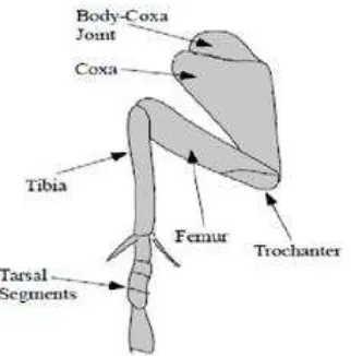
In order to design a leg structure of hexapod robot, cockroach used as a model for biological inspirations. Three segments, coxa, femur and tibia, divided the cockroach leg. The coxa-femur and femur-tibia were joints together and connected by soft tissue. This implies that each joint works much like a ball and socket joint, and it can contribute to the leg compliance for the purpose of shock absorbing.
Figure 2 : Cockroach leg structure
There have three-degree-of-freedom (3DOF) for front and middle leg and two-degree-of-freedom (2DOF) for rear leg. The leg structure translated, yawing, pitching and rolling motion in response to the input. Furthermore, the insect speed range was determined on a branch of periodic gaits.
6
opposing leg forces can be stable in the horizontal plane over a range of speeds. Each cockroach leg performs different function:
i. Front legs – used to push the body over the obstacles. It was important as a driver when turning and deceleration performed.
ii. Middle legs – acting as a support of the cockroach body and it also used to push the body over obstacles.
iii. Rear legs – act as a supporter of mass center and the contact point to prevent body from slipping down. It was generated the major part of the forward motion.
2.2 Biological Gait for Hexapod Robot
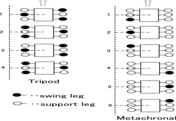
Cockroach legs have a symmetry arrangement which three legs arranged by row. The arrangement of cockroach leg was determined the stability in static position. By degree of freedoms, legs become a supporter device that maintains the stability when it starts moving.
The gait pattern of the cockroach was fixed on tripod gait, three legs are simultaneously swung. This walking pattern is popular in real insect world, and they can walk quickly by this pattern. The other gait is referring to the metachronal gait. metachronal gait was moving a leg gradually to move forward.
7
2.3 Hexapod Robot Actuator.
Actuator to automate mechanism of leg to walk or move should attach the hexapod robot. The actuator is a mechanical device that used for controlling and moving a mechanism system. An actuator typically a device generated by energy or power. The energy or power used to force an actuator usually created by air, electricity and liquid. The actuators usually used in mechanics mechanism are following below:
i. Pneumatic actuator ii. Electric actuator iii. Hydraulic cylinder
2.3.1 Pneumatic Actuator
A pneumatic actuator powered by air compressing system that convert it into motion. Pneumatic actuator generally include of a piston, a cylinder and valves. The piston was located in the cylinder that covered by a seal to keep the air in the upper part of cylinder and then allowed air pressure to force the seal downward. The pressure was moving the piston underneath and it is only have one spot for a signal input, top or bottom depending on action required.
Valve used for a signal to change the flow of compressed air in the system. Furthermore, it used to change the direction of piston whether extend or retracted. The motion of pneumatic actuator depends on type of actuator; it can be linear or rotary. Some types of pneumatic actuator were included:
i. Tie rod ii. Rotary iii. Grippers
8
2.3.2 Hydraulic Cylinder
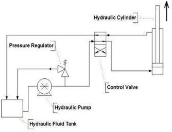
A hydraulic cylinder is a mechanical actuator was producing a motion by pressured of hydraulic fluid. It used to give a linear force due to a linear stroke. The hydraulic cylinder involved of a barrel, which have a piston connected to a piston rod. The barrel closed on each end by cap end and by head of cylinder. The hydraulic pressure acts on the piston to do linear work and motion.
The basic system of hydraulic included fluid reservoir, pump, control valve and hydraulic cylinder. Pump in hydraulic system used as a generator, which brings a flow of fluid to the system. The hydraulic actuator controlled by control valve to extend or retract. The force in the system use the Pascal law that similarly to F=PA whether F is equal to Force, P is pressure and A is define as area in hydraulic cylinder.
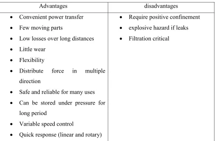
Table 1: Advantages and disadvantages of hydraulic system
Advantages disadvantages
Convenient power transfer Require positive confinement Few moving parts explosive hazard if leaks Low losses over long distances Filtration critical
Little wear Flexibility
Distribute force in multiple direction
Safe and reliable for many uses Can be stored under pressure for
long period
Variable speed control
9
10
2.3.3 Electric Actuator
Electric actuators are motorizing by electricity current. Generally, electric motor is a main device to create a mechanical motion converted from electricity. An electric motor was concern to the magnets and magnetism.
Then, it used magnets to create a motion by attraction of two poles of magnet bar and repelling force to moving rotational. There are two types of electric motor commonly used which is DC motor, AC motor and.
a) DC Motor
DC motor was drove by direct current power supply by using internal commutation, stationary permanent magnets, and rotating electrical magnets. DC motor maintenance involved regularly replacing the brushes and springs, which carry the electric current, and cleaning or replacing the commutator.
These components are necessary for transferring electrical power from outside the motor to the spinning wire windings of the rotor inside the motor.
Advantages of a DC motor include: i. Low initial cost
ii. High reliability
iii. Simple control of motor speed
Disadvantages of DC Motor include: i. High maintenance