i
INDUSTRIAL TEMPERATURE MONITORING SYSTEM
SIA JIA LING
This Report Is Submitted In Partial Fulfillment of Requirements For The Bachelor Degree of Electronic Engineering (Telecommunication Electronic)
Fakulti Kejuruteraan Elektronik dan Kejuruteraan Komputer Universiti Teknikal Malaysia Melaka
ii
UNIVERSTI TEKNIKAL MALAYSIA MELAKA
FAKULTI KEJURUTERAAN ELEKTRONIK DAN KEJURUTERAAN KOMPUTER
BORANG PENGESAHAN STATUS LAPORAN PROJEK SARJANA MUDA II
Tajuk Projek : INDUSTRIAL TEMPERATURE MONITORING SYSTEM
Sesi
Pengajian : 2-2012/2013
Saya ……….. (HURUF BESAR)
mengaku membenarkan Laporan Projek Sarjana Muda ini disimpan di Perpustakaan dengan syarat-syarat kegunaan seperti berikut:
1. Laporan adalah hakmilik Universiti Teknikal Malaysia Melaka.
2. Perpustakaan dibenarkan membuat salinan untuk tujuan pengajian sahaja.
3. Perpustakaan dibenarkan membuat salinan laporan ini sebagai bahan pertukaran antara institusi
pengajian tinggi.
4. Sila tandakan ( √ ) :
SULIT*
*(Mengandungi maklumat yang berdarjah keselamatan atau kepentingan Malaysia seperti yang termaktub di dalam AKTA RAHSIA RASMI 1972)
TERHAD** **(Mengandungi maklumat terhad yang telah ditentukan
oleh organisasi/badan di mana penyelidikan dijalankan)
TIDAK TERHAD
Disahkan oleh:
__________________________ ___________________________________ (TANDATANGAN PENULIS) (COP DAN TANDATANGAN
PENYELIA)
iii
DECLARATION
“I hereby declare that, except where otherwise indicated, this document is entirely my own work and has not been submitted in whole or in part to any other university.”
Signed : ……….. Author’s Name : SIA JIA LING
iv
APPROVAL
“I hereby declare that, I have been read this report and in my opinion it has been satisfied the scope and quality needed for Bachelor Electronic Engineering
(Telecommunication Electronics).”
Signed : ……….. Supervisor Name :
v
vi
ACKNOWLEDGEMENT
I would like to express my sincere appreciation to my family who always support me, encouraging me and offered comments to me to complete this whole project. Thank you for being patient to me and always give me the moral support all along.
I would like to express my sincere gratitude to my supervisor, Puan Yusmarnita Binti Yusop, for all her support and suggestion of this project, by giving me lots of encouragement and guidance. Your encouragement and knowledge helped me improve the project effectiveness.
vii
ABSTRACT
viii
ABSTRAK
ix
TABLE OF CONTENTS
CHAPTER TITLE PAGE
PROJECT TITLE i
DECLARTION iii
APPROVAL iv
DEDICATION v
ACKNOWLEDGEMENT vi
ABSTRACT vii
ABSTRAK viii
TABLE OF CONTENTS ix
LIST OF TABLES xii
LIST OF FIGURES xiii
LIST OF ABBREVIATIONS xv
I INTRODUCTION 1
1.1 Introduction of Project 1
1.2 Objectives of Project 2
1.3 Problem Statement 3
1.4 Scope of Project 3
1.5 Brief Explanation of Methodology 4
1.6 Report Structure 4
II LITERATURE REVIEW 6
x
2.2 Temperature Sensor 9
2.3 Signal Processing 12
2.4 MAX 232 13
2.5 Voltage Regulator LM7805 14
2.6 GSM Modem 14
2.7 AT Commands 15
2.8 Proteus 7 Professional 16
2.9 Programming Language 16
2.10 Visual Basic 17
2.11 Studies on the Existing Temperature Monitoring 18 System
III METHODOLOGY 20
3.1 Project Methodology 20
3.2 Factors that is taken into Considerations 22
3.3 Hardware Implementation 23
3.3.1 PIC16F877A Microcontroller 23
3.3.2 Sensor Module 25
3.3.3 Signal Conditioning Module 25
3.3.4 Crystal Oscillator 27
3.3.5 Voltage Regulator 28
3.4 Software Implementation 28
3.5 Hardware Construction 29
IV RESULTS AND DISCUSSIONS 31
4.1 Results on the First Stage 31
4.1.1 System Operating Flow 31
4.1.2 The Circuit Diagram 33
4.2 Results on the Second Stage 35
4.2.1 Designing the Hardware Circuit 36
xi
4.3 Results on the Third Stage 38
4.3.1 Testing 38
4.3.2 Analysis 39
4.3.3 Graphical User Interface Design 40
4.4 Discussion 42
4.4.1 Discussion on First Stage 42 4.4.2 Discussion on Second Stage 43 4.4.3 Discussion on Third Stage 45
4.5 Commercialization 47
4.5.1 Cost of the Prototype 47
4.5.2 Manufacturing Industry 48
4.5.3 Medical Industry 49
V CONCLUSIONS 50
5.1 Conclusion 50
5.2 Recommendation 51
REFERENCES 52
APPENDIX A 54
APPENDIX B 56
xii
LIST OF TABLES
NO TITLE PAGE
3.1 PIC16F877A Pin Connections 24
3.2 Digital Format that Transmitted to the Microcontroller 27 from the SO Output
4.1 The Actual Temperature and the Measured Temperature 34 With the % Error
xiii
LIST OF FIGURES
NO TITLE PAGE
1.1 The Basic Idea of Project Block Diagram 2
2.1 Basic Layout of Microcontroller 7
2.2 PIC 16F877A Pin Diagram 8
2.3 Operation of USART 9
2.4 Block Diagram of the System 12
2.5 Voltage Regulator LM7805 14
3.1 The Project Flow Chart 21
3.2 The K-Type Thermocouple Connections 25
3.3 Connection of MAX6675 and PIC16F877A 26
3.4 Crystal Oscillator Connection 27
3.5 Voltage Supply Circuit 28
3.6 PIC Programmer UIC00B 29
4.1 System Operating Flow Chart 32
4.2 The Circuit of the System via Simulation 33
4.3 Readings with Temperature Set at 24°C 34
4.4 The Actual Temperature versus Percentage Error Graph 35
4.5 PCB Layout through ARES 7 Professional 36
4.6 PCB of Hardware Circuit 37
4.7 Prototype of the Device 37
4.8 HyperTerminal Temperature Reading 38
xiv
4.12 Alert Message from System 41
4.13 Hardware Prototype 43
4.14 Full Connection of Device Prototype 44
4.15 UART Packet Form 44
4.16 Data Sampling Point by the UART 45
4.17 HyperTerminal Temperature Reading 45
xv
LIST OF ABBREVIATION
PIC - Programmable Interface Controller LCD - Liquid Crystal Display
GSM - Global System for Mobile LED - Light Emitted Diode PCB - Printed circuit board MCU - Microcontroller IC - Integrated circuit
ADC - Analog-to-Digital Converters DAC - Digital-to-Analog Converters
I/O - Input/Output
GUI - Graphic User Interface SMS - Short Message Service
1
CHAPTER I
INTRODUCTION
This chapter will discuss the introduction and the concept idea of the project. Besides that, the objectives of the project will also discussed and the problem statement will be explained clearly with the specified scope of the project. After that, the methodology of the project will also be described and the report structure will be presented in this chapter.
1.1 Introduction of Project
Temperature is the parameter that is important in daily lives [2] and industrial production [4]. Temperature acts as an important role in modern detection technique for production safety and energy conservation [2]. Temperature has been developing slowly due to the complexity of it. However, it had improved as man gained wider knowledge while trying to work with metals through the iron and bronze ages.
2
devices have been produced in order to provide for the needs from a range of sectors of the industries and applications.
Temperature is a very important element in manufacturing industry as it is used as the parameters to monitor the overall process and it will affect the quality of the product [2] if the temperature is out of specified range.
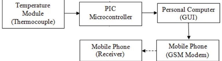
[image:17.595.151.535.387.493.2]The aim of this project is to implement an industrial temperature monitoring system by using GSM alert with the use of PIC 16F877A as the main processing unit and thermocouple as the sensor module. The temperature will present on the Visual Basic as the hyper terminal and it is interface with microcontroller through the use of USB to UART converter in order to monitor the temperature on personal computer. If the temperature is exceeding the specified range of temperature, a message will be sending out through the GSM modem to alert the user as showed in Figure 1.1.
Figure 1.1: The Basic Idea of Project Block Diagram
1.2 Objectives of Project
The main objective of this project is to develop an industrial temperature monitoring system. The following sub-objectives of this project were stated as to meet the main objective.
1. To enable user to adjust the range of the temperature anytime. 2. To develop the GUI in the personal computer by using Visual Basic.
3
1.3 Problem Statement
Nowadays, device with manually monitoring are inconvenient since it consumed more waiting time for human resource [3]. All the temperature parameters within the device have to be monitored manually if there is any error occurs. Besides that, it is very troublesome since it cannot be access anywhere and anytime if the temperature monitoring device is build-in within the monitoring system [3].
Besides that, the readings for most of the device with temperature monitoring system [5] are display through the use of LCD screen [4]. This is inefficient because the data shown on the LCD screen is very limited and it will be not convenient if there is any adjusting of the temperature.
In addition, the storage of the microcontroller for the historical data is very limited as it can only store up to 3 days with 5 seconds for each interval [4]. It is not efficient if the data for about a week ago is needed for the user for analysis of the product.
1.4 Scope of Project
There are several points that have been outlined in order to accomplish the objectives of the project. The scope of the project included:
1. Development of the Temperature Monitoring System that can be used to measure the temperature of the chamber based on PIC16F877A microcontroller.
2. Interfacing PIC microcontroller and personal computer using RS232 cable. 3. Interfacing the PIC microcontroller with the mobile phone by using another
mobile phone as the GSM modem for user to receive alert whenever the temperature is out of range.
4. Development of the Graphics User Interface by using Visual Basic in order to set the upper and lower temperature limit.
4
1.5 Brief Explanation of Methodology
This project is first started with the discussion with supervisor regarding the basic ideas of the project. After that, the scope and concept used also have been discussed. The background study and literature review of this project are done by referring to several sources such as I.E.E.E journals, conferences paper, reference book, data sheets and internet. After that, the components needed for this project such as microcontroller, temperature sensor and so on has also been searched in order to obtain more information on it. Then, suitable parts will be chosen to implement on this project. After that, the software required for this project is also studied and the most suitable programming language is used to program the codes for the system. In addition, the software used for simulation is also studied so that the simulation can be done successfully and can be proceed to the hardware part of the project. For the next stage, hardware is interfacing with the software and will progress to system testing. If there is any error occurs, the system required troubleshooting in order to achieve the desired result. Finally, the project is finalized and presented and can be proceed to thesis writing on the overall project.
1.6 Report Structure
This thesis discusses the design of the industrial temperature monitoring system. In general, it consists of five chapters.
Chapter 1 contains the general information of the project where it includes the introduction, objectives, problem statements, scope of work, methodology and the report structure of the project.
5
Chapter 3 introduces the methodology of the project which includes the flow chart of the overall system and the method used for implementation. This chapter also contained the software development for the project.
Chapter 4 documented the design and the result for the project outcome. the circuit diagram, program coding and the data collected are presented are discussed in this chapter.
6
CHAPTER II
LITERATURE REVIEW
This chapter reviews on the related projects so that the idea and the concept of the design can be obtained. Besides that, the related elements such as the microcontroller, temperature sensor, MAX6675 integrated circuit and some related software such as CCS C Compiler, Proteus 7 software and Visual Basic 6 are also discussed in this chapter.
2.1 Microcontroller
7
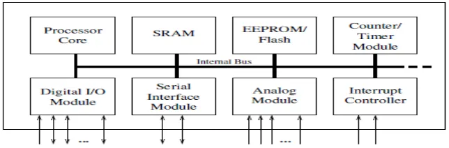
Figure 2.1: Basic Layout of Microcontroller
The processor core acts as the CPU of the microcontroller where it contains the control unit, registers and arithmetic logic unit. For the interrupt controller, it is very useful for interrupting the program flow in internal or external events and can help to conserve the power when it is in sleep modes [14]. Besides that, most of the microcontroller has two or three timer which it can be used to measure the intervals and so on. In addition, microcontroller contains at least one serial interface so that it can be used to download some program and communicate with the personal computer. Most of the microcontrollers offer various types of interfaces such as SPI since it can be used to communicate with external peripheral devices. Moreover, watchdog timer has been used so that crashes in microcontroller can be reset and it is very important to prevent errors occur in the program [14].
8
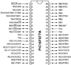
Figure 2.2: PIC 16F877A Pin Diagram
The number of pins for the input and output of the microcontroller is different based on the types of microcontroller used. It can be programmed to acts as either input or output to switch during the operations of the microcontroller. For the PIC16F877A, alternate function has been added for the I/O ports and will not be use as general purpose when the peripheral is enabled.
9
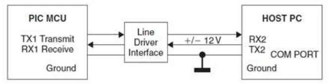
Figure 2.3: Operation of USART
2.2 Temperature Sensor
Based on the article of embedded temperature monitoring and control unit [1], it stated that by implement a temperature monitoring circuit, the working temperature can be monitored and control with the time set in the system. Every application required different types of temperature sensor and technology. There are three types of commonly used temperature sensor for the temperature measurement system.
Thermistors are a thermally variable resistor where the actual temperature can be estimated by the approximation between the resistance towards the electronics and the changing in temperature [1]. Positive temperature coefficient thermistors is type of a thermistors where the resistance increases as the temperature increase while the negative temperature coefficient thermistors is another type of thermistors where the temperature decrease as the resistance decrease. Thermistors are inexpensive, simplest and most sensitive temperature sensor used. However, it is easily broken and has a limited range where the temperature is not allowed to exceed 200°C. Hence, thermistors are more suitable for low cost and simple electronic circuit.