ZIGBEE-BASED SMART HOME SYSTEM
NURUL ILMI BINTI OMAR
This report is submitted in partial fulfillment of the requirement for the Bachelor Degree in Electronic Engineering (Wireless Communication) with Honors
Faculty of Electronic and Computer Engineering University Technical Malaysia Melaka
UNIVERSTI TEKNIKAL MALAYSIA MELAKA
FAKULTI KEJURUTERAAN ELEKTRONIK DAN KEJURUTERAAN KOMPUTER
BORANG PENGESAHAN STATUS LAPORAN PROJEK SARJANA MUDA II
Tajuk Projek : Sesi
Pengajian :
Saya NURUL ILMI BINTI OMAR mengaku membenarkan Laporan Projek Sarjana Muda ini disimpan di Perpustakaan dengan syarat-syarat kegunaan seperti berikut:
1. Laporan adalah hakmilik Universiti Teknikal Malaysia Melaka.
2. Perpustakaan dibenarkan membuat salinan untuk tujuan pengajian sahaja.
3. Perpustakaan dibenarkan membuat salinan laporan ini sebagai bahan pertukaran antara institusi pengajian tinggi.
4. Sila tandakan ( √ ) :
SULIT* *(Mengandungi maklumat yang berdarjah keselamatan atau kepentingan Malaysia seperti yang termaktub di dalam AKTA RAHSIA RASMI 1972)
TERHAD** **(Mengandungi maklumat terhad yang telah ditentukan oleh organisasi/badan di mana penyelidikan dijalankan)
TIDAK TERHAD
Disahkan oleh:
ZIGBEE-BASED SMART HOME SYSTEM
“I hereby declare that this report is the result of my own work except for quotes as cited in the references.”
“I hereby declare that I have read through this report entitled “ZigBee-Based Smart Home System” and found that it is enough in terms of scope and quality and has
complied the partial fulfillment for the awarding of the Bachelor of Electronics Engineering (Communication Wireless).”
Signature : ……….. Supervisor : ENGR. NOOR BADARIAH BTE ASAN
v
DEDICATION
vi
ACKNOWLEDGMENT
Alhamdulillah, praise to Allah S.W.T for the guidance and blessing upon me, for without it I would not have been able to come this far.
I wish to give my appreciation to my supervisors Engr. Noor Badariah bte Asan for their advice, understanding, good guidance and help throughout this project. Without their valuable suggestions and encouragement, this project would have not been successful.
vii
ABSTRACT
viii
ABSTRAK
ix
TABLE OF CONTENTS
CHAPTER CONTENT PAGE
PROJECT TITLE i
BORANG PENGESAHAN STATUS LAPORAN ii
REPORT ACKNOWLEDGEMENT FORM iii
STUDENT DECLARATION FORM iv
SUPERVISOR DECLARATION PAGE v
DEDICATION vi
ACKNOWLEDGMENT vii
ABSTRACK viii
TABLE OF CONTENT ix
LIST OF TABLE xii
LIST OF FIGURE xiii
LIST OF ABBREVIATIONS xv
1 INTRODUCTION
1.0 Overview 1
1.1 Project Background 1
1.2 Overview of Project 2
1.3 Problem Statement 2
1.4 Objective of Project 3
1.5 Scope of Project 3
x
1.7 Project Structure 7
2 LITERATURE REVIEW
2.0 Chapter Overview 9
2.1 Previous Project 10
2.2 Hardware and Theory 19
2.3 Software and Theory 24
3 PROJECT METHODOLOGY
3.0 Review of Project Methodology 27
3.1 Introduction 27
3.2 Process of Project 28
3.3 Preparation of Printed Circuit Boards 31
4 CONCLUSION
4.0 Introduction 36
4.1 Implementation 36
4.2 Simulation Result 38
4.3 Hardware Development 38
4.4 Software Development 40
xi
5 CONCLUSION AND RECOMMENDATION
5.0 Conclusion 50
5.1 Recommendation 51
REFERENCES 52
APPENDIX A 54
APPENDIX B 57
xii
LIST OF TABLE
TABLE TITLE PAGE
2.1 Wireless Standard 22
2.2 Long Range Data Integrity 23
2.3 Low Power of X-Bee 23
xiii
LIST OF FIGURE
FIGURE TITLE PAGE
1.1 Scope of Project 5
1.2 Block Diagram of Project 6
2.1 Block Diagram of Overall System 12
2.2 Block Diagram 13
2.3 Home Network Based on Zigbee 15
2.4 Zigbee Home Automation Architecture 16
2.5 System Composition Diagram 17
2.6 Architecture of Zigbee Network 18
2.7 Magnetic Sensor Circuit 20
2.8 Power Supply Circuit 20
2.9 Interface Circuit 21
2.10 X-Bee S2 24
2.11 Circuit Simulation Using Multisim 25
2.12 Layout of Proteus 26
3.1 Process of Project 29
3.2 Drilling Process 33
3.3 Soldering Process 34
3.4 Sucker Process 34
4.1 Block Diagram of Project 37
4.2 Simulation of Power Supply Circuit 38
4.3 Final Project 39
4.4 Hardware at The Residential Areas 39
xiv
4.6 PCB Layout of Power Supply 41
4.7 Setup COM Port 43
4.8 Coordinator Test 43
4.9 Setup Modem Configuration 44
4.10 Coordinator Set the DH and DL 45
4.11 Router Test 46
4.12 Router Terminal 47
xv
LIST OF ABBREVIATIONS
GSM - Global System for Mobile Communication PIC - Peripheral Interface Controller
LCD - Liquid-Crystal Display
SMS - Short Message Service
SPICE - Simulation Program with Integrated Circuit Emphasis
PCB - Printed Circuit Board
BASIC - Beginner's All-purpose Symbolic Instruction Code
RFID - Radio-Frequency Identification
LED - Light-Emitting Diode
GPRS - General Packet Radio Service
PC - Personal Computer
IEEE - Institute of Electrical and Electronic Engineers WSN - Wireless Sensor Network
WLAN - Wireless Local Area Network
Tx - Transmitter
Rx - Receiver
IC - Integrated Circuit
V - Voltage
1
CHAPTER 1
INTRODUCTION
1.0 Overview
This chapter will cover the introduction of the project where it involve of the project background, overview of the project, problem statement, objective of project, scope of project, thesis outline, and summary of work.
1.1 Project Background
2
1.2 Overview of Project
Security is considered a key issue when it comes to smart home system. The security system is one of the aspects to consider when building a home or residential areas. This is because the burglary case is more widespread and has taken seriously to ensure that this case can be reduced. The purpose of this security system is to ensure that homes and neighborhoods safe. Moreover, with this system the users can receive information more quickly in the event of unwanted items at home. We propose to design the project using microcontroller and magnetic sensors. Magnetic sensors are used to detect any vibration on the front door. The system has six blocks of magnetic sensors, the 555 timer circuits, the PIC 16F877A microcontroller, GSM and the ZigBee technology. The security system works when one of the houses in a residential area damaged by the robbers. Magnetic Sensors in the front door will detect vibration and send information to the sender via cable. The transmitter will send a signal to a receiver at the guardhouse by using ZigBee technology. The receiver will receive the signal and displays the number of homes that have been broken by the thief through the LCD display and an alarm will sound. In addition, the consumer or homeowner will receive SMS via GSM to tell that their home was broken into by thieves.
1.3 Problem Statement
3
1.4 Objective of Project
The aim of the project is to design and construct a control system which consists of smart security system that can be used for various purposesespecially teaching and learning and home application. The specific objectives of these projects are:
a) To design and develop smart security system using Zigbee technology. b) To help reduce burglary cases the area of housing.
c) To monitoring of smart home remotely and providing security when user is away from the home.
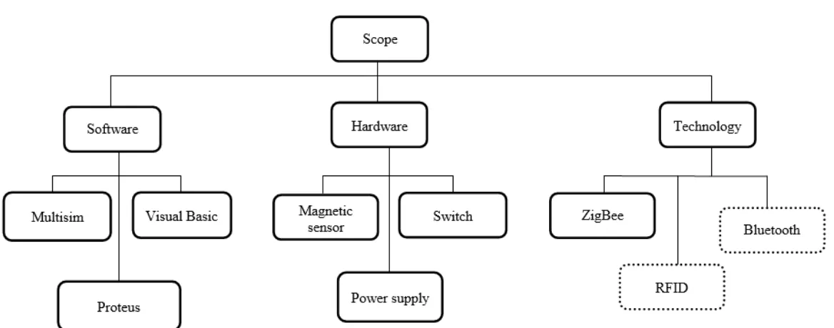
1.5 Scope of Project
The scope of project is shown in Figure 1.1.The scope of this project focused into three stages, which are hardware, software and technology development. In this project, it involves two parts in order to accomplish one complete system in wireless networking. It has two boards collectively from a Zigbee network, one of which is transmitter and receiver circuit. This project also uses the GSM (Global System for Mobile Communication) to enable the user or host information when they entered the home or residence of the robbers.
4 device, which may be mechanical, electromechanical, or piezoelectric. It is used to alert security guard who was in the hut to be aware that there is a housing area home was entered robbers.
5
6
1.6 Project Methodology
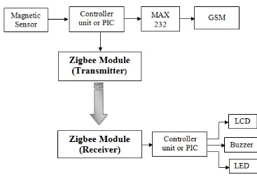
[image:21.612.147.514.234.497.2]The block diagram of project is shown in Figure 1.2. This project focuses on wireless transmission data and the project development based on Zigbee technology. The system has function properly when sensor active and microcontroller will send the data using Zigbee module to transmit and receive the data to the equipment. The project methodology shows that the step will be taken to complete the project.
Figure 1.2: Block Diagram of Project
The methodology of project regarding the project title is divided into two parts which is Hardware and Software. In Hardware part, this project will be design the security system for the home and need to understand how the system will be functioning.As far as hardware is concerned, open hardware designs will be created for various home automation components. These could then be assembled by users.
7 software for interfacing with devices, software for aggregating, analyzing, and acting upon these data.
1.7 Project Structure
This report is covered by five chapters. The first chapter starts with overview of project, objective, problem statement and scope of project. The literature review is discussed in Chapter 2 and project methodology in Chapter 3. The Chapter 4 covers hardware and software implementation and the conclusions and suggestions are respectively covers in Chapter 5. For projects that have been successfully implemented, there are some places to look into. Here are the main chapters:
Chapter 1: Study about objectives and scope of project.
The purpose of this project is to design and develop a ZigBee wireless system consisting of a sensor to detect if there is any effect of forced entry into the home.
Chapter 2: Literature review about wireless ZigBee system and sensor.
Research, find and read relevant topics from the sources such as reference books, internet and journal let’s get deeper knowledge and information for the project. Research on the system or even less in the market and know what are the characteristics and capabilities of the product will also provide more information and understanding in this project.
Chapter 3: Project methodology covers the planning, design and management of
development projects.
8
Chapter 4: Hardware and Software implementation.
The fourth chapter should focus on hardware and software development. In this chapter also shows the testing process. Testing will be performed on each module in both hardware and software systems.
Chapter 5: Conclusion and suggestion on the project.
9
CHAPTER 2
LITERATURE REVIEW