i
MATERIAL DETECTING AND HANDLING ROBOTIC ARM
NURULHUDA BINTI JALIL
This report is submitted in partial fulfillment of the requirements for the award of Bachelor of Electronic Engineering (Industrial Electronics) With Honours
Faculty of Electronic and Computer Engineering Universiti Teknikal Malaysia Melaka
ii
UNIVERS TI TEKNIKAL MALAYS IA MELAKA
FAKULTI KEJURUTERAAN ELEKTRONIK DAN KEJURUTERAAN KOM PUTER
BORANG PENGESAHAN STATUS LAPORAN PROJEK SARJANA MUDA II
Tajuk Pr ojek : MATERIAL DETECTING AND HANDLING ROBOTIC ARM
Sesi
Pengaji an : 2009
Saya NURULHUDA BINTI JALIL mengaku me mbenarkan Laporan Proje k Sarjana Muda ini disimpan di Pe rpustakaan dengan syarat-syarat kegunaan seperti berikut :
1. Laporan adalah hakmilik Un iversiti Teknika l Ma laysia Melaka .
2. Perpustakaan dibenarkan me mbuat salinan untuk tujuan pengajian sahaja.
3. Perpustakaan dibenarkan me mbuat salinan laporan ini sebagai bahan pertukaran antara institusi pengajian tinggi.
4. Sila tandakan ( √ ) :
SULIT*
(M engandungi maklumat yang berdarjah keselamatan atau kepentingan M alaysia seperti yang termaktub di dalam AKTA RAHSIA RASM I 1972)
TERHAD* (M engandungi maklumat terhad yang telah ditentukan oleh organisasi/badan di mana penyelidikan dijalankan)
TIDAK TERHAD
Disahkan oleh:
__________________________ ___________________________________
(T ANDATANGAN PENULIS) (COP DAN TANDATANGAN PENYELIA)
Alamat Tetap: POS 39, KG..PT.HJ.BAJURI, 83600 SEMERAH,
BATU PAHAT,JOHOR
iii
“I hereby declare that this report is the results of my own work except for quotes are cited in the references.”
Signature : ………
iv
“I hereby declare that I have read this report and in my opinion this report is sufficient in terms of the scope and quality for the award of Bachelor of Electronics Engineering
(Industrial Electronics) With Honours”
Signature : ……….. Supervisor’s Name : En. Mazran bin Esro
v
vi
ACKNOWLEGMENT
Alhamdulillah, praise to Allah S.W.T for the blessings bestowed upon me, with it I have come this far by completing this report for my Final Year Project.
I would like to take this opportunity to express my utmost and sincere gratitude to my supervisors, En Zamree bin Abd Ghani and En Mazran bin Esro. They have given me important advices, inspirations, and invaluable guidance throughout the whole project.
Secondly, I would also like to thank my beloved parents and family. They have given me the greatest moral support that I have ever had when I was feeling down. For this, my sincere love and acknowledgement goes especially for them.
On other hand, I would also like to show my appreciation to all the lecturers who taught me over the years in UTeM. Special thanks too to Mr Zulhairi bin Othman for his untiring effort on giving me ideas to complete this project. They have taught me invaluable knowledge which is essential in completing this project. I also would like to thank Automation Lab technician, En Shahrizan bin Johar for accompanying me during the course of this project.
vii
ABSTRACT
viii
ABSTRAK
ix
TABLE OF CONTENTS
CHAPTER CONTENT PAGE NUMBER
PROJECT TITLE DECLARATION ACKNOWLEGMENT ABSTRACT
ABSTRAK
TABLE OF CONTENTS LIST OF TABLES LIST OF FIGURES
LIST OF ABBREVATIONS
i ii iii iv vii viii x xi xii
I INTRODUCTION
1.1 Project Introduction 1.2 Project Background 1.3 Project Objectives 1.4 Problem Statement 1.5 Scope
1.6 Project methodology
x
II LITERATURE REVIEW
2.1 Introduction
2.2.1Robot Arm Constructions 2.2.2 Fishertechnik Kit
2.3 Programmable Logic Controller (PLC) 2.3.1 Basic Operation of PLC
2.3.2 Advantages of PLC 2.3.3 Programming the PLC
2.3.3.1 Ladder Logic
2.3.3.2 Software to program the PLC 2.3.3.3 OMRON Type CJ1 GH 2.4 DC Servo Motors
2.4.1 DC Servo Motor Speed Control 2.5 Sensing Units
2.5.1 Limit switch
2.5.2 Inductive proximity sensor 2.5.3 Capacitive proximity sensor
6 7 11 13 15 16 17 17 20 20 22 24 24 26 28 30
III METHODOLOGY
3.1 Introduction
3.2 Component selection 3.2.1 DC motor 3.2.2 Relay 3.2.3 Limit switch 3.2.4 Inductive sensor 3.2.5 Capacitive sensor
3.3 Project Implementation
3.2.1 Hardware Development and
xi
Implementation
3.2.2.1 Hardware calculation 3.2.3 Software Development and
Implementation 3.3 Flow Chart
3.4 Gannt Chart
36 38
43 46 47
IV RESULT AND DISCUSSION
4.1 Analysis
4.1.1 Hardware development 4.1.2 Software development 4.1.3 Integration
4.2 Result
4.3 Discussion 48 49 51 59 61 64
V CONCLUSION AND RECOMMENDATION
5.1 Conclusion
5.2 Recommendation
66
67
REFERENCES 68
APPENDIX A 69
APPENDIX B 77
xii
LIST OF TABLES
NO DESCRIPTION PAGE NUMBER
2.1 Five Robot Basic Motion. 8
2.2 2.3
Advantages, Disadvantages and Applications of Sensors. Rated operating distance correction factors.
26 28 3.1
3.2
D-Link parameter
Gannt Chart of project planning
35 44 4.1
4.2 4.3
Type of sensors i/p table
o/p table
xiii
LIST OF FIGURES
NO DESCRIPTION PAGE NUMBER
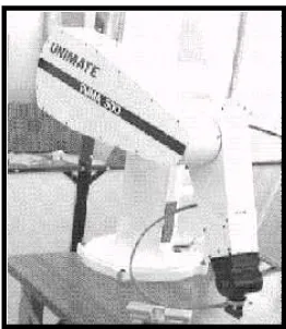
2.1 Unimation PUMA Robot Arm. 7
2.2 Cartesian x,y,z robot. 8
2.3 Cylindrical Robot. 9
2.4 Spherical Robot. 9
2.5 SCARA Robot. 10
2.6 Articulated or revolute robot. 10
2.7 Fishertechnik block diagram. 12
2.8 Example of Fishertechnik kit (industry robots). 13 2.9 A PLC unit with its range of applications. 14 2.10 A Basic Operation Block Diagram 15 2.11 A Simple Relay Layout and Schematic 18
2.12 A Simple Relay Controller. 18
2.13 A PLC Illustrated With Relays. 19 2.14 OMRON Training Kit with Handheld Console. 20
2.15 Six basic instructions PLC 21
2.16 DC Servo Motors. 22
2.17 Pulse Width Modulations for Servo Motors. 23
2.18 Types of Sensors. 25
2.19 Limit switch sensor. 27
xiv
2.22 Inductive proximity sensors. 29
2.23 Electronic output circuit and sensor electro- magnetic field 30
2.24 Capacitive sensor 30
2.25 Operation of capacitive proximity sensor 30
3.1 DC motor operating principle 32
3.2 DC motor 33
3.3 Relay OMRON MY2J 33
3.4 Limit switch 34
3.5 Inductive sensor 34
3.6 Capacitive sensor 35
3.7 Robot Arm Simulated in Robosim2 36
3.8 Simulation program at Robosom2 37
3.9 Flow chart step of calculation 38
3.10 Coordinate frames for the robotics arm 39 3.11 The convention in terms of joint axes 39 3.12 A Simple Ladder Diagram Simulated in Omron Type CJ1
GH Ladder Builder.
44
3.13 Flow chart of software programming 44 3.14 Integration between hardware and software. 45 3.15 Flowchart of the Project Development 46
4.1 Result from simulation 49
4.2 The part of fishertechnik kit 50
4.3 The whole robotic arm (b) The gripper will be build 50
4.4 Four respective boxes 50
4.5 The ladder diagram build and simulated in Omron Type CJ1 GH Ladder Builder.
58
4.6 Integration between hardware and software. 59
4.7 Relay OMRON MY 2J 59
xv
4.9 Wiring of capacitive sensor to PLC 60 4.10 The 8 Mechanical Relays used for this Project 61
4.11 Robot arm pick the material 61
4.12 Sensors detect the material 62
4.13 Robot arm stop at limit switch 62
4.14 Robot arm place the material 62
4.15 Robot arm back to origin 63
4.16 The whole robotic arm 63
xvi
LIST OF ABBREVIATIONS
DOF - Degrees of Freedom
PPP - Prismatic Prismatic Prismatic
SCARA - Selective Compliant Articulated Robot for Assembly RPP - Rovolute Prismatic Prismatic
CPU - Central Processing Unit
ECM - Electrically Commutated Motor FBD - Function Block Diagram IL - Instruction List
LD - Ladder diagram
1
CHAPTER I
INTRODUCTION
1.1 Project Introduction
The rapid growing and advancement of modern technology has yield to the developments and inventions of modern equipments and machineries. One of these inventions that give great impacts and implications to the lifestyles is industrial robotics arm. An industrial robot arm is meant to simplify task easier and still maintain its efficiency higher than that of a normal human operator in the industry [6]. These inventions have eased human significantly in all aspects and to upgrade of their daily lives. The basic robot arm consist of several rigid links connected in series by revolute or prismatic joints which can perform various task such as welding, material handling (pick & place), and thermal spraying, to painting and drilling.
2
This project is about the designing and development of ‘Material Detecting and Handling Robotic Arm’ which includes both hardware and software. The Robotic Arm shall be designed to pick and place materials from a conveyor to a box by detecting the type and color of the material. For this purpose, the sensors which are to detect the type and the color of the material will be place strategically at the conveyor and will the trigger the PLC to control the robotic arm. Robotic arm will then pick and place the material according to the range of movement by the DC motors which is limited by the use of limit switches. A gripper will be built according to the size of the material to pick and place it efficiently. From this project, the application of the sensors, motors and PLC can be shown in one package.
The objective of this project is to build, test and run the robotic arm as a working machine by using a PLC. This is because, this project will benefit students in future to understand the basics of PLC, DC motors, types of sensors and mechanical assembly once they step into the working environment.
1.2 Project Background
What is robotics? Robotics, computer-controlled machine that is programmed to move, manipulates objects, and accomplishes work while interacting with its environment. Robots are able to perform repetitive tasks more quickly, cheaply, and accurately than humans. The word robot has been used since to refer to a machine t hat performs work to assist people or work that humans find difficult or undesirable.
Here is the brief explanation of the robotics arm history. George Devol applied for the first robotics patents in 1954 (granted in 1961). The first company to produce a robot was Unimation, founded by George Devol and Joseph F. Engelberger in 1956, and was based on Devol's original patents. Unimation robots were also called programmable
transfer machines since their main use at first was to transfer objects from one point to
3
In 1969 Victor Scheinman at Stanford University invented the Stanford arm, an all-electric, 6-axis articulated robot designed to permit an arm solution. This allowed it to accurately follow arbitrary paths in space and widened the potential use of the robot to more sophisticated applications such as assembly and welding. Scheinman then designed a second arm and receiving a fellowship from Unimation to develop his designs, sold those designs to Unimation who further developed them with support from General Motors and later marketed it as the Programmable Universal Machine for Assembly (PUMA). In 1973 KUKA Robotics built its first robot, known as FAMULUS, this is the first articulated robot to have six electromechanically driven axes.
Interest in robotics swelled in the late 1970s and many US companies entered the field, including large firms like General Electric, and General Motors (which formed joint venture FANUC Robotics with FANUC LTD of Japan) [7].
1.3 Project Objectives
There are several objectives to be achieved in the end of the project which includes:
1. To develop a material detecting and handling robotic arm this can pick and place materials by detecting the type and color of the material.
2. To build, test and run the robotic arm as a working machine.
3. To study the types of sensors, motors and other components related in building this project.
4
1.4 Proble ms Statement
Industries nowadays are facing with the rising cost of labor and workforce because of the expanding global market that requires products to be delivered more and on time without affecting the quality of the product itself. Human operators in industries are more likely to cause mistakes and are not efficient compared to the use of machines. Machines are efficient and are considered cost saving on the long term. Besides that, the process cycle time is longer for human operators.
The robot arm is basically a machine that can replace a human operator and perform various tasks efficiently and still maintain a constant speed while handling the process. By the use of the robot arm too, cost for labor or workforce can be reduced significantly while still maintain a proper production of an industry.
This project highlights the problem in manufacturing industry. Since material has become in various type whether from metal or nonmetal material, packaging the material according to the color has made the respective industry to provide different packaging section or lines for avoid any mistakes.
The robot arm that is being developed in this project can be used in this industry without facing any problem since it can differentiate the type and color of the material, pick and place it according to the fix box. The process too shall be more efficient and faster than a normal human operator.
1.5 Project Scope
5
The hardware consists of mechanical structure and assembly; DC motors for movements, gripper for pick and place purposes, sensors as the sensing type and color of the material and a Programmable Logic Controller (PLC) to control the whole robot arm. The program will be developed in the CX-programmer and will be simulated before running on the project. Relays will be used to interface between the hardware (robotic arm) and the software (PLC program).
1.6 Project methodology
As stated at the objectives above, the robotic arm shall be build, test and run as a working machine, the process list below should be considered. The entire point list below is the process that has to be done from the start until the finishing part.
1. Literature review:
For this, a through research shall be done before starting on the project. Literature review will be done from research through books, journals and the internet in websites. This is to know the equipments, materials and components needed in building the project. Beside that, the research will include all the hardware that is related in this project such as the DC motors, sensors and other electrical/electronic components. Sensors too shall be studied and reviewed to find the perfect candidate for the job of detecting the type and color of the material.
2. Building the hardware:
6
3. Software development:
The software which is the PLC program shall be tested and simulated.
5. Finishing :
7
CHAPTER II
LITERATURE REVIEW
2.1 Introduction
This chapter will provide details and discuss about the source that are related to this project. It consists of the products that are already in the market nowadays and also contains the theory of the components, equipments, programming software and controller that will be used in the project.
8
2.2 Hardware development
2.2.1 Robot arm construction
An industrial robot is a general-purpose, computer-controlled manipulator consisting of several rigid links connected in series by revolute or prismatic joint. One end of the limb is attached to a supporting base while the other end is free and equipped with a tool or gripper to manipulate objects or to perform assembly tasks. The motion of the joints results in relative motion of the links.
Mechanically, a robot arm is composed of an arm and a wrist subassembly unit which is designed to reach work piece located within its work volume. The work volume is the sphere of influence that of a robot arm where its movements can deliver the wrist subassembly unit to any point within the sphere. The arm generally can move anywhere within the work volume by employing the correct Degrees of Freedom (D.O.F). The combination of the movements positions the wrist at the work piece. The wrist subassembly unit usually consists of three rotary motions.
[image:24.612.263.394.485.636.2]The concept is illustrated by the Cincinnati Milacron T3 robot arm and Unimation PUMA robot arm as shown on Figure 2.1.