EFFECT OF EXCESSIVE ELECTRICITY TO THE THERMAL CONDUCTIVITY OF AN AUTOMOTIVE ELECTRICAL SUPPLY
SYSTEMS
HAMIZAN AFANDI ROSADI B141110211
BMCT
Email: hamizanafandi534@gmail.com
Draft Final Report Projek Sarjana Muda II
Supervisor: ENGR MUHAMMAD ZULFATTAH BIN ZAKARIA
Faculty of Mechanical Engineering Universiti Teknikal Malaysia Melaka
DECLARATION
“I hereby declare that the work in this report is my own except for summaries and quotations which have been duly acknowledged.”
Signature : ………
Author :HAMIZAN AFANDI ROSADI
SUPERVISOR DECLARATION
“I hereby declare that I have read this report and in my opinion this report is sufficient in terms of scope and quality for the award of the degree of
Bachelor of Mechanical Engineering (Thermal-Fluid)”
Signature: ...
Supervisor: ...
ACKNOWLEDGEMENT
I would like to address my deepest gratitude to all those who had support me during the progress of this project. A special thanks to my Supervisor, Engr. Muhammad Zulfattah bin Zakaria for his guidance and contribution in giving in completing this report. Thanks to him also for giving exposure to the real technical life during conducting this project throughout the two semester.
ABSTRACT
This purpose of this study is to determine the effect of the output current and voltage from the automobile vehicle alternator to the temperature of the power cable that transmit the output current and voltage to the accumulator or the battery and to the other electrical components that need power to be functional. The alternator is an electrical generator that converts mechanical rotational energy into an alternating electrical current. The alternator uses the rotating magnetic field with a stationary armature. The alternator that used in automotive vehicles produces a direct current as the output power due to a current regulator is equipped inside the alternator to convert the alternating current output into direct current that can be stored inside the accumulator or battery for power supply.
In order to create a variation of engine speed and performance, a fuel consumption test scheme will be adapted as a benchmark. The test is going to run by using the dynamometer through dyno-testing machine in the laboratory. The parameter from each condition will be set and measured before the dyno-test is run. The dyno-testing session will ensure the performance of an automobile will not be influenced by any circumstances, such as road surface and wind blowing from surrounding. Dynamometer is a device that measures the output power and torque of an automobile engine without need the vehicle to travel along the roadside or the highway. The vehicle will be placed on the ‘rolling road’ and the wheels will rotate on the roller. The parameters according to the driving condition will be made up by using a heater to increase the ambient temperature or a cooling fan to reduce it otherwise.
The parameters are based on international standards of fuel consumption testing scheme that has been used worldwide to road cars and other automobiles. However, the test scheme will be selected according to the suitable climate in Malaysia to ensure the output current and voltage will be affected by the cable temperature and to ease the parameter set-up in the laboratory.
cable results by the cable temperature also affected the current flow inside the cable. The cable condition is also changes when it is used for a long time throughout the testing session. During testing session, several parameters need to be change and modified to suit the instruments limitation and by the advice by the technicians.
ABSTRAK
Tujuan kajian ini adalah untuk menentukan kesan arus dan voltan keluaran daripada alternator kenderaan automobil terhadap takat suhu kabel kuasa yang mengalirkan arus dan voltan ke akumulator untuk membolehkan komponen-komponen elektrik yang memerlukan kuasa berfungsi. Alternator adalah sebuah generator elektrik yang menukarkan kuasa putaran mekanikal kepada arus elektrik ulang-alik. Alternator ini menggunakan prinsip medan putaran elektrik dengan amatur statik untuk menghasilkan tenaga. Alternator yang digunakan dalam kenderaan automotif menghasilkan kuasa arus terus sebagai kuasa keluaran disebabkan oleh penstabil arus yang dipasangkan dalam alternator tersebut. Penstabil arus itu bertindak sebagai penukar pengeluaran arus ulang-alik kepada arus terus sebelum kuasa itu disimpan di akumulator atau bateri untuk bekalan tenaga.
Dalam mewujudkan keadaan yang mempunyai kepelbagaian kelajuan dan prestasi enjin, skim ujian penggunaan bahan api diadaptasi sebagai pengukuran kajian. Ujian ini akan dijalankan menggunakan dinamo meter melalui ujian dinamo di dalam makmal. Parameter setiap keadaan akan ditetapkan sebelum ujian dijalankan. Ujian dinamo ini akan memastikan prestasi sesebuah kenderaan tidak dipengaruhi oleh mana-mana halangan seperti keadaan permukaan jalan, dan tiupan angin dari persekitaran. Dinamo meter adalah suatu alat yang mengukur keluaran kuasa dan tujahan sesebuah kenderaan tanpa perlu memandu melalui jalan raya ataupun lebuh raya. Kenderaan yang bakal diuji akan diletakkan di atas ‘roda golek’ dan roda yang memacu akan bergolek di atas ‘roda golek’ tersebut. Parameter yang dikehendaki mengikut keadaan pemanduan akan ditetapkan menggunakan pemanas untuk meningkatkan suhu persekitaran ataupun kipas penyejuk untuk menurunkan suhu tersebut.
memberikan kesan kepada kabel kuasa serta memudahkan penentuan parameter di dalam makmal kelak.
Untuk sesi ujian dapatan kajian adalah berdasarkan kepada kenaikan suhu kabel kuasa apabila arus keluaran meningkat. Selain itu, rintangan daripada kabel kuasa juga memberikan kesan kepada pengaliran arus di dalam kabel. Keadaan kabel tersebut juga berubah apabila digunakan secara berterusan sepanjang ujian dijalankan. Semasa sesi ujian , beberapa parameter perlu diubah untuk menyesuaikan batas alatan serta nasihat dari juruteknik makmal untuk mengelakkan kerosakan alatan dan sebab-sebab keselamatan.
TABLE OF CONTENTS
CHAPTER CONTENTS PAGE
ABSTRACT i-iv
LIST OF TABLES AND FIGURES v
1 INTRODUCTION 1
1.0 OBJECTIVES 1
1.1 SCOPE 1
1.2 PROBLEM STATEMENT 2
2 LITERATURE REVEW 3
2.0 LITERATURE REVEW 3-4
3 METHODOLOGY 5
3.0 METHODOOLOGY 5-18
4 DATA AND RESULTS 19
4.1 TESTING SESSION 19-20
4.2 DATA COLLECTION 21-25
4.3 GRAPHICAL DATA 26-28
5 DISCUSSION AND ANALYSIS 29
6 CONCLUSION 33
6.0 CONCLUSION 33-34
6.1 RECOMMENDATION 34
REFERENCES 35-36
APPENDIX i-vi
FLOW CHART I
List of tables and figures
Table 1 extension cable constant parameter... 6
Table 2 fuel consumption test scheme parameters (Natural Resources Canada) ... 8
Table 3 fuel consumption test scheme parameters (VCA UK) ... 9
Table 4 Mastech MS2108A digital clamp meter specification ... 12
Table 5 Victor 86C Digital Multimeter specification ... 13
Table 6 properties of thermocouple type-K ... 14
Table 7 Proton Preve technical specification ... 15
Table 8 fuel consumption test scheme parameters (modified) ... 21
Table 9 output current for every testing scheme ... 22
Table 10 cable temperature on every testing scheme ... 23
Table 11 urban testing scheme cable resistance on cable temperature and output current .... 24
Table 12 air-conditioning testing scheme cable resistance on cable temperature and output current ... 24
Table 13 highway testing scheme cable resistance on cable temperature and output current 25 Table 14 advantages and disadvantages of cable insulation materials... 30
Figure 1 alternator wiring schematic diagram ... 5
Figure 2 engine and chassis dynamometer ... 11
Figure 3 Mastech MS2108A digital clamp meter and Victor 86C digital multimeter ... 13
Figure 4 thermocouple type-K probe wire ... 14
Figure 5 schematic diagram of instruments installation ... 16
Figure 6 the installation of extension cable from the power cable to the alternator output terminal ... 17
Figure 7 Test car is placed on the rolling road ... 17
Figure 8 the lab technician make the dyno calibration ... 17
Figure 9 the instrument setup to the extension cable ... 18
Figure 10 car fuse box ... 19
CHAPTER 1
INTRODUCTION
1.0 OBJECTIVES
The main objectives of this project is to obtain the temperature in the power cable caused due to the output current and voltage produced by the alternator in automotive electrical supply.
1.1 Scope
- This project is limited to these parameters:
1) The temperature of the cable and the output current and voltage from
the alternator will be measured by using thermocouple and multimeter that connected to a data logger.
2) Two similar automobile vehicle will be used as the test subject for
data verification
1.2 Problem statement
- In this project, there are several obstacles that need to be considered before
the data collection is running:
1) In reality, the power cable temperature is not uniform due to
inconsistent power required by the automobile vehicle and also the transient wind movement inside the engine compartment during idling and travelling.
2) The different driving condition is expected to affect the
CHAPTER 2
LITERATURE REVIEW
2.0 LITERATURE REVIEW
Most of the automobile electrical circuits are using 12 volts (V) of Direct Current (DC) system (Peters, 2000). In the automobile electrical system, the power generation component is the alternator (Julian & Oriti, 2001). The alternator is a dynamo or generator that generates an electric alternating current (Matsumoto, 2010). However, automobile electrical system is using direct current system. In order to overcome this, a current regulator is attached to the alternator output from alternating current to direct current. The power cable is used to transmit the electric current from the running alternator to the components of an automobile. Meanwhile, the alternator output current and voltage is depending on the speed of the running engine of the vehicle (Evans, Eng, Ph, & Eastham, 1983). When the engine is running at low speed, the alternator output current is low and the stored power in the accumulator will be used as backup. On the other hand, when the engine running in high speed, the output current and voltage higher, but, there are a regulator to maintain its output is not exceed the needs of the vehicle. This will ensure all the components inside the automobile is not damaged or broken due to overload power supplied (Lyon, Jr., Orlove, & Peters, 2000).
However, the conductivity of a power cable is limited by its maximum operating temperature (J. Tuttle, E. Canavan, 2014). If the cable is overstressed by the current load, the life cycle of the cable will be reduced. Besides that, power cables are designed to transmit a large value of electrical energy and the current
flow. The common power cable that is used is the stainless steel wire. Stainless steel wire is very strong and has a relatively high electrical and thermal resistivity. Furthermore, cables that conduct relatively high currents must have a low electrical resistance to avoid over-heating process, thus, damaging the cable (J. Tuttle, E. Canavan, 2014). The output current from the alternator is then being used for all the electrical components and to recharge the used accumulator or the battery of the automobile (Byrne, 1993).
In order to validate the data, the fuel consumption test scheme is used. The test is simulated in a laboratory by using the chassis dynamometer, which the vehicle is placed to run on the rolling road. This method will ensure the data collection is not affected by the surrounding circumstances, such as the weather and road condition. The parameters are going to be measured and setup according to the condition needed.
CHAPTER 3
METHODOLOGY
3.0 METHODOLOGY
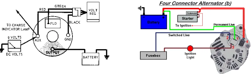
Firstly, there are two data to be measured which are current and temperature near the alternator. Thermocouple type-K probe that connected to the digital multimeter is attached to the cable and a digital clamp meter is clamped into the power cable.
Figure 1 alternator wiring schematic diagram
To validate the data, two identical automobiles in engine capacity and power is used as the test subject (Kelly, Mihalie, & Zolot, 2002). Then, the all three probes with the data logger will be attached to the alternator output cable that connected to the alternator output current and voltage to the battery or accumulator. The simulation of the driving condition is held on the dyno-testing machine. The testing is simulated at the same as the fuel consumption testing sessions. The automobile is measured under controlled conditions in a laboratory by using a standardized test procedure specified
by any authorized organization or federal law. There are 5 scheme of fuel testing that suitable for the Malaysia climates which are the urban cycle, extra urban cycle, highway cycle, air conditioning test cycle, and high speed or quick acceleration testing scheme.
In this experiment, the output current and temperature of the cable will results if there is any excess electricity flow outside the alternator or otherwise. If there is no current flow excessively inside the cable, the current may flows into different way such as heat to the cable or the alternator itself.
In the other hand, the heat that produced in the cable also affects to the cable resistance (Cooley, McConnell, & Hill, 1983).
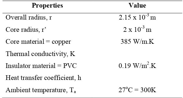
� = (� − ��)(4��′)√2ℎ��/�2 (1)
Where R is the cable resistance, T is the cable temperature, Ta is the ambient temperature, r’ is the core radius of the cable, r is the outside radius of the cable, h is
the surface of insulator heat transfer coefficient, K is the core thermal conductivity,
and I is the cable output cable flow value.
This experiment needed an extension cable that assembled from the end of the output cable in the wire harness to the output terminal of the alternator (Ahmad, 2011). This extension cable is used to ease the equipment placement as well as the data recording.
The properties of the cable is stated as constant throughout the testing session.
Table 1 extension cable constant parameter
From these properties values the analysis calculation can be simplified and the resistance of the cable can be obtained.
� = (� − ��)(0.025)(17.74)/�2 (2)
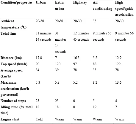
3.1Fuel Consumption Test (Natural Resources Canada)
The test is outline in Directive 93/116/EC as amended by Regulation (EC) 692/2008; that the test cycle is carried out in a laboratory at certain ambient temperature on a rolling road from a cold start (“5-cycle Testing _ Natural Resources Canada,” 2014). Furthermore, the extra-urban test cycle is carried out immediately following the urban testing is carried out. Highway cycle test meanwhile, is the combination simulation of both urban cycle and extra-urban cycle test.
All of these cycles consist of series accelerations, speeds, decelerations and idling. In air conditioning test, the vehicle’s climate control is used to lower the internal cabin temperature, thus, the load on the engine is increased. On the other hand, the high speed or quick acceleration begins warm, but the air conditioning system is not used.
Table 2 fuel consumption test scheme parameters (Natural Resources Canada)
The automobile tested have to be ‘run-in’ which means it must have been for at least 3000km before the test can be made.
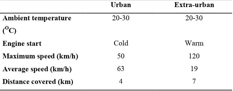
Extra-3.2Fuel Consumption Test (VCA United Kingdom)
VCA in an Executive Agency of the United Kingdom Department for Transport and the United Kingdom’s national authority for new road vehicle, agricultural tractors and off-road vehicles. The headquarters is placed in Bristol, with other offices worldwide in the US (Northville, Michigan and Ashland, Ohio), Asia-Pacific (Japan), Malaysia, China, India, Italy and Australia.
Official fuel consumption test procedures have been in use since the 1970s (“The fuel consumption testing scheme,” 2013). EU Directive 80/1268/EEC as amended or, for Euro 5 vehicles onwards, Regulation 692/2008 describe the tests which all new cars for sale after 1 January 2001 are required to take. There are two conditions for the test:
Table 3 fuel consumption test scheme parameters (VCA UK)
3.3 Dynamometer vehicle testing
Dynamometer in short term called “dyno” is a device that measuring the force, torque or power of a power producer parts such as an internal combustion engine. Dynamometer is commonly used in measuring the
performance of an automobile (S.S.Yegna Narayanan,
P.Ananthakrishnan, 1996). On the other hand, it is also used to determine the torque and power required to operate a driven machine such as a pump. In an automobile, there are two types of dyno that commonly used for performance measurement that are the engine dynamometer and chassis dynamometer.
1) Engine dynamometer – measures power and torque of an engine directly from the engine crankshaft or flywheel whenever the engine is removed from the vehicle. This type of dyno does not account the power losses in the drivetrain such as the gearbox and the wheels. 2) Chassis dynamometer – also called as the rolling road. This type of
dyno measures the power output from the wheel to the drive roller. The wheels of the vehicle will be placed on the rollers and the output is measured when the wheels turn.
3.4Cold-start condition
A cold start is an attempt to run the vehicle engine when it is still cold under its normal operating temperature (Comnac, Cernat, & Mailat, 2008). The cold start condition is commonly happening in a normal cold weather country where its climates are lower than the typical operating temperature of an engine. Cold starts are more difficult to run, thus, caused a vehicle is less efficient in fuel consumption and performance. These are due to several reasons:
1) The engine compression is higher as the lack of heat makes the ignition
process is difficult.
2) Low temperature caused the viscosity of the engine oil is higher, making
it more difficult to circulate.
3) The air becomes denser when in lower temperature. This affects the
air-fuel ratio, which affects the flammability of the mixture during ignition process.
3.5Experiment instruments
Due to the data logger is not available for the experiment session, a normal method was implemented to make the experiment is followed by the schedule. There were two types of instrument used during the experiment;
1) Digital clamp meter.
2) Digital multimeter
3) Thermocouple type-K multimeter.
4) Proton Preve test car.
Figure 2 engine and chassis dynamometer
These devices is provided by the supervisor which suggested to replace the usage of data logger during testing.
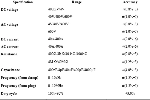
3.5.1 Digital clamp meter (Mastech MS2108A)
This device is used to measure the current flow inside the cable. This method will prevent the power cable from being damaged by cutting by knife. The specification of the digital
clamp meter is shown below (see Table 4)
Table 4 Mastech MS2108A digital clamp meter specification
Specification Range Accuracy
DC voltage 400mV/4V ±(0.8%+3)
40V/400V/600V ±(1.0%+5)
AC voltage 4V/40V/400V ±(0.8%+3)
600V ±(1.0%+5)
DC current 40A/400A ±(2.0%+6)
AC current 40A/400A ±(2.0%+6)
Resistance 400Ω/4k Ω/40 k Ω/400k Ω ±(0.8%+3)
4M Ω/40M Ω ±(1.2%+3)
Capacitance 400nF/4µF/40µF/400µF/4000µF ±(4.0%+5)
Frequency (from clamp) 0~10kHz ±(1.5%+5)
Frequency (from plug) 0~10MHz ±(1.5%+5)
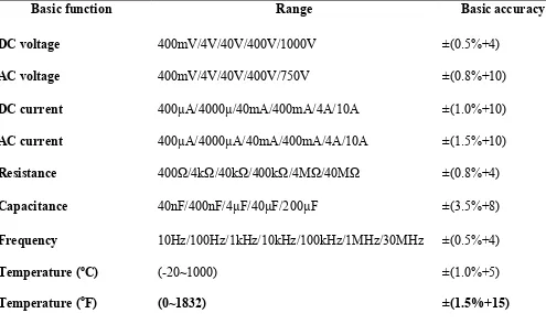
3.5.2 Digital multimeter (Victor 86C)
The digital multimeter is used to give the reading of the temperature of the power cable. Below is the specification of the device (see Table 5).
Table 5 Victor 86C Digital Multimeter specification
Basic function Range Basic accuracy
DC voltage 400mV/4V/40V/400V/1000V ±(0.5%+4)
AC voltage 400mV/4V/40V/400V/750V ±(0.8%+10)
DC current 400µA/4000µ/40mA/400mA/4A/10A ±(1.0%+10)
AC current 400µA/4000µA/40mA/400mA/4A/10A ±(1.5%+10)
Resistance 400Ω/4kΩ/40kΩ/400kΩ/4MΩ/40MΩ ±(0.8%+4)
Capacitance 40nF/400nF/4µF/40µF/200µF ±(3.5%+8)
Frequency 10Hz/100Hz/1kHz/10kHz/100kHz/1MHz/30MHz ±(0.5%+4)
Temperature (oC) (-20~1000) ±(1.0%+5)
Temperature (oF) (0~1832) ±(1.5%+15)
Figure 3 Mastech MS2108A digital clamp meter and Victor 86C digital multimeter