i
VISION BASED MAZE NAVIGATION USING NI-MYRIO
MUHAMMAD ZUL AZREN BIN SILAM
This Report Is Submitted In Partial Fulfillment of Requirements For The Bachelor Degree in Electronic Engineering (Computer Engineering)
Fakulti Kejuruteraan Elektronik dan Kejuruteraan Komputer Universiti Teknikal Malaysia Melaka
ii
UNIVERSTI TEKNIKAL MALAYSIA MELAKA
FAKULTI KEJURUTERAAN ELEKTRONIK DAN KEJURUTERAAN KOMPUTER
BORANG PENGESAHAN STATUS LAPORAN PROJEK SARJANA MUDA II
Tajuk Projek : VISION BASED MAZE NAVIGATION USING NI-MYRIO Sesi
Pengajian : 1 4 / 1 5
Saya MUHAMMAD ZUL AZREN BIN SILAM mengaku membenarkan Laporan Projek Sarjana Muda ini disimpan di Perpustakaan dengan syarat-syarat kegunaan seperti berikut: 1. Laporan adalah hakmilik Universiti Teknikal Malaysia Melaka.
2. Perpustakaan dibenarkan membuat salinan untuk tujuan pengajian sahaja.
3. Perpustakaan dibenarkan membuat salinan laporan ini sebagai bahan pertukaran antara institusi pengajian tinggi.
4. Sila tandakan ( √ ) :
SULIT* *(Mengandungi maklumat yang berdarjah keselamatan atau kepentingan Malaysia seperti yang termaktub di dalam AKTA RAHSIA RASMI 1972)
TERHAD** **(Mengandungi maklumat terhad yang telah ditentukan oleh organisasi/badan di mana penyelidikan dijalankan)
TIDAK TERHAD
Disahkan oleh:
__________________________ ___________________________________ (TANDATANGAN PENULIS) (COP DAN TANDATANGAN PENYELIA)
iii
“I hereby that this report is the result of my own work except for quotes as cited in the references.”
Signature : ………..
Author : MUHAMMAD ZUL AZREN BIN SILAM
iv
“I hereby declare that I have read this and in my opinion this report is sufficient in term of the scope and quality for the award of Bachelor of Electronics
Engineering.”
Signature : ………...
Author : DR. SOO YEW GUAN
v
ACKNOWLEDGEMENT
Praise to God that with His blessings I am able to finish this project in time successfully. I would like to express my greatest gratitude to my supervisor Dr. Soo Yew Guan for his guidance in finishing this project. My next deepest appreciation is dedicated to my parents and family for their money and moral support. Thanks to my friend who had helped me a lot in finishing this project. Last but not least to whom directly or indirectly contribute to this project.
vi
ABSTRACT
A vision based robot is a new technology that use image processing technique instead of using sensor. This to increase the various of application for the robot. Vision based robot mostly used for explore, for documentation, and so on. This project used Ni-myRIO from National Instruments as platform for the image processor. The existing type of this robot using robot that transfer the data and process by computer processor. The purpose of this project is to built a pocket-size image processing robot designed to be a navigation of a maze. The idea basically came from human. Human drive a car depends on a line to make sure the car in the middle of the lane and will turn according to the line. The methodology and scope of study are performed by doing literature reviews and research on various camera, motor, NI-myRIO, and the programming of the LabVIEW. Vision based Robot will have several criteria that are efficient, organized and user-friendly, which meets human needs.
vii
ABSTRAK
Robot berdasarkan penglihatan ini adalah antara teknologi baru yang
menggunakan teknik pemprosesan imej. Ini untuk mempelbagaikan applikasi. Robot berdasarkan penglihatan ini kebiasaannya digunakan untuk meneroka, dokumentasi, dan lain-lain. Projek ini menggunakan NI-myRIO sebagai dari National Instruments sebagai platform untuk pemprosesan imej.Robot sedia ada jenis berdasarkan
penglihatan ini menggunakan robot yang menghantar data ke komputer lalu diproses oleh pemproses komputer. Tujuan projek ini ialah untuk membina robot
pemprosesan imej poket saiz digunakan untuk navigasi di dalam maze. Idea ini datang dari manusia. Manusia memandu kereta berpandukan kepada garisan untuk memastikan kereta berada di tengah-tengah garisan dan akan membelok berdasarkan garisan. Metodologi dan skop kajian dilakukan dengan melakukan tinjauan
viii
TABLE OF CONTENTS
CHAPTER TITLE PAGE
PROJECT TITLE i
DECLARATION ii
ACKNOWLEDGEMENT v
ABSTRACT vi
TABLE OF CONTENTS viii
LIST OF TABLE xi
LIST OF FIGURES xii
I INTRODUCTION 1
1.1 Background of Project 1
1.2 Introduction of Project 1
1.3 Objective of Project 2
1.4 Problem Statement 3
ix
II LITERATURE REVIEW 5
2.1 Different Edge Detection Methodologies 5 2.1.1 First order edge detector 6 2.1.2 Second order edge detector 9 2.2 Vision Based System for Line Following Mobile
Robot 11
2.3 Image Based Segmentation Of Indoor Corridor
Floors For A Mobile Robot 13
2.4 Corridor Line Detection For Vision Based
Indoor Robot Navigation 16
III METHODOLOGY 20
3.1 General Process and Model Setup 21
3.2 Hardware 23
3.2.1 Webcam 23
3.2.2 NI-myRIO 23
3.2.3 DC Motor 25
3.3 Software 25
x
IV RESULT AND DISCUSSION 31
4.1 Raw image 31
4.2 Luminance image 34
4.3 Edge Detection 36
4.4 Threshold 38
4.5 Motor Connection 40
4.5.1 Straight movement 41
4.5.2 Reverse movement 42
4.5.3 Turn right movement 43
4.5.4 Turn left movement 45
4.6 Width Of The Maze 46
4.7 Pattern Matching 47
4.8 Discussion 49
V CONCLUSION AND RECOMMENDATION 51
5.1 Conclusion 51
5.2 Recommendation for Future Research 52
References 53
xi
LIST OF TABLES
NO TITLE PAGE
4.2 Option values for color format mode 35
4.3 Option for Method 38
xii
LIST OF FIGURES
NO TITLE PAGE
2.1.1.1 Equation of first order 6
2.1.1.2 Equation of vector 6
2.1.1.3 Equation of gradient vector 6
2.1.1.4 Robert cross-gradient equation 1 6
2.1.1.5 Robert cross-gradient equation 2 7
2.1.1.6 Robert cross-gradient equation 3 7
2.1.1.7 Robert cross-gradient equation 4 7
2.1.1.8 Robert cross-gradient equation 5 7
2.1.1.9 Robert cross-gradient equation 6 7
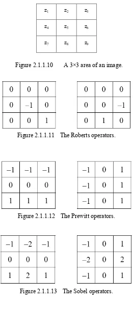
2.1.1.10 A 3×3 area of an image. 8
xiii
2.1.2.7 Dimension coordinate of Laplacian of Gaussian (LOG). 10
2.1.2.8 Differentation 11
2.2.1 Equation data 12
2.2.2 Sample of segmentation Image 12
2.3.1 Flowchart Of The Proposed Method For Floor Detection 13
2.3.2 Detection Algorithm Without Pruning 14
2.3.3 Detection Algorithm With Pruning 14
2.3.4 Gradient Magnitude Versus Intensity 15
2.3.5 Result Of Graph Based Segmentation 15
2.3.6 After Implement Proposed Method 16
2.4.1 Block Diagram Of The System 16
2.4.2 Original Intensity Image 17
xiv
3.3.1.1 Flow chart of decision making algorithm 28
3.3.1.2 Webcam view region 29
4.1.1 Coding part that grab the image 31
4.1.2 iMAQdc Open Camera block diagram 32
4.1.3 iMAQdc Configure Grab block diagram 33
4.1.4 iMAQdc Grab block diagram 33
4.1.5 Raw Image 34
4.2.1 Block diagram that convert the image into luminance 35 4.2.2 Connection of iMAQ Extract Color Planes 35 4.2.3 Different of raw image and luminance image 36
xv
4.3.2 iMAQ Edge Detection Block Diagram 37
4.3.3 Shows the output of the edge detection block 38
4.4.1 iMAQ Threshold block diagram 39
4.4.2 Shows output of Threshold block diagram 39 4.4.3 Different before and after Threshold block diagram 40 4.5.1 Connection of motor and motor driver. 40
4.6.1 iMAQ Clamp Horizontal Clamp block diagram 46
1
CHAPTER 1
INTRODUCTION
1.1 Background of Project
Vision-based navigation for mobile robot uses to navigate the mobile robot based on track line. The idea to develop this project is from people drive a vehicle. The line on the road is becoming their guide to follow during driving. On human body, they have their eyes to visualize the image of road line and analyze by human’s brain but robot uses camera to capture image of line and analyze by computer or embedded system.
The application of this project is in autonomous or unmanned robot. The robot will move based on vision-based navigation. The vision-based navigation or called by image processing will be done by the robot and will be the guide for the robot to move.
1.2 Introduction of Project
2
vital things that it needs to attain that the dependable, adaptable and quick reaction contrast and other versatile robot had been produced.
Vision-based navigation has been utilized as a part of unmanned or self-ruling vehicle. In this century, individuals began concentrate more points of interest to execute vision into independent vehicle. The focal points of this application are to stay away from the mischances and expand security by wiping out human misstep. In this extend, the fundamental objective is to create a portable robot which has capacity to explore focused around reference line or predefined way. Prior to this, there are numerous self-sufficient portable robots had created. Large portions of them utilized vision, infrared or ultrasonic sensors as their sensors to distinguish way. Each of sensors has its confinements and points of interest. On the off chance that we analyze among these sensors, the vision is superior to others focused around its adaptability. This is the fundamental component that numerous analysts changed infrared and ultrasonic sensors to vision sensor. Other than that, this task additionally presents the least difficult
algorithm and technique to process the data particularly for image processing.
When we have utilized a dream sensor as a part of portable robot so we have to process and break down the picture that we have captured. It called as image processing. Image processing is one of the essential courses of action for line emulating versatile robot that uses a dream. It will impact the execution of this task including response, flexible, reliable and so on. Because of that, simple technique and algorithm for image processing will produce faster response but it doesn’t determine either it more reliable or not. This project presents the simplest technique and algorithm but didn’t affect the reliable and flexible.
1.3 Objective of Project
3
2. To develop a robot for evaluating the proposed method
3. To build a stand-alone robot that can do image processing itself.
1.4 Problem Statement
In this century, there is a lot of navigation or line following mobile robots has been created. The issue is their mobile robots takes time in its decision so that it can’t move quick. In other word, we called as processing time. Processing time is measured from the information has identified until produce the output. One of the reasons it takes low reaction time is their algorithm or technique excessively perplexing where it needs a period to finish it despite the fact that its more dependable.
Besides, they had confronted issue that the development of their mobile robot still unpleasant. It is happened due to their algorithm or system didn't deliver a shut yield to match with state of track where precisely take after the track. For instance the track has bended to the left yet the versatile robot turned to left ahead of schedule than it ought to be or its point not suitable with the bend of track. So it will be out from the track.
Lastly, most of the mobile robot created using computer processing unit to do an image processing. That means, the robot not a stand-alone robot and need a device or components that connect the robot and computer processing unit. So when the robot is far or the computer have problem, the robot cant be functioning.
1.5 Scope of Project
4
sensor. The purpose using vision sensor as input is acts as a detector for reference line. In this project, the reference line is the edge detection.
5
CHAPTER 2
LITERATURE REVIEW
2.1 Different Edge Detection Methodologies
Edge detection is a basic tool used in image processing, basically for feature detection and extraction, which aim to identify points in a digital image where brightness of image changes sharply and find discontinuities. The purpose of edge detection is significantly reducing the amount of data in an image and preserves the structural properties for further image processing. In a grey level image the edge is a local feature that, with in a neighborhood separates regions in each of which the gray level is more or less uniform with in different values on the two sides of the edge. For a noisy image it is difficult to detect edges as both edge and noise contains high frequency contents which results in blurred and distorted result.
Edge detection makes use of differential operators to detect changes in the gradients of the grey levels. It is divided into two main categories:
6
2.1.1 First order edge detector
Figure 2.1.1.1 Equation of first order
An important quantity in edge detection is the magnitude of this vector, denoted ∇f, Where
Figure 2.1.1.2 Equation of vector
Another important quantity is the direction of the gradient vector. That is, 1
Figure 2.1.1.3 Equation of gradient vector
Computation of the gradient of an image is based on obtaining the partial derivatives of ∂f/∂x and ∂f/∂y at every pixel location. Let the 3×3 area shown in Fig. 2.1.1.1 represent the gray levels in a neighborhood of an image. One of the simplest ways to implement a first-order partial derivative at point z5 is to use the following Roberts cross-gradient operators:
Figure 2.1.1.4 Robert cross-gradient equation 1
7
Figure 2.1.1.5 Robert cross-gradient equation 2
These derivatives can be implemented for an entire image by using the masks shown in Fig. 2.1.1.2 with the procedure of convolution. Another approach using masks of size 3×3 shown in Fig. 2.1.1.3 which is given by
Figure 2.1.1.6 Robert cross-gradient equation 3 And
Figure 2.1.1.7 Robert cross-gradient equation 4
a slight variation of these two equations uses a weight of 2 in the center coefficient:
Figure 2.1.1.8 Robert cross-gradient equation 5
3 6 9 1 4 7
(
) (
)
y
G
z
z
z
z
z
z
Figure 2.1.1.9 Robert cross-gradient equation 6
A weight value of 2 is used to achieve some smoothing by giving more importance to the center point. Fig.2.1.1.4, called the Sobel operators, is used to implement these two equations.
8
z1 z2 z3
z4 z5 z6
z7 z8 z9
Figure 2.1.1.10 A 3×3 area of an image.
Figure 2.1.1.11 The Roberts operators.
Figure 2.1.1.12 The Prewitt operators.
9
2.1.2 Second order edge detector
The Laplacian of a 2-D function f (x, y) is a second-order derivative defined as
Figure 2.1.2.1 Second order derivative
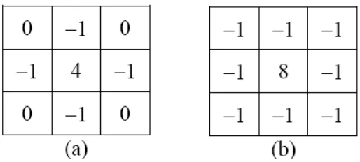
There are two digital approximations to the Laplacian for a 3×3 region:
Figure 2.1.2.2 Equation for 3 x 3 region 1st
Figure 2.1.2.3 Equation for 3 x 3 region 2nd
where the z’s are defined in Fig. 2.1. Masks for implementing these two equations are shown in Fig. 2.1.2.4