CONTINUOUS BATTERY MONITORING (CBM) SYSTEM FOR EARLY BATTERY FAILURE DETECTION
YUSOF BIN YUNUS
This Report Is Submitted In Partial Fulfillment Of Requirements For The Bachelor Degree of Electronic Engineering (Industrial Electronic)
Faculty of Electronic and Computer Engineering Universiti Teknikal Malaysia Melaka
ii
UNIVERSTI TEKNIKAL MALAYSIA MELAKA
FAKULTI KEJURUTERAAN ELEKTRONIK DAN KEJURUTERAAN KOMPUTER
BORANG PENGESAHAN STATUS LAPORAN
PROJEK SARJANA MUDA II
Tajuk Projek : Continuous Battery MonitoringFailure Detection (CBM) System for Early Battery
Sesi Pengajian : 1 3 / 1 4
Saya YUSOF BIN YUNUS
Mengaku membenarkan Laporan Projek Sarjana Muda ini disimpan di Perpustakaan dengan syarat-syarat kegunaan seperti berikut:
1. Laporan adalah hakmilik Universiti Teknikal Malaysia Melaka.
2. Perpustakaan dibenarkan membuat salinan untuk tujuan pengajian sahaja.
3. Perpustakaan dibenarkan membuat salinan laporan ini sebagai bahan pertukaran antara institusi pengajian tinggi.
4. Sila tandakan ( √ ) :
SULIT*
*(Mengandungi maklumat yang berdarjah keselamatan atau kepentingan Malaysia seperti yang termaktub di dalam AKTA RAHSIA RASMI 1972)
TERHAD** **(Mengandungi maklumat terhad yang telah ditentukan oleh organisasi/badan di mana penyelidikan dijalankan)
TIDAK TERHAD
Disahkan oleh:
__________________________ ___________________________________
(TANDATANGAN PENULIS) (COP DAN TANDATANGAN PENYELIA)
iii
“I hereby declare that this report is the result of my own work except for quotes as cited in the references”
iv
“I hereby declare that I have read this project report and in my own opinion this project report is sufficient in terms of the scope and quality for the award of Bachelor of
Electronic Engineering (Industrial Electronics) With Honors.”
v
ACKNOWLEDGEMENT
First and the most importantly, I would like to express the deepest appreciation to my project supervisor Engr Siti Aisyah Binti Anas for her supervision and advice
through this project. Without her guidance and persistent help this project would not have been possible.
Special thanks to my co. supervisor Engr Ranjit Singh Sarban Singh for
providing idea and motivation throughout the whole final year project. This project will not be possible to be completed without his help. I also would like to thanks to the PSM lab technicians, Mr Imran Bin Mohamed Ali for his help and advice during the whole Printed Circuit Board fabrication process.
vi
ABSTRACT
vii
ABSTRAK
viii
TABLE OF CONTENT
CONTENTS PAGE
CHAPTER 1 1.1 Introduction 1.2 Objective
1.3 Problem Statement 1.4 Scope of work
1 1 2 3 3 CHAPTER 2
2.1 Battery
2.1.1 Working of battery 2.2 Battery Maintenance 2.3 Types of Battery 2.4 Backup Battery
2.4.1 Selection criteria 2.4.2 Lifecycle cost 2.5 Battery management system
2.5.1 Voltage Monitoring 2.5.2 Discharge test 2.5.3 Conductance test 2.5.4 Ohmic testing
2.6 Effects of Charging on Battery Life 2.6.1 Sulfation
ix
2.6.2 Stratification 2.6.3 Gassing 2.7 Battery State of Health 2.8 Battery State of Charge
2.9 Battery System Failure Classification 2.9.1 Low capacity failure
2.9.2 Abrupt “power cut” failure 2.10 Battery degradation
19 19 20 21 21 22 22 23 CHAPTER 3
3.1 Introduction 3.2 Methodology
3.3 Concept of Continuous Battery Monitoring (CBM) for Early Battery Failure Detection
3.4 System Architecture
3.5 Real Time Clock (RTC) Circuit Design 3.6 Programming of PIC16F877A
24 24 25 25 26 35 38 CHAPTER 4
4.1 Overall flow 4.2 PCB Layout
4.3 Overview of the whole system 4.4 System operation
39 39 40 43 45 CHAPTER 5
5.1 Conclusion 5.2 Recommendation
x
LIST OF FIGURES
No TITLE PAGES
2.3.1 Types of Primary Batteries 7
2.3.2 Example of SMF Battery 9
2.3.3 Example of Lithium Battery 11
2.3.4 Nickel Cadmium (Nicd) Battery 12
3.3.1 Concept of Continuous Battery Monitoring (CBM) for Early Battery Failure Detection
26
3.4.1 Architecture Overview of Continuous Battery Monitoring (CBM) for Early Battery Failure Detection
27
3.4.2 Main flow part 1 32
xi
3.4.4 Main flow part 3 34
3.4.5 Main flow part 4 35
3.5.1 Real Time Clock (RTC) Design 35
3.5.2 Real Time Clock (RTC) Flow 37
4.2.1 PCB Layout Design for Real Time Clock Circuit 41
4.2.2 PCB Layout Design for Continuous Battery Monitoring Circuit
41
4.2.3 PCB Layout Design for Switching Circuit 42
4.2.4 PCB Layout design for Capacity Tester Circuit 42
4.3.1 Complete system from top view 43
4.3.2 Complete system from right side view 44
4.3.3 Complete system from left side view 44
4.4.1 Real Time Clock (RTC) 45
4.4.2 Checking battery 45
4.4.3 Indicate “battery good” 46
xii
4.4.5 Battery passes the capacity test 47
4.4.6 Short message send to user 48
4.4.7 Battery charging 48
4.4.8 Battery failed the capacity test 49
CHAPTER 1
INTRODUCTION
1.1Introduction
2
tooling, test equipment and work experience to become knowledge and effective in safe handling, operating and maintaining battery system. If the company cannot maintain the battery systems then one of the method is to oursource their battery maintenance to organizations that specialized, but by doing this method, it will involves high cost for maintenance. So,the company should specialized the maintenance battery system and then it will no need to for pay for another organizations that were specialized in battery maintenance system. But, some of these users believe that the investment into maintenance is worthless, since no matter how much labour is expended. This project aim to ensure that all application that using battery as their power to run smoothly at all the time, such as the elevator. The elevator using battery as it main backup power. During emergency or power loss, the power for elevator will switch to the batttery backup. If the backup battery is cannot operate or not sufficient to supply power for the elevator, it could be the big problem to the elevator system. This project will continously measuring the battery parameter to identify any factor that can cause battery failure. If the battery fail or damage or cannot peroform well, this device will inform to the user about the problem and the user need to replace the battery.
1.2Objective
3
1.3Problem Statement
Batteries are being installed in increasing numbers by cable and communications companies around the globe as an insurance policy against the riskc associated with disruptions or temporary loss of the commercial power grid. Proper preventive maintenance and monitoring of batteries is essential to optimize the considerable investment and assure the highest level of network quality of service. The conventional system only implementing a battery monitoring and maintenance program based on performing open circuit voltage combined with a long duration load testing is the highest quality state of health measurement technique. By using this technique, the technician must physically disconnect the battery string from service. discharge the batteries at a fixed rate and measure the time to reach the end voltage to determine the available capacity. After the test, the battery string must be reconnected and recharged before it is available for service. As a consequence, many operators do not implement a battery monitoring and maintenance program.
The main issue that actually become the idea to create this project is the system that using backup’s battery always fail because of battery failure. Other than that, battery need a manpower in order to ensure the performance of the battery by visit sites. In addition, it will consumes high cost to pay the service.
1.4Scope of Work
4
5
CHAPTER 2
LITERATURE REVIEW
2.1Battery
6
2.1.1 Working of Battery
A battery is a device, which consists of a various voltaic cells. Each voltaic cell consists of two half cells connected in series by a conductive electrolyte holding anions and cat ions. One half-cell includes electrolyte and the electrode to which anions move, i.e. the anode or negative electrode; the other half-cell includes electrolyte and the electrode to which cat ions move, i.e. the cathode or positive electrode.
In the redox reaction that powers the battery, reduction occurs to cations at the cathode, while oxidation occurs to anions at the anode. The electrodes do not touch one another but are electrically connected by the electrolyte. Mostly the half cells have different electrolytes. All things considered every half-cell is enclosed in a container and a separator that is porous to ions but not the bulk of the electrolytes prevent mixing.
Each half cell has an electromotive force (Emf), determined by its capacity to drive electric current from the interior to the exterior of the cell. The net emf of the cell is the difference between the emf of its half-cells. In this way, if the electrodes have emf and in other words, the net emf is the difference between the reduction potentials of the half-reactions.
2.2Battery Maintenance
7
fixed in the vehicle to avoid shake. Inverter battery should be placed on a wooden plank if possible.
2.3Types of battery
Each battery have their own characteristic. Batteries were design to suite several application.
a) Primary Batteries
[image:19.612.148.556.509.625.2]As the name indicates these batteries are meant for single usage. Once these batteries are used they cannot be recharged as the devices are not easily reversible and active materials may not return to their original forms. Battery manufacturers recommend against recharge of primary cells. Some of the examples for the disposable batteries are the normal AA, AAA batteries which we use in wall clocks, television remote etc. Other name for these batteries is disposable batteries. Figure 2.3.1 shows different types of Primary Batteries use around the world.
Figure 2.3.1 Types of Primary Batteries
8
Secondary batteries are also called as rechargeable batteries. These batteries can be used and recharges simultaneously. They are usually assembled with active materials with active in the discharged state. Rechargeable batteries are recharged by applying electric current, which reverses the chemical reactions that occur during discharge. Chargers are devices which supply the required current.
Some examples for these rechargeable batteries are the batteries used in mobile phones, MP3 players etc. Devices such as hearing aids and wristwatches use miniature cells and in places such as telephone exchanges or computer data centre’s, larger batteries are used. There are several types of secondary battery :
i. Sealed Maintenance Free (SMF)Battery
SMF is a sealed maintenance free battery, designed to offer reliable, consistent and low maintenance power for UPS applications. These batteries can be subject to deep cycle applications and minimum maintenance in rural and power deficit areas. These batteries are available from 12V.
9
Figure 2.3.2 Example of SMF Battery
ii. Lead Acid Battery
Lead Acid batteries are widely used in automobiles, inverters, backup power systems etc. Unlike tubular and maintenance free batteries, Lead Acid batteries require proper care and maintenance to prolong its life. The Lead Acid battery consists of a series of plates kept immersed in sulphuric acid solution. The plates have grids on which the active material is attached. The plates are divided into positive and negative plates. The positive plates hold pure lead as the active material while lead oxide is attached on the negative plates.
10
This results in the release of electrons from the positive plates which will be accepted by the negative plates. This leads to the formation of an electric potential across the battery. The electrolyte in the Lead Acid battery is a mixture of Sulphuric acid and water which has a specific gravity. Specific gravity is the weight of the acid-water mixture compared to equal volume of water. The specific gravity of pure ions free water is 1[3].
The lead-acid batteries provide the best value for power and energy per kilowatt-hour; have the longest life cycle and a large environmental advantage in that they are recycled at an extraordinarily high rate. No other chemistry can touch the infrastructure that exists for collecting, transporting and recycling lead-acid batteries.
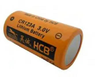
iii. Lithium (Li) Battery
11
Figure 2.3.3 Example of Lithium Battery
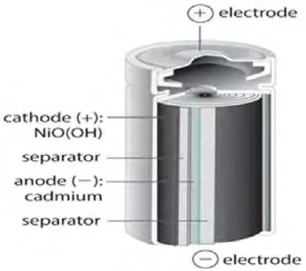
iv. Nickel Cadmium (Nicd) Battery
12
Figure 2.3.4 Nickel Cadmium (Nicd) Battery
2.4Backup battery
Backup power can also be called as stationary battery. It is the single most reliable power supply at a power generating station. It remains on float charge, waiting until it is called upon to serve in emergency capacity for which it was designed. In order to meet this requirement, proper care is essential. Start from the installation and continuing throughout its life.[4]
2.4.1 Selection Criteria