FAKULTI KEJURUTERAAN ELEKTRIK
ANALYSIS OF THREE PHASE INVERTER OF BLDC
MOTOR
AIN AFIFAH BINTI AHIARUDDIN
DEGREE OF ELECTRICAL ENGINEERING (POWER ELECTRONIC AND DRIVES)
ANALYSIS OF THREE PHASE INVERTER FOR BRUSHLESS DC(BLDC) MOTOR
AIN AFIFAH BINTI AHIARUDDIN
This Report Is Submitted In Partial Fulfillment of Requirements for the Degree in Electrical Engineering (Power Electronic and Drive)
Faculty of Electrical Engineering
UNIVERSITI TEKNIKAL MALAYSIA MELAKA
DECLARATION
I declare that this thesis entitled “Analysis of Three Phase Inverter for Brushless DC(BLDC) Motor” is the result of my own research except as cited in the references. The thesis has not been accepted for any degree and is not concurrently submitted in candidature of any other degree.
Signature :
Name : AIN AFIFAH BINTI AHIARUDDIN
APPROVAL
I hereby declare that I have read this report and in my opinion this report is sufficient in terms of scope and quality as a partial fulfillment of Degree of Electrical Engineering (Power Electronic and Drives)
Signature :
Supervisor Name : PUAN NORHAZILINA BT BAHARI
DEDICATION
i
ABSTRACT
ABSTRAK
ACKNOWLEDGEMENT
First of all, I would like to give my thankfulness to almighty Allah S.W.T. for given me strength to finish my Final year project, BEKU 4792 in the given time. All the things we do are under his control and without his permission nothing can be done successful.
Also, not forgotten, my parents that always pray for my successful and give support to everything good that I do. My supervisor, Madam Norhazilina Bt Bahari that have given me help and much advice for the project, also to all lecturer that have helped me in many ways a lot. My thankfulness also goes to all my friends that help me a lot through the flow of my project in this 2 semester and all people that have help me in any way. All kinds of helps and support from all person I really appreciate and will not be forgotten as I am still alive.
v
2.2.2 Basic Principle of BLDC motor 11
2.3 INVERTER 15
2.3.1 Current Source Inverter (CSI) 16
2.3.2 Voltage Source Inverter (VSI) 17
2.3.4 Comparison of CSI and VSI 18
2.3.5 Hysteresis PWM Current Control 19
3.5 Description of the BLDC Motor Drive System 31
3.6 Modeling of BLDC Motor 35
4 RESULT AND DISCUSSION 39
5 CONCLUSION
5.1 Conclusion 49
5.2 Recommendation/ Future work 49
LIST OF TABLES
NO TITLE PAGE
2.1 Switching sequence Table 14
2.2 The comparison of current source inverter and voltage source inverter. 18
3.1 Gantt chart (Project Progress for semester 1) 28
3.2 Gantt chart (Project Progress for semester 2) 29
4.1 Comparing table for selecting Kp value 47
4.2 PI controller parameter characteristic 48
LIST OF FIGURES
NO TITLE PAGE
2.1 Cross section of a two pole dc motor 8
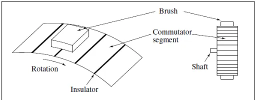
2.2 brush and commutator segment of dc motor 8
2.3 Typical brushless dc motor control system 11
2.4 Typical three phase current waveform in the BLDC motor 12
2.5 Ideal back-emf’s, phase currents and position sensor signals 13
2.6 BLDC motor cross section and phase energizing sequence 13
2.7 Schematic for Inverter System 16
2.8 Schematic for CSI Inverter System 16
2.9 Schematic for VSI Inverter System 17
2.10 Hysterisis PWM, current control and switching logic 19
2.11 Hysterisis current control modulation scheme 20
2.13 Hysterisis current controller at Phase “a” 21
2.14 Three phase inverter for hysterisis current control 22
3.1 Flowchart of planning progress of project 27
3.2 Basic Block Diagram of BLDC MOTOR Drive System 30
3.3 Proportional integral (PI) controller blockset 32
3.4 The blockset of Hysteresis Current Controller 33
3.5 Equivalent circuit of a BLDC motor connected to an 35
4.1 Rotor speed,wm (rad/s) versus Time,t (sec) 39
4.2 Current Reference, Iref_abc(A) versus Time,t (sec) 40
4.3 Current Reference, Iref_a(A) versus Time,t (sec) 41
4.5 Current Error,Ierror_a(A) versus Time,t (sec) 42
4.6 Electromagnetic Torque,Te(Nm) versus Time,t (sec) 42
4.7 Current waveform for Ha,Hb and Hc with respect to rotor electrical angle 43
4.8 Stator Back-EMF,Eabc (V) versus Time,t (sec) 44
4.9 Graph of speed response with parameter Kp = 0.1, Ki = 10 45
4.10 Graph of speed response with parameter Kp = 0.2, Ki = 5 45
4.11 Graph of speed response with parameter Kp = 1, Ki = 15 46
4.12 Graph of speed response with parameter Kp = 2, Ki = 15 46
LIST OF SYMBOLS
BLDC - Brushless Direct Current Motor
AC - Alternating Current
Back-emf - Back Electromagnetic Force
PWM - Pulse Width Modulation
VSI - Voltage Source Inverter
CSI - Current Source Inverter
EMI - Electromagnetic
PID - Proportional Integral Derivative
Kp - Proportional gain
1
CHAPTER 1
INTRODUCTION
1.1 PROJECT BACKGROUND
Due to the their efficiency, silent operation, realibility and compact form, BLDC motor have been desired for small horsepower control motors. Nowadays, household appliance is one of fastest-growing end-product market for electronic motor drive.
Actually, BLDC motor is one type of permanent magnet synchronous motor that can be driven by dc voltage but current commutation is done by solid state switches. The commutation instant are determined by the rotor position that will detected by position sensor or by sensorless technique [1]. These position sensors may be a hall sensors, resolvers or absolute position sensor. The most type of sensor that normally use is hall sensor and optical encoders. These sensor especially hall sensors are temperature sensitive and limit.
This simulation will be model by using MATLAB Simulink Software. Simulation is the most important to evaluate, design and make an analysis of power electronic inverter that apply such as at BLDC motor. The benefit by using MATLAB software because it provides immediate access to thousand of fundamental and can be built-in graphing tools and GUI builder to ensure that can customize data and model to help interpret data more easily for quicker decision making.
3
1.2 PROJECT MOTIVATION
A brushless DC motor (BLDC) is the most popular of applications for home appliance and industries such as for medical, aerospace and also can be used in outdoor fan in air-conditioner. It is because their advantage that high efficiency, lower weight, reliability and also low cost. To control of BLDC motor, an electronic commutation is applied and will make Power Electronic circuit more complexity. Basically, Voltage Source Inverter (VSI) can be used to achieve accurate and better performance of BLDC motor. Normally, in designing motor drive, the suitable designing is by using modeling and simulation compared to building prototypes because of the cost.
1.3 PROBLEM STATEMENT
In many cases, the brushless DC (BLDC) motor can replace conventional DC motor. BLDC motor are very suitable for air conditioning system application because of their small size, high reliability, high efficiency and very excellent speed torque characteristics. Induction machines more difficult to control and achieved torque speed range compare to the BLDC motor. In term of efficiency, BLDC motor can operate at unity power factor but for induction machines the best power factor only around 85 percent.
5
1.4 OBJECTIVES
The main objective in this project is to design and make an analysis of BLDC motor by using MATLAB Simulink Software. In order to achieve the goal of this project and solve the current problem, an objective of this project is determined:
1) To analyzed the performance of BLDC motor drive.
1.6 REPORT OUTLINES
Chapter 1 will fullfill the introduction of three phase inverter for BLDC motor. The overview of project objectives, problem statement for this project analysis, scope of work and methadology project which is the method that uses in order to finish this project.
Chapter 2 focuses on the literature review such as theorytical, basic principles and basic topologies that relates to this project. The research that running is about BLDC motor, inverter and air conditioner.
Chapter 3 discusses about methadology of this project. The gantt chart and flowchart also included in this chapter. This chapter also will discuss about circuit design and the system work. Other than that, in this chapter will discuss about related previous work and will make a comparison about this.
Chapter 4 will explain the results obtain during construction circuit in Matlab Simulation. Among the result that will be discussed about output waveform which is sinusoidal and trapeizoidal waveform that will produce in different input voltage.
7
CHAPTER 2
LITERATURE REVIEW
2.1 INTRODUCTION OF DC MOTOR
In daily life, an electric equipment that we use often to have at least one motor used to rotate an object from its position. In the market have many type of motor such as induction motor, servomotors, DC motor (brushed and brushless). To choose the suitable type of motor depends on the application requirement [3].
2.1.1 Construction
Figure 2.1: Cross section of a two pole dc motor
As the rotor states, the brushes move from one segment to another which commutates the current in such a way that the currents in the conductor under each pole flow in the same direction which is from stator point of view have been depicted in Figure 2.2. The resulting force vectors that act on the rotor windings are all tangetial to the rotor periphery and contribute to the torque.
9
2.2 BRUSHLESS DC (BLDC) MOTOR
2.2.1 Introduction
Brushless DC motors also can be known as electronically commutated motors that are powered by direct-current (DC) electricity and having electronic commutation systems rather than mechanical commutator and brushes [5]. BLDC motor having permanent magnets on the rotor and trapeizoidal shape back-EMF. BLDC motor also one kind of permanent magnet synchrous motor. The Brushless Direct Current (BLDC) motor used in a medical application, industries and also used in aerospace and defense application for recent years. It very ideal for application that require high reliability, high efficiency and high performance motor because it capable to providing large amount of torque over a vast speed range.
The application that suitable for BLDC motor such single-speed applications, adjustable speed, position control, and in low-noise application. In term of single speed, BLDC are good for this application because of the flat speed torque curve when speed has to be maintained in the variation of load. To monitor torque, speed and position control for BLDC motors a complex controllers and optical encoder can use for it. The BLDC motors also generate EMI and noise but its better compare to Brushed DC motor [2].