CAR SECURITY ALERT SYSTEM
MOHAMAD FIRDAUS BIN MOHAMAD RAMDZAN
This Report Is Submitted In Partial Fulfillment Of Requirements For The Bachelor Degree of Electronic Engineering (Telecommunication)
Fakulti Kejuruteraan Elektronik Dan Kejuruteraan Komputer Universiti Teknikal Malaysia Melaka
ABSTRACT
Keyword
1. Arduino Uno 2. HC SR04
3. Proteus Design Suite 4. Range Finder
CAR SECURITY ALERT SYSTEM
MOHAMAD FIRDAUS BIN MOHAMAD RAMDZAN
This Report Is Submitted In Partial Fulfillment Of Requirements For The Bachelor Degree of Electronic Engineering (Telecommunication)
Fakulti Kejuruteraan Elektronik Dan Kejuruteraan Komputer Universiti Teknikal Malaysia Melaka
Specially dedicated to my beloved parent:
Mohamad Ramdzan Bin Pelet
Haslina Bte Ab.Rahman
To my Supervisor:
Mdm. Siti Rosmaniza Bte Ab Rashid
Also to all my fellow friends who have encouraged
and inspired me. Thanks for all the support and
VI
ACKNOWLEDGEMENT
In the name of Allah, the Most Gracious and the Most Merciful
ABSTRACT
VIII
ABSTRAK
List of Table
List of Table Page
Table 1.1 General Road Accident data in Malaysia 2
Table 2.1 Comparison of Arduino 12
Table 2.2 Product Specification and Limitation 13 Table 2.3 Comparison of Range sensor in market 15
Table 2.4 Pin Description of 74HC595N 18
Table 3.1 List of Component 27
X
List of Figure
List of Figure Page
Figure 1.1 Arduino Library 4
Figure 2.1 Communication between Car 8
Figure 2.2 16x2 LCD display 9
Figure 2.3 Arduino Structure 10
Figure 2.4 Arduino Uno R3 12
Figure 2.5 Cycle of wave 14
Figure 2.6 Layout of HC SR04 14
Figure 2.7 Connection of Ultrasonic Sensor 15
Figure 2.8 Buzzer 16
Figure 2.14 Interface of Arduino Software 22
Figure 3.1 Project Flowchart 25
Figure 3.2 Project Implementation 26
Figure 3.3 Etching Process Flowcharts 28
Figure 3.4 Circuits on ARES 29
Figure 3.5 Circuits on ISIS 30
Figure 3.6 Personal Protection Equipment 31
Figure 3.7 Printed Circuit 31
Figure 3.8 Positive PCB Board 32
Figure 3.10 PCB in UV machine 33
Figure 4.8 Arduino Structure 46
XII
2.2.1 Distance Measuring (Hurdle Detection System) for 7 Safe Environment in Vehicle through Ultrasonic
2.2.2 Car Anti-Collision and Intercommunication System 7 Using Communication Protocol
2.2.3 Ultrasonic anti crashing system for automobiles 8
2.3 Hardware 9
2.3.1 Liquid Crystal Display 9
2.3.2 Arduino 10
2.3.3 Ultrasonic Sensor 12
2.3.4 Buzzer 16
3.4 Project Implementation 26
3.4.1 Circuit Development 27
4.2.1 Hardware and Prototype 42
XIV
Chapter V
5.1 Introduction 55
5.2 Conclusion 56
Chapter I
Introduction
2
Project Background
Nowadays, all products in the market have their own disadvantage or weakness. The designed product start with the basic thing before the creator adds some element as the enhancement from the current product. All this matter is to follow the flow of technology improvement that expanded every day. Therefore, this project has the same purpose, but with enhancements to give an advantage to the user or consumers. Problems that occur from an existing product will be improved and the problem is identified from a few factors like functionality, reliability, and security.
Driving is a routine activity for most people and they use their car to move from one place to another place. Numbers of vehicle were increasing day by day and make a risk of accident increase. The numbers of accident are so high and it occurs every time and anywhere and leads to a worst damage, serious injury and probably causing death. Based on the table above, the statistic show from 1995 until 2012 had increasing of road accident due to increasing of vehicles. [7]
This Car Security Alert System is design to develop a new system that can notify driver if the car reaches the dangerous distance. Using ultrasonic as a ranging sensor, its function based on ultrasonic wave. After transmit by transmitter, the wave is reflected back when obstacle detected and receive by receiver. The main target for this project is notification from buzzer and LED give an alert to driver when the car reach distance less than the predetermined distance set in the system, whileLCD will display the status of distance and range or distance of car with the next car
1.1 Objective
The main objective of this project is to design an alert system that function to alert the driver if car reach certain distance that declared as dangerous distance.
1.2 Problem Statement
Sometime, driver not giving full attention on their driving and this careless can cause an accident to happen. This bad habit can cause serious problem or accidents which involve not only the driver, but also involve other people. As the solution for that problem, the Car Security Alert System was created. Everybody knows the accident were not a planned, but this system can be used to prevent the accident because when the driver got an alert, they can save a life of their family and if the accident occurs, it can reduce impact from the accident.
1.3 Scope Of Project
4
program and communicate with the microcontroller over USB. In addition, the I/O pins of the microcontroller are typically ready to fed out sockets/headers for easy access.
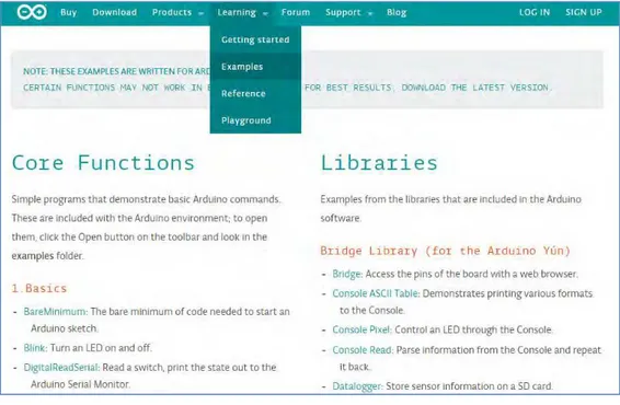
For software development, the programming for Arduino is using Arduino Coding Software and for circuit design, this project is using „ISIS‟ software. In the software, the circuit created can be simulated and the parameter can be adjusted. This ultrasonic sensor using in this project can detect range from 2cm up to 400cm (13ft). Arduino provides a number of libraries that makes an easy steps in programmed the microcontroller. More useful of Arduino are things such as being able to set I/O pins to PWM at a certain duty cycle using a single command or doing Serial communication.
Figure 1.1: Arduino Libraries
1.4 Project Methodology
There are three main parts to complete this project System to detect the range
System that function as an alert
The component use in this system is buzzer and LED. Buzzer produce „beep‟ sound and LED indicate the level of range.
System to display
Using LCD to display the range that detect by ultrasonic. If more than 50cm, the LCD display show “SAFE DISTANCE”, 20cm until 11cm , the display show “BEWARE!!” and less than 10cm, LCD display “BRAKE!!”. Else, LCD display show the distance in centimetre.
1.5 Report Structure
Chapter II
Literature Review
2.1 Chapter overview
2.2Previous Project
2.2.1 Distance Measuring (Hurdle Detection System) for Safe Environment in Vehicle through Ultrasonic Sensor Rays. [3]
Distance Measuring (Hurdle detection System) for Safe Environment in Vehicles through Ultrasonic Rays show the development to secure the movement of car or security of driver and vehicle against different hurdles. These projects use four units of ultrasonic sensors which is located at the left side, right side, back side and front side. This is important to achieve the objective because in this journal they want to provide safe environment on car surrounding. Each sensor has one transmitter and one receiver. The transmitter of each sensor will continuously transmit the signals. When these signals will collide with any object and will be reflected back, the receiver of sensor will catch these reflected signals and forward them to the computer on port 889 of parallel port. To find out the object on the side of car, the signal is send to processing unit through parallel ports. Each side or receiver has its own address which is unique. Through this uniqueness or address the proposed method finds out the side of object (Hurdle). In ultrasonic sensor the power is directly proportional to range of ultrasonic sensor. The weakness of this project is there have no alert system as a safety reason because the main objective of this project is to detect the coming of hurdle around a car. For an enhancement from this project, Car Security Alert System has built an alert system to alert the driver when the hurdle is coming.
2.2.2 Car Anti-Collision and Intercommunication System using Communication Protocol [1]
8
keeps reducing, indicating that the front car is coming closer to the current CAR then the microcontroller will start applying brakes until the distance is within safe parameters. This process will continue in a loop until the car stop moving. In this way we can ensure that a safe distance is always maintained between the two cars and thus Accident can be avoided. The three IR sensors are interfaced which are connected to the three sides of the car to detect any proximity to the car. The IR sensor will give a pulse to the microcontroller. The microcontroller will turn on the buzzer which will alert the driver in time to avoid the accident. This project was performed by using ARM7 processor. The weakness of this project is the driver is not allowed to increase speed manually if the security systems detect an obstacle. So, it give risk to driver if want to overtake the front car because the system not allowed car to increase the speed.
Figure 2.1: Communicating between cars
2.2.3 Ultrasonic anti crashing system for automobiles [2]
is using PWM to slow down the motor. This feature varying duty cycle of digital wave and gives its corresponding analogue value to one of the pins controlling the motors. This pin decides the speed of the motor, thus a regulation in speed is achieved. This system also use buzzer to alert driver. Weakness of this project is there have no LCD display to show the distance and have no LED to notify the level of distance. Besides that, controlling the speed will affect the acceleration during overtake the car in front and it will bring the car in high risk because of this system. So, for the enhancement, the LCD display and LED was added to the system.
2.3Hardware
2.3.1 Liquid Crystal Display
To read the output indicator, Liquid Crystal Display (LCD) was used. For a show-up measurement or range of readings, LCD display panel is better choice because it may show the features other than the measurement readings. LCD component is specifically designed to use with microcontrollers such as Arduino, which means that it cannot be activated by standard IC circuits. It is used to display a different message on a small liquid crystal display. It can display a message in two lines with 16 characters each. It displays all the letters of the alphabet, Greek letters, punctuation, mathematical symbols. Other useful features include automatic message shift (left and right), cursor appearance, LED rear lights and etc. There are a total of 16 pin on the display include the pin for brightness adjustment. The VO pin is connect to potentiometer for brightness adjustment. Besides that, it can connect to GND if don‟t want to connect it with potentiometer. [4]
10
2.3.2 Arduino
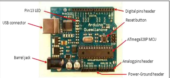
Arduino is an open-source physical computing platform based on a simple microcontroller board, and a development environment for writing software for the board. Arduino can be used to develop interactive objects, taking inputs from a variety of switches or sensors, and controlling a variety of lights, motors, and other physical outputs[8]. For this project, Arduino used the ultrasonic sensor as the input and for the output, LED, LCD display, and buzzer was used. There are many type of Arduino such as Arduino UNO R3, Arduino Mini, Arduino Mega, and Arduino nano etc. For Car Security Alert System, the Arduino Uno R3 was used due to easier to get in the market. Arduino projects can be stand-alone, or they can communicate with software running on computer. The analog output pins are located on the bottom-right six-pin female connector labelled as “ANALOG IN 0-5”. The digital-only pins are located on the top labeled “DIGITAL 0-13”. For this project, the all the digital pin was used except the Tx, Rx, and GND pin. [5]
Figure 2.3 : Arduino Structure
If not, the circuit will not run properly.On the board is also a single reset button that causes the program to restart when pressed, and two more LEDs that flash as data is passed back-and-forth over the USB connection.
The board is most often powered from the USB connector on the upper-left side during software development. The USB connection is the programming link over which programs compiled on the computer are transferred to the MCU. This connection also may be used to exchange data between the board and the computer. The Arduino board comes with a single LED, often called the Pin 13 LED because it is electrically connected to Digital Pin 13 This LED is the board's only built-in indicator accessible to programs.
2.3.2.1 Advantage of Arduino [8]
Inexpensive - Arduino boards are relatively inexpensive compared to other microcontroller platforms such as PIC. For example is Arduino Uno R3 that used in this project that only costing around RM70.
Cross-platform - The Arduino software runs on Windows, Macintosh OSX, and Linux operating systems. Most microcontroller systems are limited to Windows. For this project, Arduino is run with the Window 7 Ultimate.
Simple, clear programming environment - The Arduino programming environment is easy to use for beginners, and the coding is quite easy to understand. Besides that, the library of Arduino also provides the coding complete with the schematic circuit to ease the user. In the web of Arduino, the manufacturer provide the step by step setting for first time user such as how to setting the port, and how to verify the coding.
12
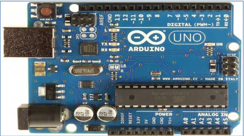
Figure 2.4: Arduino UNO R3
2.3.2.2 Comparison of Arduino type
Arduino Uno R3 Arduino Mega Arduino Nano
Processor ATmega328 ATmega2560 ATmega168
rangefinders are (although acoustically soft materials like cloth can be difficult to detect). It comes complete with ultrasonic transmitter and receiver module [9].
The features of HC-SR04:
● Measuring Angle: 30 degree ● Trigger Input Pulse width: 10uS ● Dimension: 45mm x 20mm x 15mm
14
Time = Width of Echo pulse, in uS (micro second) ● Distance in centimetres = Time / 58
● Distance in inches = Time / 148
● Utilize the speed of sound, which is 340m/s
In this project, the time is divide with 58 in the Arduino coding because the distance measure in centimetre.
Figure 2.5 : Cycle of wave
2.3.3.1 Comparison of distance sensor in market
Figure 2.7: Connection of ultrasonic sensor
16
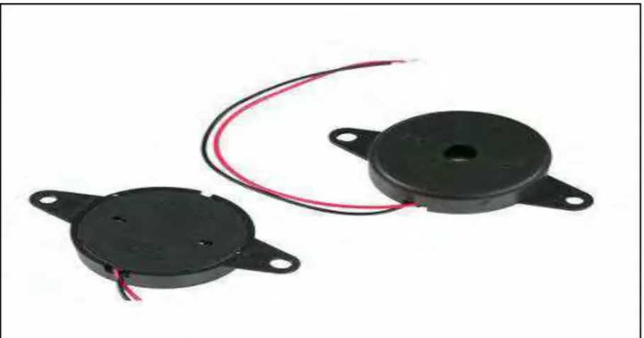
2.3.4 Buzzer
A buzzer defines as a mechanical, electromechanical, magnetic, electromagnetic, electro-acoustic or piezoelectric audio signalling device. It produce tone depend on the oscillating of the electronic circuit. Besides that, it also can operate by using other audio signal source [10]
2.3.4.1 Types of Buzzers
There have several types of buzzers in market that suitable for this project. The buzzer can be divide due to it categorized. For example the buzzer can be categorize by Type, Sound Level, Frequency, Rated Voltage, and Dimension. The several types of buzzer available in market such as Electro-Acoustic, Electromagnetic, Electromechanic, Magnetic and Piezo.
Figure 2.9: Connection of buzzer
Figure above show the connection of buzzer on the ISIS software. The positive terminal of buzzer is connect with 220Ω resistor and the negative terminal of buzzer is connect to pin 4 of Arduino.
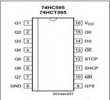
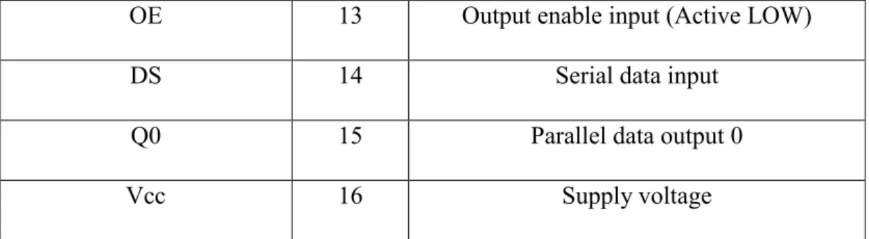
2.3.5 74HC595 IC
18
Figure 2.10: Pin Configuration
Symbol Pin Description
Q1 1 Parallel data ouput 1
Q2 2 Parallel data ouput 2
Q3 3 Parallel data ouput 3
Q4 4 Parallel data ouput 4
Q5 5 Parallel data ouput 5
Q6 6 Parallel data ouput 6
Q7 7 Parallel data ouput 7
GND 8 Ground (0V)
Q7S 9 Serial data output
MR 10 Master reset (Active LOW)
SHCP 11 Shift register clock input
OE 13 Output enable input (Active LOW)
DS 14 Serial data input
Q0 15 Parallel data output 0
Vcc 16 Supply voltage
Table 2.4: Pin Description of 74HC595n
2.4Software
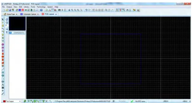
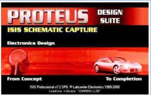
2.4.1 Proteus Design Suite
20
Figure 2.11: ISIS interface
Figure 2.12: ARES interface
Other general features of Proteus 8 include: Runs on Windows XP onwards.
Automatic wire routing and dot placement/removal.
Total support for buses including component pins, inter-sheet terminals, module ports and wires.
Fully configurable Bill of Materials reporting.
Live netlisting to the ARES Layout module and additional netlist outputs to suit other PCB layout tools.
Figure 2.13: Proteus Design Suite
2.4.2 Arduino Coding software
22
Chapter III
Methodology
3.1 Introduction
This chapter explains about the project methodology for Car Security Alert System through analysing on conceptual design, development, and implementation of ultrasonic sensor HC SR04 as the input for the system while the output is the LCD display, LED, and buzzer as the alert system.
24
3.2 Project Planning
Project planning is important to make sure the project can be done within the duration. Project planning which is implemented at the initial stage of project. The Gantt chart present every step done in the project and make sure the project done as the expectation time needed.
3.3 Project Flowchart
Figure 3.1 Start
Literature Review and Research
Hardware design and
development Software design and development
Circuit
testing Soft. testing
Figure 3.2 show the flow of project implementation start from the research until software and hardware development. The first step in this project implementation is by do a research about the quotation of the project. It was done by reading the journal. From there, it shows the idea how to develop the project. The second step is design the circuit for project. In this phase, the entire component used was listed. The input, controller and output was determined and constructed in protoboard by refer to the schematic of the circuit. After completely designed the circuit, the simulation run on circuit. In this phase, there was two stage for simulation. The first one is computerised simulation and second one is on-board simulation. It has done by connect the circuit with power source. The next step is construct programming for Arduino. Once it successfully verified, load the program into Arduino and run the circuit that connected to Arduino.
3.4.1 Circuit Development
The circuit development start from determine the component need for circuit development process. This job can be done by do a research and study about previous project. After component list was determined, the next process is circuit construction by using ISIS software. By using this software, the simulation of circuit can be done and the circuit can be transfer to ARES for PCB footprint purpose.
28
Table 3.1 3.4.1.2 Etching Process
Figure 3.3
Start process PCB Fabrication
Briefing regulation and safety in lab
In order to obtain a suitable PCB layout for fabrication process, the circuit simulated using Proteus requires some modification. This is because some of the components that were used in the simulation using Proteus cannot be implemented while constructing the PCB Layout as it‟s not available. As an example, animated LED is used while conducting the Proteus simulation as it aids in showing the functionality of the circuit. On the other hand, for constructing the PCB layout, the specific component turns out to be unavailable. Therefore, to attain a suitable PCB foot print a connector is implemented instead of LED.
Figure 3.4
List of component
30
Figure 3.5
ISIS provides the development environment for PROTEUS VSM, the revolutionary interactive system level simulator. This product combines mixed mode circuit simulation, micro-processor models and interactive component models to allow the simulation of complete micro-controller based designs. ISIS provides the means to enter the design in the first place, the architecture for real time interactive simulation and a system for managing the source and object code associated with each project. In addition, a number of graph objects can be placed on the schematic to enable conventional time, frequency and swept variable simulation to be performed. [11]
Figure 3.6
For fabrication process involved many step and one of the step is printed PCB layout on transparent plastic that compatible with UV process. After the circuit printed on transparent paper, it was attached to UV PCB board.
32
Figure 3.8: UV PCB Board
The UV PCB Board has a layer of protection and it must remove in the dark room condition. The printed PCB layout was rubbed together with the PCB Board and then the board was put on the UV machine. This machine will vacuum the board to make sure the printed PCB layout stick properly with PCB Board without air bubbles.
Figure 3.10: PCB board in the UV machine
The machine was set to 10 second for UV process. Close the lid and wait until end of 10 second before the PCB going to the next process.
34
After complete the UV process, remove the transparent paper on the PCB. Next process is developing. This process was used developer liquid to develop the board and this process takes around 10 to 15 second. The board was soak in the developer liquid and make sure there have no over develop because it will reduce the thickness of copper. This will break the route on etching process.
Figure 3.12: Developing Process
After done developing process, the board need to rinse with the water.
Figure 3.14: Etching machine
The etching process must be done for three or four times. This is because the copper still cover the board after the first etching process. For this project, the board has done four times etching process before the board are clean from the unwanted copper.
36
Figure 3.15: Immersed Board
The next process is drying process. For this process, there have specific method to dry the board. This process can be done by using cotton to dry the board or using the dryer provided in the lab.
Figure 3.16: Dryer Machine
Figure 3.17: Drilling Process
Figure 3.18: board after drilling process
38
Figure 3.19: Complete soldered board
3.5 Project Chart
Figure 3.20 Start
Ultrasonic detect the range
If >50cm display show„SAFE DISTANCE‟; 21cm until 49cm display show “distance”; 11cm until 20cm display show “beware”
Distance less than 10cm
Display will show „BRAKE!!‟, red LED light up, and Buzzer sound
The chart above is about the sequence of the project running. Started from the HC-SR04 detect the distance, and then it send the data to Arduino. This process is continuous until the sensor detects the range less than 50cm. HC-SR04 use pulse and echo to detect the range. By using this feature, trigger or transmitter spread the wave in 300 angle and once the wave collide with something, the wave is reflect back to
echo or receiver. For the output, if the sensor detect the distance more than 50cm, the display show “SAFE DISTANCE”. If the distance from 21cm to 49cm, the display show the distance in centimetre and if the sensor detect the range between 11cm to 20cm, the display show “BEWARE!!” and the last one is sensor detect the range is less than 10cm, then the display show “BRAKE!!”. For LED, its start to light up once the distance reaches at 40cm. The first level indicates by green colour, second level indicates by blue colour and the third level indicates by red colour. The tonepin for buzzer produce the louder sound every time the LED turns to the next level.
3.5.1 Block Diagram
Figure 3.21
Figure 3.21 shows the block diagram for Car Security Alert System. The ultrasonic sensor is the input where it sent the distance data to Arduino. Arduino take an action as the brain of this system and control all components in this system. For the output, there are three outputs for the system. The first output is LED, second is Buzzer, and the third one is LCD. LED will light up when the ultrasonic detect range
40
Chapter IV
Result and Discussion
4.1 Overview
42
4.2 Testing and Output Result
From the previous chapter, the software and hardware implementation were already discussed. Project methodology, method, and comparison of each journal have been made for enhancement purpose. The ISIS software gives results from the aspect of layout design and fabrication.
4.2.1 Hardware and Prototype of Car Security Alert System
Figure 4.1 shows prototype of the project. The car was equipped with the ultrasonic sensor on the front side and for the output, the LCD display, LED, and Buzzer was placed on the back of the car. The circuit and Arduino were placed in the car while the battery that was functioned to operate the circuit was placed under the car. Some modifications have been done before the circuit and Arduino can fit in the car.
Figure 4.1
the car reach 35cm from hurdle and the next led will light up every 5cm movement of car from hurdle.
Figure: 4.2
Figure: 4.3
44
Figure: 4.4
Figure 4.4 shows the location of the buzzer on the prototype. The positive terminal of buzzer was connected to 220Ω resistor and the negative terminal of buzzer was connected to pin no 4 of the Arduino. The resistor function is to avoid the damaged due to the high flow of current.
The third output as the alert system is 16x2 display. 16x2 represents the sixteen character of horizontal of display and two characters for vertical of display. For LCD display, there has a VO pin connected to potentiometer as the brightness adjuster. For display, there have 3 conditions which more than 50cm, the display will show “Safe Distance”, 20cm to 11cm will show as “Beware” on the display and the last condition is less than 10cm and the display will show “Brake!!”
4.2.2 Experimental
For experimental phase, the projects go through a process which is simulated by using software and On Board testing.
Figure 4.6: Simulation on ISIS
In Figure 4.6, it shows the simulation on ISIS. The circuit was constructed and debug. Using the ISIS software, it can detect if there is any wrong connection and it can‟t simulate unless the wrong connection was repaired. The circuit simulate to verify the functionality of the coding. Eventually, we are able to see if the output display on the LCD screen.
46
Figure 4.7 shows the complete circuit constructed on board. All the VCC and GND are connected to the main controller (Arduino). For Arduino, it contains 14 digital output pin. For secure connection, all precaution steps were taken before the Arduino connected with source. Fail to do so, caused the Arduino and component will be broken. The IC 74HC595N was used as shift register for LED and as the result, the LED shifted due to distance measured by the ultrasonic. Three colour of LED was used to indicate the level of distance. The green colour for “safe distance”, yellow colour indicates for “beware” and red colour means “danger”. Each LED connected with 220ohm resistor to avoid the overflow current through the LED.
Figure 4.8: Arduino Structure
4.2.3 Circuit Design
Figure 4.9: Circuit constructed on ARES
The pin connected to Arduino just put as marked point. After the modification is successfully, the PCB layout was designed using software Proteus 8.0 (ARES). Figure 4.9 shows the footprint for each component. The component must be rearranged by manual method to avoid clash route. For this project, the route size is T60 and the marked point set to C70-30. For this process, avoid using small route and small marker point because it will affect the route during the etching process. The small marker will get in trouble during drilling process because the marker is too small and drill will damage the copper on the marker. For Arduino connection, the pin was replaced with header to get the suitable footprint.
4.2.4 Etching and Circuit
48
Figure 4.10: Complete Drilled Board
The component was placed on the board and soldered. The connection must be checked first to make sure there have no short circuit before the circuit running. This precaution step is important to avoid the faulty component.
Figure 4.11 show the complete soldered board. The black jumper behind the board is to recover the missing route and need to put jumper manually. Every single route must be check using multimeter to avoid the touched route.
Figure 4.12: Component placed on PCB
4.3 Arduino Coding
50
Figure 4.13: Arduino 1.6.0 interface
The Arduino board must be connect to the USB port before the coding can be upload to the Arduino. The port used can be determined on control panel of desktop and to run the Arduino, the port can be selected by clicking at „Tools Port‟. After complete develop the coding, verify it by click the „verify‟ button. If no error, proceed by uploaded the coding.
The figure 4.14 show the coding for Display and declaration on each command has been made to more understanding about the coding. As show in the figure, the display show “Brake” if the distance less than 10cm. The command wrote as „if (distance <= 10)‟. If distance more than 50cm, the Display show “Safe Distance” and the command wrote as „else if (distance >= 50)‟. The „else/if‟ command was used to allows greater control over the flow of code than the basic if statement, by allowing multiple tests to be grouped together. For example, an analogue input could be tested and one action taken if the input was less than 45, and another action taken if the input was 45 or greater.
Figure 4.15: Coding for Buzzer
52
Trig of SR04 received a pulse of high (5V) for at least 10us, this initiated the sensor to transmit out 8 cycle of ultrasonic burst at 40 kHz and wait for the reflected ultrasonic burst. When the sensor detected ultrasonic from receiver, it will set the Echo pin to high (5V) and delay for a period (width) which proportion to distance. To get the distance in cm, the time was divided with 58.
Figure 4.17
4.4 Cost for whole project
Table 4.1: Cost for Whole Project
4.5 Discussion
After testing has been made rigorously and all components function properly, it is clear that "Car Security Alert System" achieve the objective. However a few challenges have been countered while developing this project.
The first challenges are developing process of prototype. The structure of RC car body is hard and need to use drill to place the output component. This is important because the prototype part need to develop with nice and tidy to make it more interested. The bigger PCB used also give some trouble while fitting into the RC car body structure. The RC car body need to modify by cutting some part until the PCB board and Arduino are fitted into the RC car.
54
about the Arduino coding provided in the library of Arduino. Even the coding was provided, it need to modify as to fulfil the requirement of the system.
Chapter V
Conclusion
5.1 Introduction
II
5.2 Conclusion
As the conclusion, the project objective “To design an alert system for the driver at certain distance of hit” has been achieved. As the project designed, the buzzer and LED‟s were functioned to give an alert to driver when they were reached the distance which declared as distance of hit. Besides that, the display also functioned as the notification which show the distance status and also show the distance in centimetre. The Arduino UNO as a microcontroller to control all components and the Arduino software was used as the coding development software in ways to complete the “Car Security Alert System” project. As the conclusion, this project is a successful because all objective managed to be achieved at the end of the research and "Car Security Alert System" has successfully been developed.
5.3 Recommendation
Several improvement and innovation can be added to the current project to enhance its functionality. The first improvement can be made is by adding the vibrator to make the driver more alert. This feature can be install on the driver‟s seat and the driver will get an alert by vibration if the car reach dangerous distance.
Another improvement that can be made on this project is „speed switch‟ for the system. The current problem in Car Security Alert System is the alert system always operates and this makes trouble when the car in traffic jammed. The buzzer and LED will always operate and this will make the driver feeling uncomforted with the system. In order to overcome this problem, the speed switch can be implement in this project. This system‟s function is switch on the alert system when the speeds reach 30KM/H and below the stated speed, the alert system will automatically switch off. With this improvement, the system would provide a more effective outcome to this project.
Reference
[1] Triveni Shinde, Car Anti-Collision and Intercommunication System using
Communication Protocol, International Journal of Science and Research
(IJSR), June 2013
[2] Amrutha S Raibagi, Surabhi Anand, and Swetha R, Ultrasonic anti crashing
system for automobiles, International Journal of Advanced Research in
Computer and Communication Engineering, April 2013
[3] Muqaddas Bin Tahir and Musarat Abdullah, Distance Measuring (Hurdle
detection System) for Safe Environment in Vehicles through Ultrasonic Rays,
Global Journals Inc. (USA), Feb 2012
[4] Julyan Ilett,( Feb 1997) “How to use intelligent LCDs” (online), Available: http://www.cytron.com.my/p-ds-lcd-162a-b
[5] Laura Domela,( October 14, 2013 ) “Arduino creator explains why open
source matters in hardware” (online), Available:
http://www.eejournal.com/archives/fresh-bytes/arduino-creator-explains-why-open-source-matters-in-hardware-too/
[6] LabCenter Electronic, What is Proteus VSM (online), Available: http://www.labcenter.com/products/vsm/vsm_overview.cfm
[7] General Road Accident Data in Malaysia (1997 – 2014), MALAYSIAN INSTITUTE OF ROAD SAFETY RESEARCH (MIROS), 2 June 2015 [8] Arduino, Overview of Arduino Uno (online), Available:
http://www.arduino.cc/en/Main/ArduinoBoardUno
[9] Cytron Technologies (May 2013), HC SR04 User's Manual, V1.0 [10] Future Electronic, What is buzzer (online), Available:
http://www.futureelectronics.com/en/passives/buzzers.aspx
Appendix A byte possible_patterns[9] = { B00000000,
XVII
duration = pulseIn(echoPin, HIGH); distance = (duration/2) / 58.2; lcd.setCursor(0, 0);
lcd.print("Distance: ");
if (distance <= 10) //Display Brake {
Serial.println("Brake"); lcd.setCursor(10, 0);
else if(distance >= 50) //Safe Distance {
Serial.print(distance); Serial.println(" cm"); lcd.setCursor(10, 0); lcd.print(" "); lcd.setCursor(0, 1);
lcd.print("Safe Distance"); }
else if (distance >= 11 && distance <= 20) {
Serial.println(" cm"); lcd.setCursor(10, 0); lcd.print(" "); lcd.setCursor(0, 1); lcd.print("BEWARE!!!"); }
else {
Serial.print(distance); Serial.println(" cm");
else if (proximity >= 3 && proximity <= 4) {
tone(tonePin, 1000, 200); }
else if (proximity >= 5 && proximity <= 6) {
tone(tonePin,5000, 300); }
XIX
tone(tonePin, 200000, 300); }
shiftOut(dataPin, clockPin, MSBFIRST, possible_patterns[proximity]); digitalWrite(latchPin, HIGH);
XXI