UNIVERSITI TEKNIKAL MALAYSIA MELAKA
DEVELOPMENT OF CIM CONTROL
SYSTEM USING PLC
Thesis submitted in accordance with the requirement of the National Technical
University College of Malaysia for Degree of Bachelor of Engineering
(Honours) Manufacturing (Robotic and Automation)
By
Hassanul Sazali bin Ahmaddin (B050310088)
i
SESI PENGAJIAN : _______________________
Saya _____________________________________________________________________
mengaku membenarkan t esis (PSM/ Sarj ana/ Dokt or Falsaf ah) ini disimpan di Perpust akaan Universit i Teknikal Malaysia Melaka (UTeM) dengan syarat -syarat kegunaan sepert i berikut :
1. Tesis adalah hak milik Universit i Teknikal Malaysia Melaka .
2. Perpust akaan Universit i Teknikal Malaysia Melaka dibenarkan membuat salinan
unt uk t uj uan pengaj ian sahaj a.
3. Perpust akaan dibenarkan membuat salinan t esis ini sebagai bahan pert ukaran
ant ara inst it usi pengaj ian t inggi.
(Mengandungi maklumat yang berdarj ah keselamat an at au kepent ingan Malaysia yang t ermakt ub di dalam AKTA RAHSIA RASMI 1972)
(Mengandungi maklumat TERHAD yang t elah dit ent ukan oleh organisasi/ badan di mana penyelidikan dij alankan)
(TANDATANGAN PENULIS)
* Tesis dimaksudkan sebagai t esis bagi Ij azah Dokt or Falsaf ah dan Sarj ana secara penyelidikan, at au disert asi bagi pengaj ian secara kerj a kursus dan penyelidikan, at au Laporan Proj ek Sarj ana Muda (PSM). ** Jika t esis ini SULIT at au TERHAD, sila lampirkan surat daripada pihak berkuasa/ organisasi berkenaan dengan menyat akan sekali sebab dan t empoh t esis ini perlu dikelaskan sebagai SULIT at au TERHAD.
HASSANUL SAZALI B. AHMADDIN
DEVELOPMENT OF CIM CONTROL SYSTEM USING PLC
2002-2007
√
POS 1, Kampung Baru, Seri Gading, 83300, Batu Pahat,
Johor
ii
1
DECLARATION
I hereby, declared this thesis entitled “Development of CIM Control System Using PLC” is the results of my own research except as cited in
references.
Signature : ……….
Author’s Name : ………
Date : ………
iii
2
APPROVAL
This thesis submitted to the senate of UTeM and has been accepted as fulfilment of the requirement for the degree of Bachelor of Manufacturing Engineering (Honours)
(Robotic and Automation). The members of the supervisory committee are as follows:
……….. (MR AZRUL AZWAN BIN ABD. RAHMAN)
Main supervisor
iv
3
ABSTRACT
v
4
ABSTRAK
vi
5
DEDICATION
Special dedication to:
My father, Ahmaddin bin Sarpin; mother, Selasiah Binti Arsal; sister, Norul Wahiddah; brothers, Hassanul Hakimi and Hassanul Amirul Amin who are very concern, understanding, patient and supporting. This project and success
vii
6
ACKNOWLEDGEMENT
I would like to thanks everyone that have involve in the making of this thesis and to those who have given generous contributions within the period of this thesis development to fulfill the requirement of the Degree of Bachelor of Engineering (Honours) Manufacturing (Robotic and Automation) program.
Here I would like to express my deepest appreciation to my supervisor, Mr. Azrul Azwan Bin Abd. Rahman, whose have given such effort in helping and support to complete this thesis. His constant guidance and support during my thesis writing is invaluable to me. His continuous direction and opinion regarding the flow of the project has a mass contribution to achieve the objective of the project. Furthermore, the guide and help of him on how to make this thesis a more effective reference are followed with my sincere gratitude. And not to forget the college that had provide me with all the studies equipment of this thesis project.
I also would like to thanks my parent, all my friends and lecturers who have done a lot of things and helped me to fulfil and finished this thesis. I also like to send my best of luck to everyone whom have and will take the final year project and hopefully they can complete and finished their project accordingly.
Finally I hope that with this project it can be used to help and improve for human life standard. Not just in the industrial but for everyday life.
viii
7
TABLE OF CONTENTS
DECLARATION II
APPROVAL III
ABSTRACT IV
ABSTRAK V
DEDICATION VI
ACKNOWLEDGEMENT VII
TABLE OF CONTENTS VIII
LIST OF FIGURES XI
LIST OF TABLES XIV
LIST OF ABBREVIATIONS, SYMBOLS SPECIALIZED NOMENCLATURE XV
CHAPTER 1
INTRODUCTION 1
1.1 Problem Statement 3
1.2 Objectives of the Project 3
1.3 Scope of Project 3
1.4 Project Planning 4
CHAPTER 2
LITERATURE REVIEW 6
2.1 Introduction to Computer Integrated Manufacturing (CIM) 6
2.1.1 CIM activities 7
2.1.2 Design of the CIM system 9
2.2 Introduction to Conveyor System 13
ix
2.1.1.1 Powered skate wheel, roller and strand conveyor group 14
2.1.1.2 Belt conveyor concept 15
2.2.2 Operational Philosophy of standard manufacturing conveyor
system 16
2.2.3 Basic Components of conveyor system 16
2.3 Introduction to PLC 26
2.3.1 PLC compared with other control systems 47
2.3.2 Advantages of PLCs 48
2.3.3 Automation and PLC programming 50
2.3.4 PLC communication 52
2.3.4.1 Siemens PLC's 52
2.3.5 Siemens PLC-SIMATIC S7-200 54
2.4 Programming software (STEP 7) 54
2.4.1 Creating Program with Binary Logic 55
2.4.1.1 Integrate the hardware and software 56
2.4.1.2 Basic Procedure Using STEP 7 58
2.4.1.3 Choosing Ladder Logic, Statement List, or Function Block
Diagram 59
2.4.1.4 SIMATIC STEP-7 Micro/WIN 62
CHAPTER 3
METHODOLOGY 64
3.1 Description of the stages. 64
3.1.1 Phase one: Planning 64
3.1.2 Phase two: Identification of requirement 65
3.1.3 Phase three: Designing 65
3.1.4 Phase four: Construction 65
3.1.5 Phase five: Implementation 66
3.2 Experimental Setup 68
x CHAPTER 4
RESULT 69
4.1 DEVELOPMENT 69
4.2 IMPLEMENTATION 71
4.3 RESULT 72
4.3.1 Programming 73
4.3.1.1 Ladder diagram programming 73
CHAPTER 5
DISCUSSION 78
5.1 Analysis 78
5.1.1 Hardware Analysis 79
5.1.1.1 Early stage 79
5.1.1.2 Conveyor analysis 81
5.1.2 Program Analysis 90
5.1.2.1 Program task and network analysis. 92
5.2 Program and network discussion 94
CHAPTER 6
CONCLUSION & RECOMMENDATION 106
6.1 Recommendation and suggestion 106
6.2 Observation of the project 107
6.3 Conclusion 108
REFERENCE 109
xi
8
LIST OF FIGURES
Figure 2.1: Relations of CIM activities (Rembold 1993) 8
Figure 2.2: CIM processes 9
Figure 2.3: A framework of the design and implementation of CIM (Tariq Masood
and Iqbal Khan, 2004) 11
Figure 2.4: History of CIM (Tariq Masood and Iqbal Khan, 2004) 12 Figure 2.5: Simple conveyor line with control panel (Siemens Energy & Automation,
2004). 14
Figure 2.6: A sample picture of a motor (stepper) 19 Figure 2.7: Picture (a) show the 3 phase motor and (b) show the inside of the motor
19 Figure 2.8: Safety device that used in the conveyor and industries 21 Figure 2.9: Showed a flow chart of key decisions in the selection of a safety switch22 Figure 2.10: Types of sensor used in conveyor system 23 Figure 2.11: Shows that the comparison between hardwiring circuit with the ladder
circuit. Picture (a) is the hardwiring circuit and picture (b) is the ladder
circuit. 24
Figure 2.12: Shows the connection of control circuit from the power circuit 25 Figure 2.13: Relationship between PLC and it components 26 Figure 2.14: Show that the Basic PLC operation module block. 27 Figure 2.15: Input/output (I/O) component connected to PLC 28
Figure 2.16: Basic PLC terminal 29
Figure 2.17: Input X1 is energized 29
Figure 2.18: Output Y1 energized and what happen inside the PLC 30 Figure 2.19: Communication between hardware and software 31 Figure 2.20: How the software simulate and energized the hardware 32 Figure 2.21: Pushbutton is unactuated (not being pressed) 34
Figure 2.22: Switch is shown actuated (pressed) 35
xii
Figure 2.25: Start button is pressed and actuated the output 39
Figure 2.26: When the start button is released 40
Figure 2.27: To stop the motor, must momentarily press the "Stop" pushbutton 41 Figure 2.28: The motor, however, will not start again until the "Start" pushbutton is
actuated 42
Figure 2.29: Reversal of logic between the X2 "contact" inside the PLC program and the actual "Stop" pushbutton switch 43 Figure 2.30: Emulate the function of a three-input NAND gate 45 Figure 2.31: The lamp remain lit so long as any of the pushbuttons remain
unactuated (unpressed) 46
Figure 2.32: Connection between the CPU with the input/output and PC 51 Figure 2.33: Programming cable for OPxx display series 52 Figure 2.34: User Communication and Modem Communication System 53 Figure 2.35: Illustration of AND logic function. 55
Figure 2.36: Illustration of OR logic function. 55
Figure 2.37: Illustration of SR function. 56
Figure 2.38: Connection between the STEP 7 software with other output. 57 Figure 2.39: How to create the STEP 7 programming 58 Figure 2.40: Shows the input output terminal module 59 Figure 2.41: Example of ladder logic diagram, statement list and function block
diagram 61
Figure 2.42: CPU operating cycle. 61
Figure 2.43: The sequence of PLC programming using SIMATIC Step-7 MicroWin. 62 Figure 3.1: Flow chart of method and working procedure 67 Figure 5.1: Specification and type of motor are also attached at the motor cage 84 Figure 5.2: Pneumatic stoppers and proximity sensors 84
Figure 5.3: “U” shape conveyor design 85
xiii
Figure 5.8: Pneumatic valve is using electrical solenoid 88 Figure 5.9: All wiring must do properly and labelled using cable mark. This is for
easy reference and checking 89
Figure 5.10: Only with the supervision of authorised personnel can modified the
wiring 89
xiv
LIST OF TABLES
Table 1.1: Gantt Chart 4
Table 2.1: Motor Matched sizes rating (Siemens Energy & Automation, 2004) 18 Table 2.2: Utilization Category with IEC description (Siemens Energy &
Automation, 2004) 19
Table 2.3: Types of sensors, advantages and disadvantages and applications 23 Table 2.4: Programming language and suitable user group with it application 60
Table 4.1: List of Input Output (I./O) address 72
xv
10
LIST OF ABBREVIATIONS, SYMBOLS
SPECIALIZED NOMENCLATURE
CAD - Computer-aided Design
CAM - Computer-aided Manufacturing CAQ - Computer-aided Quality Control
CASA - Computer and Automation Systems Association CIM - Computer Integrated Manufacturing
CNC - Computer Numerical Control CPU - Central Processing Unit
CRT - Cathode Rays-tube
DIN - Deutsches Institut für Normung (German Institute for Standardization)
DNC - Direct Numerical Control
EEPROM - Electrically Erasable Programmable Read-Only Memory
FBD - Function Block Diagram
FMS - Flexible Manufacturing System
ft - Feet
I/O - Input/output
IEC - International Electrotechnical Commission
in - Inch
LAD - Ladder Logic
LCD - Liquid Crystal Display MPI - Multi Point Interface
NC - Numerical Control
NEMA - National Electrical Manufacturers Association PLC - Programmable Logic Controller
xvi
SKU - Stock Keeping Unit
SME - Society of manufacturing Engineers
SR - Set / Reset
STL - Statement List
1
1
CHAPTER 1
INTRODUCTION
In this chapter it will be discussed about the introduction of this project where it will be focusing on the background of the project. As the title of the chapter, this also includes the basic and overall description of the project. To knows and making a research what the important things to do is by finding it problem and does it have been research before or similar to it. In this chapter also will telling the objectives and the purpose of this project.
This project is actually to make an analysis and development of the programmable logic controller (PLC) for the computer integrated manufacturing (CIM) which mean that by making a conveyor line and adding the (CIM) behaviour. The used of PLC in this project is to control the system and develop an automated system. This project also will be combining with other final projects (workstation) and this project (conveyor) will be the main features of the project. Other projects that will involve in this project are the feeder station, automatic colour sorting station, quality inspection station and the assembly station.
2
and there are a lot of things to be considered when trying to assembly the LCD. Before starting with the programming with the PLC controller, the main thing needed here is the structural of the conveyor system and it workflows.
Conveyor system is the medium to make the product transferred or moved from one destination to other. This project can only be success if the conveyor workflows are running smoothly and nothing problems is happens. Beside as the transferring device, conveyor also gives the highest impact to the industry. This because the chosen of conveyor like it length, types and application are playing a big role in choosing the conveyor system. The environmental of the working area that the conveyor will be operated is also depend and must be consider as important part in making a conveyor system. For an example, if the conveyor are used in the ice cream factory it need to be made from high quality stainless steel or by using a coated steel to prevent the conveyor from rusting. Component of the conveyor also must be made from non-rusting steel and high quality because it needs to stand the temperature under 0 0C. Conveyor system can make the whole system failure to operate accordingly if the conveyor is malfunction or the programming of the conveyor system itself is wrong. This can cause the company to lose a lot of time and production.
3 1.1Problem Statement
Computer integrated manufacturing is a large area in manufacturing and it combine the use of activities. Even all the machine is controlled individually or synchronously but the main operation to move the product from station to station and from machine to other machine is controlled by the PLC. The main problem now is how to develop a new PLC programming and analyse it movement and operation. This have been the problem because there are a lot of things got to be consider and not just look at the conveyor operation but also all the equipment, tools, controller, it state, cycle time and working procedure. The PLC programming is depends on the conveyor system that will be made as the main system to move the product. So here what the most important is by making the design of the conveyor and know the station is taking places. After all the design is complete and have been analyse then the conveyor working procedure can be made to set the PLC programming as to made it autonomous.
1.2Objectives of the Project
The objective of this project is to integrate the conveyor system in CIM by using PLC controller to control the working procedures. Also to develop an integrated conveyor system that will be attached with assembly stations and a system that can be improved for further research.
1.3Scope of Project
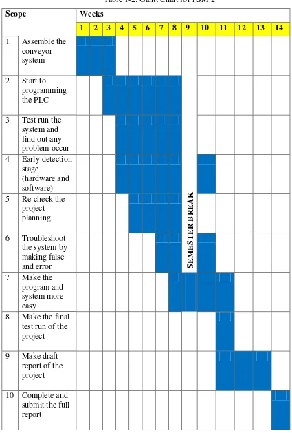
4 1.4Project Planning
Table 1-1: Gantt Chart for PSM 1
5
Table 1-2: Gantt Chart for PSM 2
6
2
CHAPTER 2
LITERATURE REVIEW
2.1Introduction to Computer Integrated Manufacturing (CIM)
7
provides the electronic part images, and CAM provides the facility for toolpath cutters to take on the raw piece.
2.1.1 CIM activities
In the CIM there are some activities that lead to the making of the CIM system itself. The definition of the computer terminology in manufacturing are include the,
• CAD (Computer-aided Design) – this activity comprises computer supported design, drafting, and engineering calculation. Since engineering is also involved in product testing, NC program generation, and other computer supported functions, the term CAE (Computer-aided engineering) is often used.
• CAP (Computer-aided planning) – this activity is concerned with the computer-aided generation of a technological plan to make the product. The process plan describes the manufacturing processes and sequence to make the part.
• CAM (Computer-aided manufacturing) – this activity defines the functions of a computer to control the activities on the manufacturing floor, including direct control of production equipment and management of material, cutting tools, fixtures and maintenance.
• CAQ (Computer-aided quality control) – this activity combines all ongoing quality control work of a manufacturing system. In some cases it is termed CAT (Computer-aided testing), which is somewhat restrictive in its meaning.
• CAD/CAM designates the sum of the activities CAD, CAP, CAM, and CAQ.
• PP&C (production, planning and control) – this function is the organisational activity of CIM. It is concerned with manufacturing resources planning, materials requirement planning, gross requirement planning, time phasing, order release, and manufacturing control.