Functional Nanofiber and Nanocoating
for Biological Application
August 2018
A thesis submitted in partial fulfilment of the requirements for the degree of
Doctor of Philosophy in Engineering
Keio University
Graduate School of Science and Technology
School of Integrated Design Engineering
Keio University
Graduate School of Science and Technology
School of Integrated Design Engineering
Functional Nanofiber and Nanocoating
For Biological Application
by
Park, Jun-Yong
A T
HESISS
UBMITTED INP
ARTIALF
ULFILLMENT OFTHE
R
EQUIREMENTS FORTHED
EGREEDoctor of Philosophy
APPROVED, THESIS COMMITTEE:
Shiratori, Seimei
Citterio, Daniel
Tsukada, Kosuke
Ryo, Sudo
i
for Biological Application
Abstract
In recent years, nanoparticle technology has provided a key focus for research not only for industrial applications, but also extensive research for medical applications, where benefits to improve both quality of human life and length of life are being investigated. Furthermore, these medical applications offer advantages with respect to mass production for innovative techniques relating to surface coatings, gene therapy techniques, wound therapy products and medical device coatings. These biological innovations need to address a variety of challenges such as non-toxicity, biodegradability and biocompatibility of products; of these challenges, human-safety is the paramount concern. Therefore, the development of nanoparticle coatings for biological application with appropriate human-safety characteristics is a focus of medical research. This paper demonstrates a successful biological application of a functionalized coating with materials acceptable for human use. More specifically, the blood coagulation property of a calcium carbonate composite with natural polymer chitosan and alginate produced via a multi-layer by layer-by-layer method is utilized in conjunction with the blood coagulability property of biodegradable nanofibers with calcium carbonate and chitosan and also the anti-adhesion properties of a superhydrophobic coating to produce a preventative medical device against tissue adhesion and anti-fouling with a functionalized dynamic omniphobic layer on a metallic surface. The blood coagulability multi-layer
ii
coating offers the potential for diverse medical applications such as particles for spray applications and nanofiber-based biodegradable/biocompatible materials for use in wound dressings, where rapid emergency hemostasis is urgently required. Anti-adhesion/fouling functionalized coatings are suitable for use not only in medical devices, but also applicable for general medical situations, where tissue adhesion and bio-fouling may be relevant. Such functional coatings will be valuable for doctors conducting medical treatment, for manufacturers of medical devices, and also, for various other bio-related industrial applications relevant to the improvement of human life quality.
iii
Design Science, School of Integrated Design Engineering, Graduate School of Science and Technology at Keio University. This work was financially supported by Ministry of Education, Culture, Sports, Science and Technology, Japan and the research grant of the Keio Leading-edge Laboratory of Science and Technology.
First of all, I would like to give my special thanks to Prof. Dr. Kosuke Tsukada, Prof. Dr. Daniel Citterio and Prof. Dr. Ryo Sudo for kindly accepting to be the reviewer and reviewing my Ph.D. thesis. I would like to express my academic supervisor Prof. Dr. Shiratori who provided me to spend five years in his lab and at Keio University. Without his kind help and supervision for all of my research, this dissertation could not have been achieved. I also would like to express Prof. Dr. Sae-Hoon Kim who gave me valuable advices and comments, and motivation.
I deeply acknowledge Dr. Kyu-Hong Kyung. He took care of me and instructed all equipment for experiment and various academic advice, assistance. Without his help, I cannot complete this dissertation. Special thanks also go to Dr. Yoshio Hotta, Dr. Kouji Fujimoto, whose meticulous comments were an enormous help, helpful comments and suggestions to me. I am grateful to all members of the Shiratori lab – current and past, for being sources of inspiration for me.
I appreciate my precious friend Min-Ju Park. She always supported everything. Thank you for my best friends. Jun-Sik Min, Soo-Hyun Park, Ji-Ho Choi, Seung-Hwan Oh, whose had spent good time together in my school life
Finally, I am grateful to my father and mother and younger sister. They gave me a chance to study in a good environment.
iv
Table of Contents
Abstract Acknowledgements List of Figures List of TablesChapter 1. Introduction of this study ... 1
1.1. Fastest blood coagulation ... 2
1.2. Anti-adhesion for tissue adhering ... 3
1.3. Keystone of this study ... 4
1.3.1. Layer by Layer (LBL) self-assembly techniques ... 4
1.3.2. Electrospinning ... 6
1.3.3. Surface Wettability ... 7
1.4. Dissertation overview ... 8
1.5. References ... 12
Chapter 2. Enhancement of Blood Coagulation Calcium Carbonate Composite Mimicking Cuttlefish Bone by Layer-by-Layer Method ... 21
2.1. Introduction ... 21
2.2. Experimental section ... 22
2.2.1. Materials ... 22
2.2.2. Synthesis of calcium carbonate ... 23
2.2.3. Production of calcium carbonate composite ... 23
2.2.4. Measurement of layer thickness and coating material quantity ... 24
v
2.3.2. Analyzing crystal structure ... 26
2.3.3. Coating CaCO3 by the Layer-by-Layer (LBL) self-assembly method. ... 27
2.3.4. Results of layer thickness measurements and coating material quantities ... 28
2.3.5. Results from whole-blood-clotting studies ... 29
2.4 Conclusions ... 30
2.5. References ... 31
Chapter 3. Biodegradable Polycaprolactone Nanofibers with β-chitosan and Calcium Carbonate Produce a Hemostatic Effect ... 36
3.1. Introduction ... 36
3.2. Experimental section ... 38
3.2.1. Materials ... 38
3.2.2. Synthesis of calcium carbonate ... 38
3.2.3. Fabrication of electrospun nanofibers ... 38
3.2.4. Fiber spraying with β-chitosan ... 39
3.2.5. Whole-blood coagulation assessment ... 42
3.2.6. Assessment of coagulation in mouse blood ... 43
3.3. Results and discussion ... 44
3.3.1. Impact of calcium carbonate on blood clotting ... 44
3.3.2. Nanofiber morphology and CaCO3 content... 45
3.3.3. Ultrasonic spray coating versus hand spraying ... 49
3.3.4. Assessment of coagulation in mouse blood ... 55
vi
3.4. Conclusions ... 60
3.5. References ... 61
Chapter 4. Anti-adhesion Functionalized Superhydrophobic Coating for Biological Surface ... 66
4.1. Introduction ... 66
4.2. Experimental section ... 69
4.2.1. Materials ... 69
4.2.2. Weight change and temperature measurements ... 69
4.2.3. Coating on the bipolar forceps tips and stainless-steel plate ... 69
4.2.4. Characterization ... 70
4.2.5. Adhesion force measurements ... 70
4.3. Results and discussion ... 71
4.3.1.Weight and temperature change of the bipolar forceps ... 71
4.3.2. Wettability analysis of surface ... 75
4.3.3.Surface morphology of the coated sample ... 77
4.3.4.Adhesion force measurements ... 78
4.3.5. Discussion and calculation of the adhesion forces between thecoatings... 80
4.4. Conclusions ... 85
4.5. References ... 86
Chapter 5. Anti-adhesion Functionalized Omniphobic Coating for Biological Surface ... 91
5.1. Introduction ... 91
5.2. Experimental section ... 93
vii
5.2.4. Surface wettability ... 94
5.2.5. Durability assessment ... 95
5.2.6.Soft tissue adhesion force measurement ... 95
5.3. Results and discussion ... 97
5.3.1.Effect of coating in surface wettability ... 97
5.3.2. Characterization of film ... 99
5.3.3.Film durability assessment. ... 101
5.3.4. Soft tissue adhesion force measurement ... 104
5.4. Conclusion ... 106
5.5. References ... 108
Chapter 6. Summary and outlook ... 112
viii
List of Figures
Figure 1-1. Time series showing number of biological articles received by Elsevier Scopus (Keyword: Biological). ... 2
Figure 1-2. A schematic of whole blood coagulation process in human-body. ... 3
Figure 1-3. A schematic depiction of film deposition via the LBL self-assembly technique. Reproduced with permission from Ref. 42. ... 5
Figure 1-4. Depiction of the electrospinning ... 7
Figure 1-5. The surface wettability model of hydrophobic surface and hydrophilic surface. Reproduced with permission from Ref. 62. ... 8
Figure 1-6. Overview of dissertation structure ... 11
Figure 2-1. SEM images: (a) CaCO3 without SDS, (b)CaCO3 with SDS (c) Cuttlefish
bone. ... 25
Figure 2-2. XRD patterns of synthesized CaCO3. ... 26
Figure 2-4. QCM frequency shift of β-chitosan and alginate. ... 29
Figure 2-5. Results of whole-blood clotting studies using pig blood. (a) Comparison of various materials. (b) Comparison of different CaCO3 surface structures with
increasing bilayers. ... 30
Figure 3-1. Schematic of the ultrasonic spray machine and a single cycle of the spraying procedure. The ultrasonic spray machine comprised an air pump, an ultrasonic generator, and a syringe pump. The frequency of the ultrasonic pump is controlled by the ultrasonic generator (120 kHz). The syringe pump can adjust flow rate of the
ix
Figure 3-2. Nanofiber fabrication and spraying procedure. Firstly, the nanofiber was fabricated by electrospinning. β-chitosan solution was then sprayed onto the PCL nanofiber and the PCL/CaCO3 nanofiber; nanofiber mats were extracted from the
aluminum foil when they were capable of self-standing. ... 42
Figure 3-3. Whole blood coagulation assessment. Nanofiber mat samples were attached to glass slides under the same conditions as rinsing in the water bath. ... 43
Figure 3-4. Video image capture of blood coagulation process (a) without and (b) with CaCO3 on a glass slide. Red boxes highlight commencement of the blood coagulation
process. ... 44
Figure 3-5. Field emission scanning electron microscope images of (a) the PCL nanofiber and (b) the PCL/CaCO3 nanofiber. ... 47
Figure 3-6. Field emission scanning electron microscope images of nanofibers possessing varying weight ratios (From 1:1 to 1:3). ... 47
Figure 3-7. The result of thermogravimetric (TG) and differential thermal analysis (DTA). ... 48
Figure 3-8. Schematic of the nanofiber fabrication procedure: (a) PCL nanofiber; (b) PCL/CaCO3 nanofiber. Aggregation was observed to occur on the tip of needle during
the PCL/CaCO3 nanofiber fabrication process. ... 48
Figure 3-9. Field emission scanning electron microscope image of soaked fiber mat in a solution of aqueous PBS and mouse blood, between 6 to 24 h. ... 49
x
Figure 3-10. Field emission scanning electron microscope image of β-chitosan on PCL nanofibers after (a) hand spraying and (b) application of an ultrasonic spray machine. The quantity of β-chitosan applied is identical in the two images. However, β-chitosan can be seen to be more homogenous in (b). The black box indicates particle analysis. 51
Figure 3-11. Results of EDX mapping. ... 51
Figure 3-12. Results of FT-IR spectral analysis: (a) wide FT-IR spectrum range (500-4000 cm-1); (b) narrow FT-IR spectrum range (1500-2500 cm-1) (the blue dash line
represents the absorbance peak at 1610 cm-1); (c) narrow FT-IR spectrum range
(500-1500 cm-1) (the red dash line represents the absorbance peak at 875 cm-1). ... 52
Figure 3-13. Results of whole-blood coagulation experiment utilizing pig blood on glass slides. Nanofiber mats were produced via (a) ultrasonic spraying or (b) hand spraying, with all other experimental conditions being equal. ... 54
Figure 3-14. Results of the whole-blood coagulation experiment employing fresh mouse blood. β-chitosan samples represent fibers sprayed ultrasonically for 2.5 ml. ... 56
Figure 3-15. Results from nanofiber mat attachment experiment. (a) Photograph of attachment experiment. PCL nanofiber applied to left-hand side of mouse; PCL/CaCO3
nanofiber sprayed with β-chitosan applied to right-hand side of mouse. (b) Photograph of wound following attachment of PCL nanofiber. (c) Photograph of wound following attachment PCL/CaCO3 nanofiber sprayed with β-chitosan. (d) Photograph of
nanofiber mat following attachment experiment. ... 56
Figure 3-16. Photographs from blood coagulation experiment utilizing mouse blood: (a) PCL nanofiber; (b) PCL nanofiber sprayed with β-chitosan for 2.5 ml; (c) PCL/CaCO3 nanofiber; (d) PCL/CaCO3 nanofiber sprayed with β-chitosan for 2.5 ml.
xi
phenomenon also identified by the hydrophilicity of the surface of (d). ... 57
Figure 3-17. Results of blood contact angle (mouse blood). The blood contact angle was measure for a 1ml droplet of pigs’ blood. ... 59
Figure 3-18. Results of blood contact angle (mouse blood): (a) PCL nanofiber; (b) PCL/CaCO3 nanofiber. Results were obtained while quantities of β-chitosan were
increased up to 7.5 ml. The blood contact angle was measured from a 1 ml droplet of mouse blood. ... 60
Figure 3-19. Results of the blood coagulation test using fresh mouse blood (Corresponding to weight ratio of PCL: CaCO3 and optimum content of β-chitosan).
15 µl of mouse blood was utilized immediately to circumvent blood coagulation. ... 60
Figure 4-1. (a) Image of the adhesion force measurement machine operating on chicken meat. (b) Schematic depiction of the adhesion force measurement machine operation: the stainless-steel substrate was placed on the hot plate; the hot plate was connected to a temperature controller and thermocouple; the meat sample was connected to the clip; the meat sample was balanced at the center of the stainless-steel substrate. To eliminate the ‘pretension’ effect, the stainless-steel substrate and chicken meat were set to the same distance with “0” point adjustment of applied force indicated prior to commencing measurement. Reprinted with permission from Ref. 36. Copyright 2018 American Chemical Society. ... 71
Figure 4-2. Images of bipolar forceps making contact with the 5 different materials: (a) pig liver (14 W); (b) chicken wing blood tube (7.2 W); (c) chicken wing under the
xii
skin (7.2 W); (d) chicken wing muscle (7.2 W); (e) chicken wing skin (7.2 W). Electricity (W) and current time applied varied according requirements to the of the material under investigation. The white scale bar indicates 2 cm. Reprinted with permission from Ref. 36. Copyright 2018 American Chemical Society. ... 73
Figure 4-3. Weight change of bipolar forceps before and after use in the five different materials: (a) pig liver; (b) chicken wing blood tube; (c) chicken wing under the skin; (d) chicken wing muscle; (e) chicken wing skin. The weight of the bipolar forceps was measured three times using a microbalance. After the bipolar forceps had made contact with the five different materials, the weight change of the bipolar forceps was confirmed using the same procedure. Reprinted with permission from Ref. 36. Copyright 2018 American Chemical Society. ... 74
Figure 4-4. Maximum temperature and the temperature increase rate of bipolar tips when applied to the five different materials: (a) pig liver; (b) chicken wing blood tube; (c) chicken wing under the skin; (d) chicken wing muscle; (e) chicken wing skin. The sample surface temperature close to the contact point of the bipolar tips was measured. The temperature increase rate ((maximum temperature − initial temperature) / time) was measured. Reprinted with permission from Ref. 36. Copyright 2018 American Chemical Society. ... 75
Figure 4-5. Wettability analysis of different samples. (a) Contact angle and receding contact angle measurements on the surface of all the samples. Sample 1 was fabricated by spraying 5 ml of hydrophobic silica on the surface followed by drying at room temperature. Sample 2 was fabricated by spraying hydrophobic silica 5 ml of hydrophobic silica followed by drying and spraying again with the same amount of hydrophobic silica (5 ml), (b) Time-lapse photographs of a water droplet bouncing on
xiii
Figure 4-6. Field emission scanning electron microscopy images of Sample 1 (a, c), Sample 2 (b, d). High-magnification images of the coated surface (c, d). Reprinted with permission from Ref. 36. Copyright 2018 American Chemical Society. ... 77
Figure 4-7. Adhesion force measurements with varying surface temperature and maps of surface temperature: (a) 60; (b) 80; and (c) 100 °C. The figures on the left depict the maximum applied force on different modified surfaces at the same surface temperature. The figures on the right depict the relevant maps of the surface temperature obtained by an infrared thermometer camera. In Area 1, the white number represents the surface temperature. Reprinted with permission from Ref. 36. Copyright 2018 American Chemical Society. ... 79
Figure 4-8. Schematic illustration of the adhesion force analysis in the instance where both the coating and meat are held in place by the adhesive effects of the intermediary water. Reprinted with permission from Ref. 36. Copyright 2018 American Chemical Society. ... 82
Figure 4-9. Schematic illustration of adhesion force analysis when the intermediary water is held by the meat but does not adhere to the coating. Reprinted with permission from Ref. 36. Copyright 2018 American Chemical Society. ... 83
Figure 5-1. Schematic diagram of the adhesion force measurement machine. The substrate sample (stainless steel with omniphobic coating) was placed on the hot plate. The hot plate was wired to a temperature controller and thermocouple. The chicken
xiv
meat was connected via the clip. The meat sample was balanced at the center of substrate sample. The chicken meat was contact with the sample for a 30 s period. ... 96
Figure 5-2. (a) Contact angles, (b) sliding angles measured for the fabricated omniphobic films over varying dip speeds and surface temperatures. ... 98
Figure 5-3. (a) AFM images and RMS values over varying dip speeds; (b) contact angle hysteresis resulting from fabricated omniphobic films over varying dip speeds.. 99
Figure 5-4. Film thickness over varying dip speeds. ... 100
Figure 5-5. Results of (a) FT-IR spectrum (400-4000 cm-1); (b) enlarged FT-IR
spectrum (700-1600 cm-1) for peal with sol-gel method measured over varying dip
speeds and coatings. ... 101
Figure 5-6. (a) Contact angles with and without KOH treatment, (b) sliding angles measured for fabricated omniphobic films at a dip speed of 0.7 mm/s on stainless steel over varying temperatures; (c) AFM images and RMS values for different pretreatments (KOH). ... 103
Figure 5-7. TG-DTA analysis of (a) DTMS and (b) DTMS with TEOS. ... 103
Figure 5-8. (a) contact angles following abrasion testing at varying dip speeds, (b) sliding angles following abrasion testing at varying dip speeds. ... 104
Figure 5-9. Soft tissue adhesion force measurements over varying dip speeds and surface temperatures. ... 105
Figure 5-10. Results from repeat peeling measurements with DTMS film and a superhydrophobic surface at 100 °C. The DTMS film was fabricated by varying dip speeds (0.7, 1.4, 2.1, 2.8 mm/s). ... 106
Chapter 1. Introduction of this study
1
Chapter 1. Introduction of this study
Biological developments have evolved rapidly over the last two decades, particularly with respect to the development of applications for human health. The number of biological research articles submitted to publishing house Elsevier has been observed to exponentially increase over the last fifty years (See Figure 1-1). This is particularly the case for research impacting human health, length of life and quality of life with in-depth research occurring in many fields, such as genetics, medical treatment, drug delivery, etc. Medical treatment is now widely available in developed nations. However, over the past decade, a number of serious challenges for adequate medical provision have arisen: natural disasters such as earthquakes and war have resulted in serious traumatic injury for many, while epidemic viral infections such as EBOLA, which causes massive bleeding, have occurred. The prevention of blood loss is crucial first-aid in bleeding situations prior to the arrival of professional emergency medical services. When the human body bleeds, a hemostatic reaction takes place within the body which acts to stop further bleeding. However, wounds may be large and deep and therefore cessation of bleeding can take time, while serious blood loss may be occurring. Under such circumstances, wound dressings and medical assistance are required. These circumstances have led to a dramatic increase in the number of patents for wound dressings. 1 A variety of medical approaches
are employed to enhance hemostasis, such as applying pressure to blood vessels to restrict blood flow, application of direct compressive pressure on the wound itself2,3 and also
wound searing by employment of a medical device to apply hot temperatures to the wound.4
2
Figure 1-1. Time series showing number of biological articles received by Elsevier Scopus (Keyword: Biological).
1.1. Fastest blood coagulation
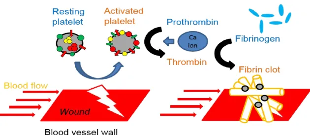
Successful cessation of bleeding entails rapid hemostasis. Figure 1-2 depicts inactive platelets circulating in the blood under normal conditions. Divalent calcium ions are present in human bone and tissue at high concentrations. Calcium ions play an important role in hemostasis by accelerating blood clot formation by facilitating the conversion of prothrombin to thrombin, in addition to catalyzing many other coagulation-related reactions.5 Calcium ions are also an essential factor for blood coagulation.6 Previous
research has described the use of calcium alginate as a wound dressing and membrane.7
Biomaterials with properties such as wound healing and cell attachment are useful for a variety of biological applications.8-10
Chapter 1. Introduction of this study
3
Figure 1-2. A schematic of whole blood coagulation process in human-body.
Rapid hemostasis is essential for saving lives and minimizing blood loss in emergency situations. While prevention of injuries is of paramount importance, the first-aid response is critical in emergency situations. In addition, under such circumstances, since any wound dressing (or membrane) is in direct contact with wound area, it is essential that these dressings comprise materials which are safe when applied to the human-body.
1.2. Anti-adhesion for tissue adhering
Electrosurgery is the application of electrical energy such as high-frequency alternating current or direct current to normal or diseased biological tissue.11 It is used to fulgurate
or control bleeding or cut tissue.12-15 Advantages of electrosurgery include minimal
trauma to patients, negligible pain and rapid recovery. However, healthy tissue can also be burned by the high temperatures elicited by the medical intervention. Since charred tissue adheres to the medical device with each tissue contact, hemostasis fails to occur. To overcome this problem of tissue adhesion to electrosurgical instruments, a variety of approaches have been attempted: addition of anti-inflammatory agents,16,17 addition of
4
antibiotics,18,19 addition of tissue barriers,20-25 addition of fibrinolytic agents,26,27
coatings,28-30 or films,31-33 and also cooling the surface of the instruments via water
sprays.34-36 However, addition of various agents has not been shown to be effective for
reducing tissue adhesion as the ameliorative agents are quickly removed from the tissue surface. Gold and silver are typically applied for coating purposes and this represents a significant expense for prevention of tissue adhesion. Polytetrafluoroethylene (PTFE) has been used as a film; however, PTFE films are not stable at the high temperatures required, decomposing to produce toxic gas and particulates which pass into the body.37,38 As
previously mentioned in Chapter 1.1, the human safety aspect of materials for use in the human body is of paramount importance. From this perspective, it is vital to address the challenge of tissue adhesion and biofouling for medical instruments and tissues.
1.3. Keystone of this study
1.3.1. Layer by Layer (LBL) self-assembly techniques
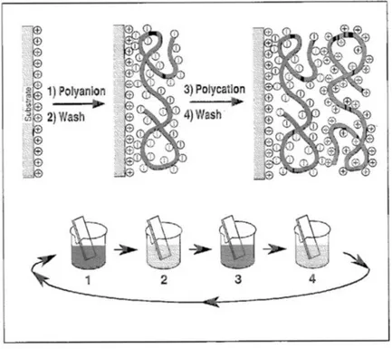
The concept underlying layer-by-layer (LBL) self-assembly techniques utilizing colloidal particles was initially described by Iler in 1966.39 Decher et al. produced the thin film
multilayers by employing the LBL self-assembly technique which employs the electrostatic attraction of oppositely charged materials in aqueous solution.40,41 A
schematic illustration of film deposition via the LBL self-assembly method is depicted in
Figure 1-3.42
The LBL technique is applicable to a wide spectrum of starting reagents, including small organic or inorganic molecules,43 macromolecules,44 biomacromolecules45 and colloids
such as metallic or oxide colloids in addition to latex particles.46-48 The LBL self-assembly
Chapter 1. Introduction of this study
5
multilayer as the LBL deposition involved is extremely simple and environmentally-friendly, enables easy material coating and represents a low-cost approach with no requirement for specific condition such as vacuum or high pressure, or low or high temperatures. Furthermore, the LBL self-assembly technique can regulate surface structure and film thickness with macro- or nano-scale precision. Film thickness is measured by the in-situ deposition of polyelectrolytes or nanoparticles which assemble on the quartz crystal microbalance (QCM) electrode.
Figure 1-3. A schematic depiction of film deposition via the LBL self-assembly technique. Reproduced with permission from Ref. 42.
The resonance of QCM electrodes hinders when the material deposition or detached from the surface of resonator. The Sauerbrey equation, describes how the resonant frequency shift Δƒ, of a QCM is proportional to the mass change Δm, of 1 ng of QCM material:49
6
(1.1)
1.3.2. Electrospinning
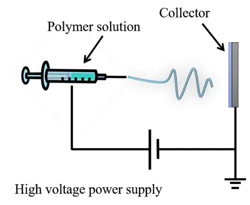
Electrospinning offers a basic general methodology for producing fibers from a wide variety of compounds including polymers, composites and ceramics. There has been great interest in this technique following the first description of the electrospinning approach50
due to the high specific surface area and high porosity of the compounds generated. Furthermore, scans from such electrospun porous nanofibers mimic the micromorphology of the extracellular matrix (ECM) of body tissues, while enhancing cell migration and proliferation. The electrospinning approach has been investigated in different fields. Many researchers have chosen to focus on biomedical applications which utilize nanofiber derived from the electrospinning approach, for example in tissue engineering, drug delivery systems, enzyme immobilization techniques and wound dressing developments.51-53 Previous reports have demonstrated that the electrospun fibers are
appropriate for tissue engineering.54,55 Electrospun fibers possess diameters resembling
the fibrous ECM in the body.56 The electrospinning process is depicted in Figure 1-4.
Electrospun polymeric nanofibers have increased their application in a variety of fields over the past decade, to include applications such as filtration,57 composite materials,58
Chapter 1. Introduction of this study
7
Figure 1-4. Depiction of the electrospinning process.
1.3.3. Surface Wettability
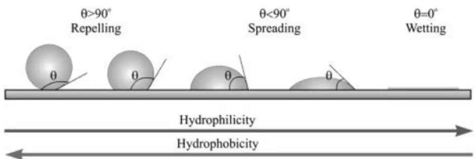
The degree of surface wettability is correlated with the contact angle, which can be defined as the angle between a solid surface and a liquid droplet (see Figure 1-5). A contact angle ranging between 0 - 90° is viewed as a hydrophilic surface on wetting. Conversely, a contact angle value in excess of 90° is viewed as a non-wetting hydrophobic surface. In addition, a superhydrophobic surface is defined by a contact angle greater than 150°. Superhydrophobic surface represent a completely non-wetting surface; whereas a superhydrophilic surface is defined by a contact angle less than 5° which represents a completely wetting surface.
8
Figure 1-5. The surface wettability model of hydrophobic surface and hydrophilic surface. Reproduced with permission from Ref. 62.
1.4. Dissertation overview
Current advancements in biological knowledge are facilitating real-life application of industrial and medical developments. Coating technologies provide simple and inexpensive medical developments for treatment of target areas with promising innovative approaches addressing various medical properties e.g. bio-fouling,63,64
antithrombotic,65,66 antibacterial67,68 and antiadhesion effect,69 etc. This dissertation
examines two examples potentially relevant to our daily life applications. Firstly, the requirement to achieve rapid hemostasis following injury or surgical procedure. Rapid hemostasis following injury or surgery is likely to promote rapid healing, facilitating return to ordinary daily activities. Secondly, medical instruments employed during surgical operations and other medical treatments, frequently experience problems caused by tissue adhesion on their surfaces. In addition, these instruments are used in conjunction with high temperatures, healthy tissues are frequently damaged by contact with the instrument surfaces, with charred tissue being difficult to detach. Anti-adhesion technology for human tissue related problems has the potential to solve these problems.
Chapter 1. Introduction of this study
9
Chapter 1 describes introduction and overview of this dissertation with thesis outline. During medical treatment and following accidental injury in our daily life, rapid hemostasis is the most significant factor for preventing death and promoting rapid wound healing. This thesis seeks to examine the ways in which appropriate and safe nanofiber coatings can be applied to promote rapid hemostasis.
Chapter 2 describes how calcium carbonate composites providing rapid blood coagulability can be utilized within a coating methodology onto a particle surface by employing the LBL self-assembly technique. By controlling the surface structure and coating multilayers, an artificial calcium carbonate composite (possessing faster blood coagulabilitythan pure calcium carbonate and cuttlefish bone alone) was developed.
Chapter 3 describes how utilization of nanofiber increases the surface area available for attachment of calcium carbonate and other natural materials to enhance blood coagulation. This is achieved by utilization of natural materials and modified nanofiber surface wettability (from hydrophobic to hydrophilic with respect to blood contact angle). Specific blood coagulation testing is performed in vivo via employment of a nanofiber mat.
Chapter 4 describes application of anti-adhesion techniques for metallic surfaces in contact with biological surfaces via modification of surface wettability of the metallic surface. Medical treatments frequently encounter significant problems with hemostasis when employing metallic medical devices as a result of tissue adhesion. In this chapter, firstly the problems of adhesion between metallic and biological surfaces are described. To address these problems, a superhydrophobic material was coated onto the metallic surface. The superhydrophobic surface demonstrated good anti-adhesion abilities against the water-constituted biological surface.
10
Chapter 5 describes advancements in film coatings for metallic surfaces to protect against adhesion by oil and water-based compounds. Chapter 4 describes how superhydrophobic surfaces provide good anti-adhesion protection against water-based compounds, such surfaces can only afford weak protection against oil-based media. Oil permeation in the superhydrophobic surface adversely impacts the structure of the superhydrophobic surface. Therefore, the results of investigations into omniphobic surfaces, offering anti-adhesion protection against both oil- and water-based media, are detailed and their effectiveness in solving these problems described.
Chapter 6 summarizes this study, providing conclusions and recommendations for future work.
Chapter 1. Introduction of this study
11
12
1.5. References
(1) Gawk, J. H.; Sohn, S. Y. Identifying the trends in wound-healing patents for successful investment strategies. PloS One2017, 12(3), 1-19.
(2) Arnaud, F.; Parreno-Sadalan, D.; Tomori, T.; Delima, M. G.; Teranishi, K.; Carr, W.; McNamee, G.; McKeague, A.; Govindaraj, K.; Beadling, C.; Lutz, C.; Sharp, T.; Mog, S.; Burris, D.; McCarron, R. Comparison of 10 hemostatic dressings in a groin transection model in swine. J. Trauma2009, 67, 848−855.
(3) Cox, E. D.; Schreiber, M. A.; McManus, J.; Wade, C. E.; Holcomb, J. B. New hemostatic agents in the combat setting. Transfusion2009, 49, 248S−255S.
(4) Kinoshita, T.; Kanehira, E.; Omura, K.; Kawakami, K.; Watanabe, Y. Experimental study on heat production by a 23.5-kHz ultrasonically activated device for endoscopic surgery. Surg. Endosc. 1999, 13, 621-625.
(5) McIntosh, S. Hematologic and oncologic complications in the critically ill child.
Yale J. Biol. Med.1984, 57, 199-242.
(6) Segers, K.; Dahlbäck, B.; Nicolaes, G. A. F. Coagulation factor V and thrombophilia: Background and mechanisms. Thromb Haemost 2007, 98, 530– 542.
(7) Qin, Y. Alginate fibres: an overview of the production processes and applications in wound management. Polym. Int. 2008, 57,171-180.
(8) Hajiali, H.; Heredia-Guerrero, J. A.; Liakos, I.; Athanassiou, A.; Mele, E. Alginate Nanofibrous Mats with Adjustable Degradation Rate for Regenerative Medicine. Biomacromolecules 2015, 16, 936-943.
Chapter 1. Introduction of this study
13
(9) Liang, D.; Lu, Z.; Yang, H.; Gao, J.; Chen, R. Novel Asymmetric Wettable AgNPs/Chitosan Wound Dressing: In Vitro and In Vivo Evaluation. ACS Appl. Mater. Interfaces2016, 8, 3958−3968.
(10) Dowling, M. B.; MacIntire, I. C.; White, J. C.; Narayan, M.; Duggan, M. J.; King, D. R.; Raghavan, S. R. Sprayable Foams Based on an Amphiphilic Biopolymer for Control of Hemorrhage Without Compression. ACS Biomater. Sci. Eng.2015, 1, 440−447.
(11)Malis, L.I. Electrosurgery. Technical note. J. Neurosurg.1996, 85(5), 970-975
(12)Massarweh, N. N.; Cosgriff, N.; Slakey, D. P. Electrosurgery: History, Principles, and Current and Future Uses. J. Am. Coll. Surg. 2006, 202(3), 520–530.
(13) Boughton, R. S.; Spencer, S. K. Electrosurgical fundamentals. J. Am. Acad.
Dermatol. 1987, 16(4), 862-867.
(14) Hainer, B. L. Fundamentals Of Electrosurgery. J. Am. Board. Fam. Med.1991, 4(6), 419-426.
(15) Schemmel, M.; Haefner, H. K.; Selvaggi, S. M.; Warren, J. S.; Termin, C. S.; Hurd, W. W. Comparison of the ultrasonic scalpel to CO2 laser and electrosurgery
in terms of tissue injury and adhesion formation in a rabbit mode. Fertil. Steril.
1997, 67(2), 382–386.
(16) Tayyar, M.; Basbug, M. The effects of intraperitoneal piroxicam and low molecular weight heparin in prevention of adhesion reformation in rat uterine horn. Res. Exp. Med.1999, 198, 269–275.
14
(17) Guvenal, T.; Cetin, A.; Ozdemir, H.; Yanar, O.; Kaya, T. Prevention of post-operative adhesion formation in rat uterine horn model by nimesulide: a selective COX-2 inhibitor. Hum. Reprod.2001, 16, 1732–1735.
(18) Gutmann, J. N.; Diamond, M. P. Principles of laparoscopic microsurgery and adhesion prevention. In Practical Manual of Operative Laparoscopy and Hysteroscopy; Azziz, R., Murphy A. A., Eds.; Springer: New York, 1992; pp 55– 64.
(19) Gutmann, J. N.; Penzias, A. S.; Diamond, M. P. Adhesions in reproductive surgery. In Reproductive Medicine and Surgery; Wallach, E. E., Zaccur, H. A., Eds.; Mosby: St. Louis, 1995; pp 681–693.
(20) Diamond, M. P.; DeCherney, A. H. Pathogenesis of adhesion formation/reformation: Application to reproductive pelvic surgery. Microsurgery
1987, 8(2), 103–108.
(21) Edwards, G. A.; Glattauer, V.; Nash, T. J.; White, J. F.; Brock, K. A.; Werkmeister, J. A.; Ramshaw, J. A. M. In vivo evaluation of a collagenous membrane as an absorbable adhesion barrier. J. Biomed. Mater. Res. 1997, 34, 291–297.
(22) Oh, S. H.; Kang, J. G.; Lee, J. H. Co-micellized Pluronic mixture with thermo-sensitivity and residence stability as an injectable tissue adhesion barrier hydrogel.
J. Biomed. Mater. Res., Part B 2018, 106, 172-182.
(23) Dunn, R.; Lyman, M. D.; Edelman, P. G.; Campbell, P. K.; Evaluation of the SprayGel™ adhesion barrier in the rat cecum abrasion and rabbit uterine horn adhesion models. Fertil. Steril.2001, 75, 411–416.
Chapter 1. Introduction of this study
15
(24) Lauder, C. I. W.; Garcea, G.; Strickland, A.; Maddern, G. J. Abdominal adhesion prevention: still a sticky subject. Dig Surg.2010, 27, 347–358.
(25) Nappi, C.; Sardo, A. D. S.; Greco, E.; Guida, M.; Bettocchi, S.; Bifulco, G. Prevention of adhesions in gynaecological endoscopy. Hum. Reprod. Update
2007, 13, 379–394.
(26) Cheong, Y. C.; Laird, S. M.; Li, T. C.; Shelton, J. B.; Ledger, W. L.; Cooke, I. D. Peritoneal healing and adhesion formation/reformation. Hum. Reprod. Update
2001, 7, 556–566.
(27) Hellebrekers, B. W. J.; Emeis, J. J.; Kooistra, T.; Trimbos J. B.; Moore, N. R.; Zwinderman, K. H.; Trimbos-Kemper, T. C. M. A role for fibrinolytic system in postsurgical adhesion formation. Fertil. Steril.2005, 83, 122–129.
(28) Kobayashi, M.; Toguchida, J.; Oka, M. Development of the shields for tendon injury repair using polyvinyl alcohol — hydrogel (PVA-H). J. Biomed. Mater. Res.
2001, 58(4), 344–351.
(29) Ceviker, N.; Keskil, S.; Baykaner, K. A New Coated Bipolar Coagulator: Technical Note. Acta Neurochir. 1998, 140(6), 619-620.
(30) Kang, S. K.; Kim, P. Y.; Koo, I. G.; Kim, H. Y.; Jung, J. C.; Choi, M. Y.; Lee, J. K.; Collins, G. J. Non-stick Polymer Coatings for Energy-based Surgical Devices Employed in Vessel Sealing. Plasma Process. Polym. 2012, 9(4), 446–452. (31) Young, R. L.; Mason, B. A.; Cota, J.; Wheeler, J. M.; Zund, G. The use of an
amniotic membrane graft to prevent postoperative adhesions. Fertil Steril. 1991, 55(3), 624–628.
16
(32) Matsuda, S.; Se, N.; Iwata, H.; Ikada, Y. Evaluation of the antiadhesion potential of UV cross-linked gelatin films in a rat abdominal model. Biomaterials 2002, 23(14), 2901–2908.
(33) Arnold, P. B.; Green, C. W.; Foresman, P. A.; Rodeheaver, G. T. Evaluation of resorbable barriers for preventing surgical adhesions. Fertil Steril. 2000, 73(1), 157–161.
(34) Donzelli, J.; Leonetti, J. P.; Wurster, R. D.; Lee, J. M.; Young, M. R. I. Neuroprotection Due to Irrigation During Bipolar Cautery. Arch Otolaryngol Head Neck Surg. 2000, 126(2), 149-153.
(35) Sakatani, K.; Ohtaki, M.; Morimoto, S.; Hashi, K. Isotonic mannitol and the prevention of local heat generation and tissue adherence to bipolar diathermy forceps tips during electrical coagulation. J. Neurosurg. 1995, 82(4), 669-671. (36) Mikami, T.; Takahashi, A.; Hashi, K.; Gasa, S.; Houkin, K. Performance of
bipolar forceps during coagulation and its dependence on the tip material: a quantitative experimental assay. J. Neurosurg. 2004, 100(1), 133-138.
(37) Zapp, J. A. Jr; Limperos, G.; Brinker, K. C. Toxicity of pyrolysis products of Teflon®
tetrafluoroethylene resin. Paper presented at the American Industrial Hygiene Association Annual Meeting. 1955.
(38) Magro, B.; Mita, P.; Bracco, G.; Coccia, E.; Scarselli, G. Expanded poly-tetrafluoroethylene surgical membrane in ovarian surgery on the rabbit. Biocompatibility, adhesion prevention properties and ability to preserve reproductive capacity. J. Reprod. Med.1996, 41, 73–78.
(39) Iler, R. K. MULTILAYERS OF COLLOIDAL PARTICLES. J. Colloid Interface. Sci. 1966, 21, 569-594.
Chapter 1. Introduction of this study
17
(40) Decher, G.; Hong, J. D. Germ. Pat. DE 402, 6978, 1990.
(41) Decher, G.; Hong, J. D. Buildup of ultrathin multilayer films by a self-assembly process. 1 Consecutive adsorption of anionic and cationic bipolar amphiphiles on charged surfaces. Macromol. Chem. Macro. Symp. 1991, 46, 321-327.
(42) Decher, G.; Eckle, M.; Schmitt, J.; Struth, B. Layer-by-layer assembled multicomposite films. Curr. Opin. Colloid Interface Sci. 1998, 3, 32-39.
(43) Aremi, K.; Wagner, M. J.; Wrighton, M. S. Layer-by-Layer Growth of Electrostatically Assembled Multilayer Porphyrin Films. Langmuir 1996, 12, 5393-5398.
(44) Lvov, Y.; Decher, G.; Höhwald, H. Assembly, Structural Characterization, and Thermal Behavior of Layer-by-Layer Deposited Ultrathin Films of Poly(vinyl sulfate) and Poly(allylamine). Langmuir 1993, 9, 481-486.
(45) Sun, Y.; Zhang, X.; Sun, C.; Wang, B. Shen, J. Fabrication of ultrathin film containing bienzyme of glucose oxidase and glucoamylase based on electrostatic interaction and its potential application as a maltose sensor. Macromol. Chem. Phys. 1996,197, 147-153.
(46) Keller, S. W.; Kim, H. N.; Mallouk, T. E. Layer-by-Layer Assembly of Intercalation Compounds and Heterostructures on Surfaces: Toward Molecular "Beaker" Epitaxy. J. Am. Chem. Soc.1994, 116, 8817-8818.
(47) Kleinfeld, E. R.; Ferguson, G. S. Stepwise Formation of Multilayered Nanostructural Films from Macromolecular Precursors. Science. 1994, 265, 370-373.
(48) Ferguson, G. S.; Kleinfeld, E. R. Mosaic tiling in molecular dimensions. Adv. Mater. 1995, 7, 414-416.
18
(49) Sauerbrey, G.Z. Use of quartz vibrator for weighing thin films on a
microbalance. Z. Phys.1959, 155, 206
(50) Formhals. A. U.S. Patent 1,975,504, 1934.
(51) Li, W. J.; Laurencin, C. T.; Caterson, E. J.; Tuan, R. S.; Ko, F. K. Electrospun nanofibrous structure: A novel scaffold for tissue engineering. J. Biomed. Mater. Res. 2000, 60, 613-621.
(52) Agarwal, S.; Wendorff, J. H.; Greiner, A. Use of electrospinning technique for biomedical applications. Polymer 2008, 49, 5603–5621.
(53) Katti, D. S.; Robinson, K. W.; Ko, F. K.; Laurencin. C. T. Bioresorbable nanofiber‐based systems for wound healing and drug delivery: Optimization of fabrication parameters. J. Biomed. Mater. Res. B: Appl. Biomater. 2004, 70B(2), 286–296.
(54) Matthews, J. A.; Wnek, G. E.; Simpson, D. G.; Bowlin. G. L. Electrospinning of Collagen Nanofibers. Biomacromolecules2002, 3, 232–238.
(55) Li, W. J.; Laurencin, C. T.; Caterson, E. J.; Tuan, R. S.; Ko. F. K. Electrospun nanofibrous structure: A novel scaffold for tissue engineering J. Biomed. Mater. Res. 2002, 60, 613–621.
(56) Ma, Z.; Kotaki, M.; Inai, R.; Ramakrishna, S. Potential of Nanofiber Matrix as Tissue-Engineering Scaffolds. Tissue Eng. 2005, 11, 101−109.
(57) Deitzel, J. M.; Kosik, W.; McKnight, S. H.; Ten, N. C. B.; Desimone, J. M.; Crette, S. Electrospinning of polymer nanofibers with specific surface chemistry.
Chapter 1. Introduction of this study
19
(58) Drew, C.; Liu, X.; Ziegler, D.; Wang, X.; Bruno, F. F.; Whitten, J.; Samuelson, L. A.; Kumar, J. Metal Oxide-Coated Polymer Nanofibers. Nano Lett. 2003, 3, 143-147.
(59) Yang, F.; Wolke, J. G. C.; Jansen, J. A. Biomimetic calcium phosphate coating on electrospun poly(ɛ-caprolactone) scaffolds for bone tissue engineering. Chem. Eng. J. 2008, 137, 154–161.
(60) Li, W. J.; Danielson, K. G.; Alexander, P. G.; Tuan, R. S. Biological response of chondrocytes cultured in three‐dimensional nanofibrous poly(ϵ‐caprolactone) scaffolds. J. Biomed. Mater. Res. 2003, 67, 1105-1114.
(61) Liu, H.; Kameoka, J.; Czaplewski, D. A.; Craighead, H. G. Polymeric Nanowire Chemical Sensor. Nano Lett. 2004, 4, 671-675.
(62) Krasowska, M.; Zawala, J.; Malysa, K. Air at Hydrophobic Surfaces and Kinetics of Three Phase Contact Formation. Adv. Colloid Interface Sci. 2009, 147–148, 155–169.
(63) Hansson, K. M.; Tosatti, S.; Isaksson, J.; Wetterö, J.; Textor, M.; Lindahl, T. L.; Tengvall, P. Whole blood coagulation on protein adsorption-resistant PEG and peptide functionalised PEG-coated titanium surfaces. Biomaterials 2005, 26(8), 861-872.
(64) Krishnan, S.; Weinmanb C. J.; Ober, C. K. Advances in polymers for anti-biofouling surfaces. J. Mater. Chem. 2008, 18, 3405-3413.
(65) Ragaseema, V. M.; Unnikrishnan, S.; Kalliyana Krishnan, V.; Krishnan, L. K. The antithrombotic and antimicrobial properties of PEG-protected silver nanoparticle coated surfaces. Biomaterials2012, 33(11), 3083-3092.
20
(66) Manabe, K.; Kyung, K. H.; Shiratori, S. Biocompatible slippery fluid-infused films composed of chitosan and alginate via layer-by-layer self-assembly and their antithrombogenicity. ACS Appl. Mater. Interfaces2015, 7, 4763−4771.
(67) Stevens, K. N. J.; Crespo-Biel, O.; van den Bosch, E. E. M.; Dias, A. A.; Knetsch, M. L. W.; Aldenhoff, Y. B. J.; van der Veen, F. H.; Maessen, J. G.; Stobberingh, E. E.; Koole, L. H. The relationship between the antimicrobial effect of catheter coatings containing silver nanoparticles and the coagulation of contacting blood. Biomaterial2009, 30(22), 3682-3690.
(68) Lee, D.; Cohen, R. E.; Rubner, M. F. Antibacterial Properties of Ag Nanoparticle Loaded Multilayers and Formation of Magnetically Directed Antibacterial Microparticles. Langmuir2005, 21(21), 9651-9659.
(69) Faure, E.; Falentin‐Daudré, C.; Lanero, T. S.; Vreuls, C.; Zocchi, G.; Van De Weerdt, C.; Martial, J.; Jérôme, C.; Duwez, A.; Detrembleur, C. Functional Nanogels as Platforms for Imparting Antibacterial, Antibiofilm, and Antiadhesion Activities to Stainless Steel. Adv. Funct. Mater. 2012, 22, 5271-5282.
Chapter 2. Enhancement of Blood Coagulation Calcium Carbonate Composite Mimicking Cuttlefish Bone by Layer-by-Layer Method
21
Chapter 2. Enhancement of Blood Coagulation Calcium
Carbonate Composite Mimicking Cuttlefish Bone by
Layer-by-Layer Method
This chapter is based on [Park, J. Y.; Kyung, K. H.; Kim, S. H.; Shiratori, S.; Fabrication of Blood Coagulability Calcium Carbonate Composite Mimicking Cuttlefish Bone by Layer-by-Layer Method. Science of Advanced Materials 2014, 6(11), 2522-2525.]
2.1. Introduction
Generally, a healthy individual can tolerate losing around 10–15% of their total blood volume without requiring medical assistance.1 However, if blood loss exceeds more than
around a third of the circulating blood total, the individual will be in a serious condition requiring urgent medical treatment.2 Consequently, the challenge of preventing death
must address rapid hemostasis in order to stop blood loss as quickly as possible.3
Calcium carbonate (CaCO3) has been employed in a number of fields, especially biology,
as a source of calcium ions.4,5 In addition, CaCO
3 can enhance tissue regeneration under
acidic conditions6 and can also be metabolized naturally by the human body.7
Biomaterials can either be sourced naturally (such as blood vessels, or proteins such as collagen) or be derived synthetically (such as polymers, metal composites or ceramic) materials). Biomaterials can comprise all, or part of, a living structure or biomedical device. Biopolymers are biocompatible and non-toxic to the human body, biodegradable and environmentally-friendly.8 Biopolymers include polycaprolactone (PCL), polylactic
acid (PLA), polyglycolic acid (PGA), poly(L-lactide-co-glycolide) (PLGA) and alginates which are anionic polysaccharides commonly found in the cell walls of brown seaweed,
22
where they form a linear copolymer with homopoolymeric blocks of (1-4)-linked β-D-mannuronic acid and (1,3)-α-L-guluronic acid.9-13 Bioactive materials are classified according to their activity. Bioactive materials include proteoglycans, collagen, non-collagenous proteins, alginates and chitosan. β-chitosan is formed from the deacetylation of β-chitin, with which it shares a number of similarities.14 As a consequence of their
excellent biocompatibility, β-chitin and β-chitosan have been extensively utilized in the management of wound healing and drug delivery systems.15 Since promotion of wound
healing is correlated with collagenase activity, and since chitosan demonstrates a greater collagenase activity than chitin,16 β-chitosan is correlated with excellent wound healing
capability.17-24 This chapter focusses on the application of CaCO
3 and other helpful
materials for the promotion of blood coagulation. Synthetic CaCO3 was produced from
the reaction of calcium chloride and sodium carbonate. Subsequently, sodium alginate and β-chitosan were alternately coated on a prepared CaCO3 substrate by the
Layer-by-Layer (LBL) self-assembly method. This led to the ability to confirm the blood coagulation efficiency of LBL-coated CaCO3.
2.2. Experimental section
2.2.1. Materials
CaCO3 synthesis utilized the following reagents without the requirement for further
purification: calcium chloride (CaCl2, Junsei Chemical Co., Ltd., Japan; purity = min.
99.5%); sodium carbonate (Na2CO3, Junsei Chemical co., Ltd. Japan; purity = min.
99.5%); sodium dodecyl sulfate (SDS, Junsei Chemical Co., Ltd., Japan); poly (sodium 4-sytrene-sulfonate) (PSS, Sigma-Aldrich, St. Louis, MO, USA; MW = 70,000); acetic acid (Kanto Chemical Co., Inc., Malaysia; purity = min. 99.7 %). For CaCO3 composite
Chapter 2. Enhancement of Blood Coagulation Calcium Carbonate Composite Mimicking Cuttlefish Bone by Layer-by-Layer Method
23
generation, β-chitosan (Arabio Co., Ltd., Korea; average MW = 180 K) and sodium alginate (Nacalai tesque. Japan) were utilized again with no additional purification. Highly purified water was acquired by deionization and filtration (resistivity > 18.2 MΩ∙cm). Cuttlefish bone was acquired from Hanyaknara, Korea.
2.2.2. Synthesis of calcium carbonate
CaCO3 was synthesized by combining a number of materials. Firstly, as outlined in the
standard experimental procedure,25 100 mL of aqueous 0.2 M CaCl
2 were added to an
aqueous solution of 0.2 M Na2CO3, stirred vigorously for 5 min. The solution was then
permitted to rest for 24 h at room temperature. The resulting precipitate was subsequently rinsed 3 times with distilled water and dried at 60 °C prior to harvesting CaCO3.
Secondly, 100 ml of aqueous 0.2 M CaCl2 were added to aqueous 0.2 M Na2CO3 in the
presence of PSS (4 g/L) and SDS (0.1 wt%) and stirred vigorously for 5 min. The same experimental procedure as outline above was then performed.
2.2.3. Production of calcium carbonate composite
The harvested calcium carbonate was subsequently coated with β-chitosan and sodium alginate via LBL self-assembly method using a centrifugal separator. β-chitosan was dissolved in water and the pH adjusted to pH 4.0 by addition of acetic acid. The pH of the aqueous sodium alginate solution was not altered. The harvested calcium carbonate was added to the aqueous sodium alginate solution for 3 min and then centrifuged at 1000 rpm for 1 min. The residue was washed three times for 1 min with distilled water. The cleaned residue was then centrifuged at 1000 rpm for 1 min. The washing process was repeated, and the collected product was added to aqueous β-chitosan solution for 3 min. The product
24
was then centrifuged at 1000 rpm for 1 min rinsed 3 times with distilled water for 1 min, as previously. These process operations represent 1 cycle. Multiple cycles were conducted to obtain the required multilayer calcium carbonate composite. The final product was dried at 60 °C to give the final calcium carbonate composite product.
2.2.4. Measurement of layer thickness and coating material quantity
Layer thickness was measured via Auto-Elipsometry (Five-lab, Mary-102). The in-situ
deposition of polyelectrolytes or nanoparticles onto the electrode of quartz crystal microbalance (QCM)26 was monitored. Multilayer samples (β-chitosan and sodium
alginate) were produced with glass and QCM (AT-cut, 10 MHz) employed for measurement. The glass and QCM substrates were agitated ultrasonically in KOH solution (1.0 wt%), mixed with distilled water and ethanol (2:3 in v/v) for 5 min, and subsequently washed using distilled water. This method was used to produce negatively charged substrates. The substrate was subsequently alternately dipped into β-chitosan and sodium alginate solutions. Each sample was produced by identical experimental methodologies.
2.2.5. Whole-blood-clotting studies
Blood-clotting investigations were conducted according to methods described in published literature.27,28 Pig blood was utilized for blood coagulation testing and placed
in a 2 ml bottle. 0.01g of composite calcium carbonate and 0.1 ml of pig blood were added to each sample and the mixtures incubated at 37 °C for 3 min, prior to drying at room temperature for 10 min. The samples were subsequently washed in 50 ml of distilled water
Chapter 2. Enhancement of Blood Coagulation Calcium Carbonate Composite Mimicking Cuttlefish Bone by Layer-by-Layer Method
25
whilst subject to stirring at 250 rpm for 15 s. 1.5 ml of solution were extracted from the 2 ml bottle and centrifuged at 1000 rpm for 1 min and the supernatant collected. The optical density (OD) of the supernatant was measured by ultraviolet visible (UV-vis) spectrophotometer (Shimadzu UV mini-1240) at 540 nm.
2.3. Results and discussion
2.3.1. Morphologies of calcium carbonate and calcium carbonate composite
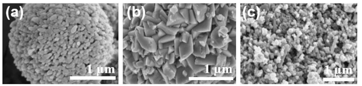
The surface structure of natural cuttlefish bone is difficult to control. Therefore, to attempt these two alternative morphologies of CaCO3 were prepared using SDS. Comparisons of
CaCO3 and cuttlefish bone morphologies were observed via a field emission scanning
electron microscope (FE-SEM, Hitachi, S-4700). Figure 2-1 illustrates the SEM images obtained comparing CaCO3 and cuttlefishbone. The surface structure of CaCO3 without
SDS is spherical (Figure. 2-1a). CaCO3 with SDS is more squamous (Figure 2-1b), with
the surface structure of cuttlefish bone resembling vaterite CaCO3 (Figure 2-1c). The
surface structure of CaCO3 synthesized with SDS clearly differs from that of CaCO3
without SDS and cuttlefish bone.
Figure 2-1. SEM images: (a) CaCO3 without SDS, (b)CaCO3 with SDS (c) Cuttlefish
26 2.3.2. Analyzing crystal structure
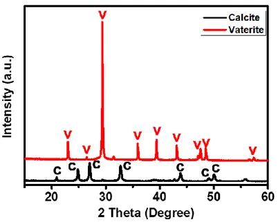
CaCO3 exists as three varieties of anhydrous polymorphs: calcite, aragonite and vaterite.29
Most calcite CaCO3 crystals are rhombohedric; aragonite CaCO3 has a needle-like shape;
and vaterite CaCO3 is spherical.30 Calcite represents the most thermodynamically stable
form of CaCO3 at room temperature and ambient pressure conditions; vaterite is unstable
under these conditions. The prepared samples were observed by X-ray diffraction (XRD) using an X-ray diffractometer (D8 advance, Bruker). CaCO3 with SDS resembles a calcite
phase crystal structure, as depicted in Figure 2-2. CaCO3 without SDS resembles a
vaterite phase crystal structure. It is thought that SDS polar groups provide active sites for CaCO3 nucleation as a consequence of their electrostatic interaction with calcium
ions.31 In addition, the surfactant concentration was also observed to alter the sample
surface structure.
Chapter 2. Enhancement of Blood Coagulation Calcium Carbonate Composite Mimicking Cuttlefish Bone by Layer-by-Layer Method
27
2.3.3. Coating CaCO3 by the Layer-by-Layer (LBL) self-assembly method.
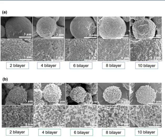
Both CaCO3 without SDS and CaCO3 with SDS were coated via the LBL self-assembly
method. The layer structure lends itself to reveal each material feature in one composite. When used to apply surface coatings, the LBL method can generate samples with careful regulation of coating morphology and thickness within the nanoscale range, whilst also providing good overall levels of substrate uniformity. In addition, the LBL method can regulate the quantity of coating material applied. Two varieties of CaCO3 exist: a
biogenically-derived form and a synthetically-derived form. In aqueous solution, the biogenic form possesses an anionic (negative) charge, whereas the synthetic form possesses a cationic (positive) charge.32 Sodium alginate is an anionically-charged
aqueous solution, whereas β-chitosan is a cationically-charged aqueous solution.33 Acting
as the substrate, CaCO3 was firstly dipped into sodium alginate solution and then the
coated alginate CaCO3 was subsequently dipped into β-chitosan aqueous solution.
Depending upon the electrostatic forces existing between oppositely charged materials, sodium alginate and β-chitosan were alternately coated onto the CaCO3 substrate. The
composite CaCO3 was fabricated to comprise between 0 bilayer to 10 bilayers (see Figure
2-3 which depicts CaCO3 composite varying between 2 bilayers to 10 bilayers). Despite
increasing numbers of bilayers, a clear distinction between CaCO3 surfaces is always
observed. The CaCO3 composite surface is smoother than the non-coated CaCO3
counterpart, indicating that sodium alginate and β-chitosan are contained within the original CaCO3.
28
Figure 2-3. CaCO3 compositewith β-chitosan and sodium alginate fabricated by LBL
method from 2 bilayers to 10 bilayers. (a) Vaterite CaCO3, (b) calcite CaCO3.
2.3.4. Results of layer thickness measurements and coating material quantities
Layer thickness and coating material quantities were measured. It was confirmed that the layer thickness had a propensity to increase with increasing numbers of bilayers. A 10-bilayer sample gave a thickness of around 73.3 nm. Frequency shifts measured using QCM showed increases from 30 to 480 Hz with increasing numbers of bilayers, as depicted in Figure 2-4. In this figure, black square dots represent the quantities of adsorbed β-chitosan. The red circle dots represent the quantities of adsorbed alginate. The Sauerbrey equation,34 confirms a mean of 60.4 ng of β-chitosan and alginate are adsorbed on each bilayer.
Chapter 2. Enhancement of Blood Coagulation Calcium Carbonate Composite Mimicking Cuttlefish Bone by Layer-by-Layer Method
29
Figure 2-4. QCM frequency shift of β-chitosan and alginate.
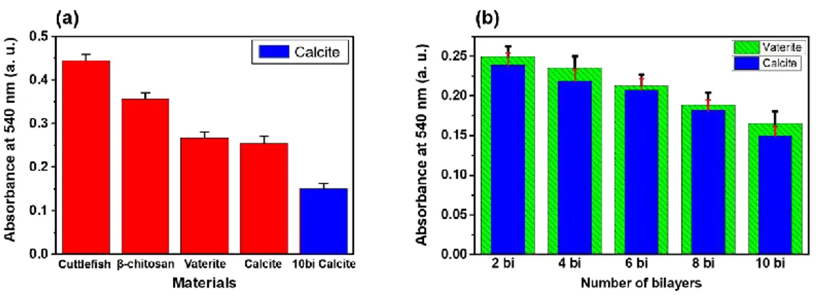
2.3.5. Results from whole-blood-clotting studies
It was confirmed that calcite CaCO3 exhibits the fastest clotting rate compared with other
samples. In Figure 2-5a and b, the lowest absorbance at 540 nm is representative of a faster clotting rate. Figure 2-5a shows that Calcite CaCO3 has fastest clotting rate.
Comparisons of β-chitosan and synthesized CaCO3 indicate that the latterhas a greater
impact on blood coagulability, as the synthesized CaCO3 contains calcium ions, whereas
β-chitosan does not. In addition, comparisons of cuttlefish bone and β-chitosan indicate that the latter has a greater impact on blood coagulation, as the chitosan influences red blood cell aggregation by electrostatic interactions. Although it is accepted that cuttlefish bone contains some β-chitin, the quantities are very low. Figure 2-5b illustrates blood
30
coagulability of CaCO3 composite. It can be seen that increasing number of bilayers
improves the clotting rate, indicating that adsorption increases with increasing β-chitosan and alginate leading to increased blood coagulability of CaCO3 composite. These results
demonstrate an enhanced hemostatic effect permitting faster blood clotting by coating with β-chitosan and alginate. Comparisons of vaterite CaCO3 and calcite CaCO3, indicate
that calcite CaCO3 exhibits a faster clotting rate than vaterite CaCO3. This is possibly
influenced by the fact that in aqueous solution, vaterite easily undergoes phase transition to the more thermodynamically stable calcite phase, as phase transition hinders adsorption of β-chitosan and alginate on the CaCO3 substrate. This effectiveness also tends to
increase with increasing numbers of bilayers.
Figure 2-5. Results of whole-blood clotting studies using pig blood. (a) Comparison of various materials. (b) Comparison of different CaCO3 surface structures with
increasing bilayers.
2.4 Conclusions
CaCO3 composite for blood coagulation were fabricated via the LBL self-assembly
Chapter 2. Enhancement of Blood Coagulation Calcium Carbonate Composite Mimicking Cuttlefish Bone by Layer-by-Layer Method
31
SEM, UV-vis spectrophotometer and blood clotting studies demonstrated that the CaCO3
composite possesses better blood clotting action than either cuttlefish bone or β-chitosan alone. Consequently, CaCO3 composite can be seen to possess potential for medical
applications. In order to increase the specific surface area available for coatings, the next chapter will address identification of appropriate nanofibers for achieving the overall objective of rapid blood coagulation.
2.5. References
(1) Stewart, R. M.; Myers, J. G.; Dent, D. L.; Ermis, P.; Gray, G. A.; Villarreal, R.; Blow, O.; Woods, B.; McFarland, M.; Garavaglia, J.; Root, H. D.; Pruitt, B. A. Seven hundred fifty-three consecutive deaths in a level I trauma center: The argument for injury prevention. J. Trauma2003, 54, 66−70.
(2) MacLeod, J. B. A.; Lynn, M.; McKenney, M. G.; Cohn, S. M.; Murtha, M. Early coagulopathy predicts mortality in trauma. J. Trauma2003, 55, 39−44.
(3) Kauvar, D. S.; Lefering, R.; Wade, C. E. Impact of hemorrhage on trauma outcome: An overview of epidemiology, clinical presentations, and therapeutic considerations. J. Trauma2006, 60, S3−S9.
(4) Zhang, Y.; Wu, Z.; Shu, Y.; Wang, F.; Cao, W.; Li, W. A novel bioactive vaterite-containing tricalcium silicate bone cement by self hydration synthesis and its biological properties. Mater. Sci. Eng. C. 2017, 79, 23–29.
(5) Trushina, D. B.; Bukreeva, T. V.; Kovalchuk, M. V.; Antipina, M. N. CaCO3 vaterite
microparticles for biomedical and personal care applications. Mater. Sci. Eng. C. 2014,
32
(6) Ma, M. G.; Zhu, J. F. Recent Progress on Fabrication of Calcium-Based Inorganic Biodegradable Nanomaterials. Recent Pat. Nanotechnol.2010, 4, 164–170.
(7) Ohgushi, H.; Okumura, M.; Yoshikawa, T.; Inboue, K.; Senpuku, N.; Tamai, S.; Shors, E. C. Bone formation processin porous calcium carbonate and hydroxyapatite. J. Biomed. Mater. Res.1992, 26(7), 885–895.
(8) Mohanty, A. K.; Misra, M.; Hinrichsen, G. Biofibres, biodegradable polymers and biocomposites: An overview. Macromol. Mater. Eng.2000, 276/277, 1–24.
(9) Cottrell, I. W.; Kovacs, P. Handbook of Water-Soluble Gums and Resins: Alginates;McGraw-Hill: New York, 1980, 2.1.
(10)Whistler, R. L.; Bemiller. J. N. Industrial Gums Polysaccharides and Their Derivatives;Academic Press: San Diego, 1993.
(11)Glicksman, M. Food Science and Technology, Gum Technologyin the Food Industry,Academic Press: New York, 1969. 239.
(12)Mark, H. F.; McKetta, J.; Othmer, D. F. Encyclopedia of Chemical Technology, Seaweed Colloids; Wiley: New York, 1963, 17, 763.
(13)Imeson, A. Thickening and Gelling Agent for Food, Chapter 2: Alginates, Blackie: London,New York, 1997, 23.
(14)Pillai, C.; Paul, W.; Sharma, C. P. Chitin and chitosan polymers: Chemistry, solubility and fiber formation. Prog. Polym. Sci.2009, 34, 641–678.
(15)Aranaz, I.; Mengibar, M.; Harris, R.; Panos, I.; Miralles, B.; Acosta, N.; Galed, G.; Heras, A. Functional Characterization of Chitin and Chitosan. Curr. Chem. Bio.2009, 3 203-230.
Chapter 2. Enhancement of Blood Coagulation Calcium Carbonate Composite Mimicking Cuttlefish Bone by Layer-by-Layer Method
33
(16)Minagawa, T.; Okamura, Y.; Shigemasa, Y.; Minami S.; Okamoto, Y. Effects of molecular weight and deacetylation degree of chitin/chitosan on wound healing.
Carbohydr. Polym.2007, 67. 640-644.
(17)Paul, W.; Sharma, C. P. Chitosan and Alginate Wound Dressings: A Short Review.
Trends Biomater. Artif. Organs.2004, 18, 18-23.
(18)Ueno, H.; Yamada, H.; Tanaka, I.; Kaba, N.; Matsuura, M.; Okumura, M.; Kadosawa, T.; Fujinaga, T. Accelerating effects of chitosan for healing at early phase of experimental open wound in dogs. Biomaterials1999, 20, 1407–1414.
(19)Mi, F. L.; Shyu, S. S.; Wu, Y. B.; Lee, S. T.; Shyong, J. Y.; Huang, R. N. Fabrication and characterization of a sponge-like asymmetric chitosan membrane as a wound dressing. Biomaterials2001, 22, 165–173.
(20)Burkatovskaya, M.; Castano, A. P.; Demidova-Rice, T. N.; Tegos, G. P.; Hamblin, M. R. Effect of chitosan acetate bandage on wound healing in infected and noninfected wounds in mice. Wound Repair Regen.2008, 16, 425–431.
(21)Jin, Y.; Ling, P. X.; He, Y. L.; Zhang, T. M. Five-year review of infections in a burn intensive care unit: High incidence of Acinetobacter baumannii in a tropical climate.
Burns2007, 33, 1027–1031.
(22)Alsarra,I. A.; Chitosan topical gel formulation in the management of burn wounds.
Int. J. Biol. Macromol.2009, 45, 16–21.
(23)Ribeiro, M. P.; Espiga, A.; Silva, D.; Baptista, P.; Henriques, J.; Ferreira, C.; Silva, J. C.; Borges, J. P.; Pires, E.; Chaves, P.; Correia, I. J. Development of a new chitosan hydrogel for wound dressing. Wound Repair Regen.2009, 17, 817–824.
(24)Boucard, N.; Viton, C.; Agay, D.; Mari, E.; Roger, T.; Chancerelle, Y.; Domard, A. The use of physical hydrogels of chitosan for skin regeneration following third-degree