Design for Change: Patterns and Components
for Flexible UI Development
Daniel Sinnig1,2, Homa Javahery2, Jovan Strika3, Peter Forbrig1 and Ahmed Seffah2
(1) Software Engineering Group
The paper studies relations between patterns and components for user-interface design. It demonstrates how components can be considered as implementations of patterns. It also discusses the support of patterns for reverse- and reengineering of existing software. This can especially support the transfer of software to new platforms and devices.
Introduction
Software applications, in general, have become more and more complex. User interfaces are no exception to this rule, and current trends in user interface (UI) design are rapidly evolving. The web, as a vital medium for information transfer, has had an impact on UI design. Although software application logic development has become increasingly driven by engineering techniques and principles, the development of the UI has remained “ad-hoc” and thus has resulted – from a software engineering point of view – in applications of poor architectural quality, causing tremendous costs for maintenance and further evolution [Gaedke et al. 00]. Writing code from scratch is no longer a viable solution. The lack of standards and the broad diversity of technologies have led to the fact that no efficient concept for reuse of solutions and designs has been established yet.
To support systematic UI development, a process incorporating a disciplined form of reuse is needed. The lack of methods in UI development motivated us to explore the combination of components and patterns as core constituents for a novel reuse approach. Patterns help in the reuse of well-known and proven design solutions, and play a significant role throughout the whole UI development process. Components embody reusable solutions at the implementation level.
Core constituents: Patterns and Components
A software component can be defined as a unit of composition with a clearly defined interface, enabling independent deployment and third-party reuse. As a result, it enables practical reuse across multiple applications [Szyperski 98]. Components are a suitable means to implement patterns on a particular platform [Sinnig 04]. Once an appropriate pattern has been chosen and instantiated, a suitable component can be picked to implement the particular pattern instance. In the same way as patterns, components can also be customized and adapted to different contexts of use. Patterns, in general, are of rather conceptual nature and abstract from concrete implementation language independent issues. This generic nature of patterns allows the designer to think “outside” the toolkit at hand [Tidwell 04]. When it comes down to the implementation, the previously conceptually designed aspects for the application must be carried out using a particular programming environment and framework.
In the following we will suggest a UI development process, which incorporates both patterns and components. It will be shown that due to these two core constituents, the process is highly flexible and adaptable. Furthermore, such an integrated approach of using patterns with software components can be a practical step in bridging the conceptual gap that currently exists between the domains of Software Engineering and Human-Computer Interaction; where patterns act as the conceptual design solution used by HCI practitioners and components are the concrete realization and implementation of such design solutions, produced and used by Software Engineers.
The Pattern and Component – Based UI Development Process
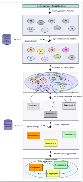
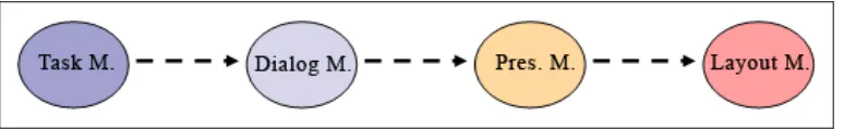
The Pattern and Component-Based (PCB) process allows for flexible and systematic UI development, by unifying pattern and component-based methodologies into one systematic process. As portrayed in Figure 1 the process consists of six logical and mutually successive steps going from the conceptual to implementation level.
Step 1: Pattern Selection.
The PCB process begins after the analysis phase and the requirements specification. It is assumed that the problem domain has already been precisely specified. A set of appropriate patterns is selected to tackle different design aspects of the UI. Patterns are problem oriented, proposing a solution to a problem, which is applicable in a certain context of use. As demonstrated in chapter 2 different kinds of UI patterns (task, dialog, presentation and layout) exist for tackling different aspects of the UI. Choosing appropriate patterns correctly depends strongly on the experience and the creativity of the designer; these selected patterns will shape the basic nature of the future UI.
Step 2: Pattern Instantiation.
A pattern is an abstraction that must be instantiated.Before the pattern solution stated in the pattern is really tangible and applicable, it must be adapted to the current context of use. The second step of the PCB process consists of adjusting the patterns of step 1 according to the context of use resulting in a set of pattern instances.
At this point it is noteworthy that there is no universal accepted definition of “context”. Researchers from different fields have given their own definitions of context. For instance, Shilit and Theimer defined context as the location, the identities of people around, and the equipment nearby [Shilit et al. 93]. Schmidt defined the context as the user’s social and physical environments, as well as the task being performed [Schmidt et al. 99].
on conceptualities such as the target user groups, target devices or environmental factors. This pattern adaptation phase can be seen as a first “basic” tuning of the further application, without being specific about the implementation and/or the programming language.
Step 3: Model Construction.
In this step the various patterns instances are associated to different declarative UI models. In particular as described in chapter 2 the pattern instances are used as building blocks to form the various models; these models contain declarative descriptions of the UI facets. If necessary, other artifacts and information may be consulted as well to form the models. For example, personae and archetypes help in the creation of a user task model. Many facets exist as well as related models: Task, domain, user, device, platform, application, presentation, dialogue, navigation, etc. [Vanderdonckt et al. 03]. For the sake of simplicity, Figure 1 shows only the User-Task, the Navigation, the Presentation and the Layout model. We summarize the models, which are related to the user interface under the term UI Multi-Model. [Vanderdonckt et al. 03].
Step 4: Component Selection.
Until now, the user interface is viewed and defined by the UI Multi-Model at a conceptual level. The remaining steps of the process, however, are concerned with the concrete implementation issues of the user interface. Therefore, components are picked in order to implement the UI according to the UI Multi-Model. In particular, since the models are mainly formed and established by patterns, components to implement the various patterns are chosen. If such a component does not exist, it must be developed and implemented. At this point it is to be noted that one component may serve as an implementation for several related patterns.
Step 5: Component Adaptation.
The various components are adapted to the context of use in order to meet two different goals: (1) To insure that the components match the proposed design solutions contained within the UI Multi-Model and described by the pattern instances, and (2) To address issues that have not been considered during the phase of pattern adaptation, such as platform and programming language dependencies. This phase can be seen as a “fine tuning” of the later user interface.
Step 6: Application Assembling.
The adapted components are inter-linked with each other and are used to assemble the UI of the host application.
In the next section we will show that artifacts that have been developed according to PCB process are particularly likely to be reused. We will demonstrate that UIs that are developed according to the process are easy to adapt to new context requirements and that a migration of the UI to a new platform can be undertaken without starting from the scratch.
Case Study: IP-Phone Management Application
We will illustrate an example of a study on developing the UI of a web application for selling and managing IP-Phone service using the PCB process. In the first step of the PCB process, a set of appropriate patterns is selected and mapped to the requirements (see Figure 2).
Figure 2: Requirements, Patterns, and Pattern Instances
In the second step, selected patterns are instantiated to the context of use in order to be reused as building blocks for the models in Step 3. We can illustrate this with the Multi-value Input Form Pattern [Paternò 00],[Sinnig 04], which provides a task structure for entering several values into an input form. In order to apply the pattern to our application, it must be adapted to the particular input fields that should be provided by the form: (1) Registration and editing personal information, and (2) Modifying package features (see Figure 3).
Figure 3: Instance of Multi-value Input Form Pattern
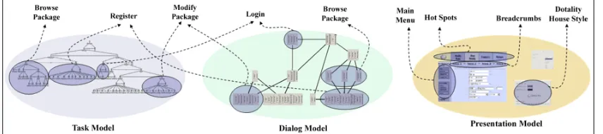
In the third step, the created pattern instances are used as building blocks to form various UI models: The user task model, dialog model and presentation model (see Figure WW). It can be seen that even though the amount of UI patterns is constantly growing, there will always be requirements that are too specific and will not be covered by any pattern. In such a case, other artifacts and information need to be consulted to complete the models.
Figure 4: Models and related Patterns
Table 1: Components Used
Name Brief Description Impl. Patterns
E-Form The E-Form generates and groups a set of input interaction elements.
Multi-value Input Form, Unambiguous Format, Login Navigator The Navigator implements three different types
of navigation aids: (1) Main menu, (2) Hot Spots and (3) Breadcrumbs.
Main Navigation, Quick Access, Breadcrumbs
Tabler The Tabler displays dynamically retrieved or generated information using a table grid.
Browse
In the fifth step, the components are adapted to the context of use, including requirements of our application and technological constraints. For the sake of the IP-Phone Management application, all three selected components generate the UI code based on an XML specification. CSS (stylesheets) were used to determine the layout and style of the rendered UI. Figure TT displays a subset of the XML specification used to adapt the E-form component to serve as a Login Dialog.
Figure 5: Model and Screenshot of E-Form component for Login dialog
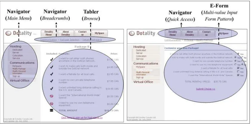
In the final step, the adapted components are inter-linked with each other and are used to assemble the UI of the host application. Since we are using ASP.NET technology, the adapted components are embedded into ASP pages. In addition, other UI elements such as labels, descriptions and images are added to the pages and interlinked with the components.
Figure 6 shows a screenshot of the “Modify Package” ASP page of the IPPhone Management application. The page embeds four different instances of the previously introduced components:
• The Navigator adapted as Main Menu (left), • The Navigator adapted as Hot Spots (top), • The Navigator adapted as Breadcrumbs and
• The E-Form adapted as an Input form for customizing the IPPhone package (center)
UI Reengineering
Systems inevitably change over time. Original requirements have to be modified to account for changing user needs and advances in technology. User interfaces are no exception to this rule, and current trends in user interface (UI) design are rapidly evolving. The web, as a vital medium for information transfer, has had an impact on UI design. Furthermore, the introduction of new platforms and devices, in particular mobile phones and PDAs, has added an extra layer of complication to UI system changes. In the migration of interactive systems to new platforms and architectures, many modifications have to be made to the UI.
Tools are needed to support UI reengineering. Writing code from scratch is no longer a viable solution, and many techniques concentrate on reuse. The lack of methods in UI reengineering motivated us to explore the combination of components and patterns as a reengineering tool. On one hand the use of patterns helps in the reuse of well-known and proven design solutions, and plays a significant role throughout the whole UI reengineering process. On the other hand components embody reusable solutions for the implementation level.
Patterns are an interesting reengineering tool because the same pattern can be instantiated differently on various platforms, such as a Web browser and a Personal Digital Assistant (PDA). For example, the Quick Access pattern helps the user to reach the most commonly used pages quickly from any location in the interface. It can provide direct access to frequently used pages such as What’s New, Search, Contact Us, Home Page, and Site Map. For the purpose of this chapter, we define the Quick Access pattern as a pattern for web environments. However, other application domains are also possible. For a PDA, the Quick Access pattern can be implemented as a combo box using the Wireless Markup Language (WML). For a Web browser, it is implemented as a toolbar using embedded scripts or a Java applet in HTML. Pattern descriptions should provide advice to pattern users for deriving the most suitable instantiation for a given context.
In order to re-adapt the user interface of an application to different requirements, platforms or contexts of use, most of the user interface code has to be modified. UI reengineering techniques can facilitate such a transition. According to Chikofsky [Chikofsky et. al. 90] reengineering is “the examination and alteration of a subject system to reconstitute it in a new form and the subsequent implementation of the new form. In general UI reengineering consists of a reverse engineering phase, a transformation phase, and a forward engineering phase.
• In reverse engineering, the challenge is to understand the interface code for abstracting high-level UI design representations are summarized in the UI Multi Model.
• Forward engineering is the process of generating and implementing the user interface from high-level models.
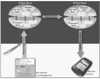
Figure 7 portrays the essence of the UI reengineering process in which the original UI is abstracted into a UI Multi-Model. The UI Multi Model is then transformed and modified in order to meet the new requirements. Eventually the new UI Multi-Model serves as a basis for the re-implementation of the new UI.
Figure 7: Three Phases of UI Re-Engineering
In what follows we will define in greater detail each phase of the general UI reengineering process. In addition we will describe how to readapt respectively retarget a UI using the PCB process.
Reverse Engineering
Chikofsky [Chikofsky et. al. 90] defines reverse engineering as the process of analyzing a subject system to:
“identify the system’s components and their interrelationships, and create representations of the system in another form or at a higher level of abstraction.”
Reverse Engineering is the process of analyzing software code with the objective of recovering its design and specification. In the reverse engineering of the UI of interactive systems, the ideal behavioral specification of the system is an abstract UI model with enough detail to allow appropriate user interface techniques, in particular model-based approaches, to be chosen in the new interface domain [Moore 1996].
All these different facets of the UI are abstracted in to the various high level UI models, which in turn constitute the UI Multi-Model.
Transformation
Transformation is a change to design characteristics. Possible changes include restructuring design architecture, altering a system’s data model or changes to accommodate new requirements. Requirement changes include the addition of new requirements, or the deletion or alteration of existing requirements [Program-Transformation.Org 2004].
For the scope of this thesis the transformation phase consists of redesigning the UI Multi-Model according to the new context of use, such as to accommodate new platform constraints and user needs. The transformation process tries to first identify the problems of the old UI Multi-Model, obtained during reverse engineering, and then attempts to come up with viable solutions that can help create a new UI Multi-Model. The goal of the transformation process is to change the UI Multi-Model in order to meet the new requirements. It is important to note that in the new UI Multi-Model, some of the components of the old model may be reused.
Forward Engineering
Chikowsky defines forward engineering as the “traditional process of moving from high-level abstractions and logical, implementation-independent designs to the physical implementation of the interface.” [Chikofsky and Cross 1990] This last step of UI re-engineering results in the generation of a new UI. This new interface must provide all required services and tasks to the user, and must convey all information exchanged between the user and the system. Several factors must be satisfied during forward engineering, which are indicative of the success of the UI reengineering process [Moore 1994]:
• The new UI has to be consistent with the reengineered UI, in particular in terms of functionality. We are not referring to exact functionality, but rather that the new UI should contain all original functionality even if enhancements or changes are made. • The forward engineering phase should start where the transformation phase left off. In
other words, the new UI abstract model should allow for forward engineering.
• Certain relationships exist between user interface components and pieces of code. It is important to ensure the preservation of these relationships.
Until now, we were looking at the UI re-engineering process from a rather theoretical point of view. In what follows I will describe from a practical point of view how to reengineer a UI, which has been developed according to the PCB process. First I will outline how to re-adapt a UI to new requirements, without changing its target platform (UI adaptation). Second I will show the process of retargeting or migrating a UI to different platforms (UI migration).
UI Adaptation
This section will describe the process of UI adaptation to new requirements without changing its target platform. It is assumed that the UI has been developed according to the PCB process. Generally the adaptation of a User Interface can be distinguished into two cases:
On one hand, the UI is solely changed and adapted at a very low level. Only language and implementation related aspects such as bug fixing or platform specifics layouts (i.e. changing the Look and Feel of Java applications from Metal to Motif [SWING 2002] are tackled. No
“Fine tuning” level (see Figure 1). It is merely necessary to re-adapt the various components of the host application. Reengineering, as defined in the previous section, is not necessary. In this case the used patterns, the UI Multi-Model and the deployed components can be reused. On the other hand, the UI is reengineered as a cause of changed requirements. In this case the UI needs to be reverse engineered in order to abstract the UI Multi-Model and to identify the patterns used to design the interface.
The PCB process explicitly defines connections between its steps, which are helpful for tracing back the UI development (reverse engineering). As portrayed in Figure 1, the outcome of one step is used as input for the next step of the PCB process. Thus, it is easy to grasp the conceptualities of the UI by simply retracing the connections between the UI artifacts defined during the various steps of the PCB process.
Typical UI re-engineering examples are (among others): Changes of the navigational structure (i.e. separate navigation for novice and expert users), re-structuring or re-introduction of UI elements and the introduction of new functions that should be supported by the UI. In each case the UI needs to be reverse engineered.
UI reengineering starts with reverse engineering the implementation of the UI until the pattern level. Each used pattern is then analysed to determine its suitability to the new context of use. Even though it is likely that most of the already used patterns are eligible for reuse, some modifications may require that certain patterns are added, replaced or removed from the UI design. For example the support of new functionality may trigger the incorporation of a new task pattern.
Next, according to the second step of the PCB process, the pattern set is re-instantiated according to the new requirements. As a result the new set of pattern instances will be used to re-create the UI Multi-Model. It is to be noted that only the models, which are affected by the modification at the pattern level and their dependent models are recreated. The remaining models remain unchanged.
Different models have different levels of abstraction. Early stages of software engineering of the user interface focus on general, implementation-independent concepts, which are described at a rather high level or with more abstract models. Later stages of software engineering emphasize implementation details using low-level or less abstract models. Low-level models must take into account platform-specific attributes, whereas high-Low-level models are rather platform independent. Changes made at the conceptual modeling stage (high-level model) will affect all lower levels [Chikofsky et. al. 90].
According to the definition of the task, dialog, presentation and layout model (see chapter 2), the following inter-model dependencies exist:
• The dialog model depends on the task model: Structural and temporal relations between tasks are reused to design the dialog graph.
• The presentation model depends on dialog model: Dialog views and dialog tasks are associated with abstract interaction elements.
• The Layout model depends on presentation model: Concrete style attributes are attached to the abstract interaction elements.
pattern (such as a task pattern) may affect the usage of one or several lower level patterns (i.e. dialog, presentation and layout patterns)
Figure 8: Inter-Model Dependencies
At this point it is noteworthy that that different frameworks (JANUS [Balzert 1996], AME [Märtin 96], MOBI-D [MOBI-D 99], TERESA [TERESA 04]) may have different model definitions and thus different inter-model dependencies.
After re-establishing the UI Multi-Model the previously chosen components are re-evaluated according to their suitability to implement the “new” design. If necessary, new components may be selected or existing components, which are not appropriate anymore, are dismissed.
Before re-deployment each components needs to be customized in order to match the design proposed by the various patterns and captured by the UI Multi-Model. Finally the re-adapted the UI is re-assembled.
Altogether the following artifacts may be reused during UI adaptation:
• Appropriate patterns, which remain applicable in the new context of use
• A sub-set of the UI Multi-Model which does not directly or indirectly depend on the modification of the pattern set
• Components, which are re-deployed to implement the new UI Multi-Model
UI Migration
UI Migration is the process of retargeting the UI from one source-computing platform to another target-computing platform that poses different constraints [Bouillon et al. 04]. Examples of possible retargeting scenarios are: Migration of a GUI-based application to the web or transformation of a desktop web portal to the PDA environment.
Similar to the UI adaptation approach the UI migration process starts with reverse engineering of the source UI. Step by step the source implementation is abstracted into the UI Multi-Model and the corresponding set of patterns.
During the transformation phase, the patterns are examined for their suitability to new requirements and new contexts of use. Within the context of UI migration this includes primarily factors such as the computing platform capabilities and constraints, the UI Look-and-Feel and the dialog style. Inappropriate patterns are replaced by appropriate patterns or removed.
The following scenario illustrates possible transformation of the pattern set:
may not have the ability to preview images due to the platform constraint of a smaller screen size and lower resolution. The Preview pattern is appropriate for the desktop, but not for the mobile phone, and should therefore be removed in the design of the mobile phone. As a result, the user-task model for the new system does not contain a “preview” task structure and thus the preview feature will not be re-implemented on the target platform.
During forward engineering, the new pattern set is re-instantiated and used to re-establish the UI Multi-Model. In contrast to UI adaptation the original components may not be reused if the target implementation platform changes (since components are platform specific). Altogether a good part of the original pattern set as well as fragments of the UI Multi-Model may be reused.
Brief Example: Re-engineering the CBC Web-Site to Small Devices
Web applications are usually designed for a browser running on a standard desktop computer. It is common to see the reminder “This Website is better viewed or optimized with/for Internet Explorer or Netscape Communicator”. With the rapid shift towards wireless computing, these Web sites need to be customized and migrated to different devices with different capabilities. In the context of designing for a big versus a small screen, strategies for displaying information need to be re-thought.
In this section we re-engineer the CBC Website (CBC 2004) to fit the constraints of a PDA and of a mobile phone. In particular we focus on re-engineering one particular aspect of navigation; the navigation by hot spots. If we have a closer look at the screenshot of the CBC front page (displayed by Figure 9) we can identify the “Hot Spot” toolbar in upper right corner (highlighted by the shady ellipse). This toolbar is used to display links to the most frequently sub pages of the CBC Web Site.
Figure 9: CBC Front-page
captured by the dialog model. On the other hand the presentation model describes the presentment (as a toolbar) of the hot spots.
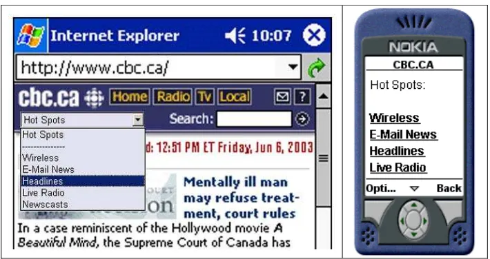
The Quick Access pattern is identified by further abstracting the “hot spot” related aspects of the dialog and presentation model. In order to migrate the hot spot toolbar to the PDA and the mobile phone environment the Quick Access pattern needs to be re-instantiated. For the sake of this example, the pattern is instantiated as a combo box for the PDA platform whereas on the mobile phone the pattern is presented as a simple list.
During forward engineering the effected models are established and eventually re-implemented Figure 10 displays a possible implementation of the “hot spots” for the PDA and mobile phone.
Figure 10: Hot Spot Implementation for PDA and Mobile Phone
Conclusions
It was demonstrated how components can be used to implement knowledge captured by patterns. The relation between patterns and components was discussed in detail and a patterns and components based development process model was provided. Additionally, it was discussed how tool support could be provided. Two case studies of the usage of UI patterns were discussed. The first one was a project to develop a software system. The second one described the reengineering process of a CNN web page to develop user interfaces for mobile devices. We strongly believe that pattern and components are very important for the software development of the future. The outlined development models provide a lot of advantages.
References:
[Balzert 96] Balzert, H.: From OOA to GUIs: The JANUS System. Journal of Object-Oriented
Programming, (Febr. 1996), pp.43-47.
[Bouillon et. al. 04] Bouillon, L., J. Vanderdonckt and C. K. Chow: Flexible re-engineering of web sites. In Proceedings of Intelligent User Interfaces (IUI), Madeira, Portugal, pp. 132-139.
[Chikofsky et. al. 90] Chikofsky, E. J. and J. H. Cross: Reverse Engineering and Design Recovery - A Taxonomy. IEEE Software, pp.13-17.
[Gaedtke et. al 2000] Gaedke, M., C. Segor and H.-W. Gellersen: WCML: Paving the Way for Reuse on Object-oriented Web-Engineering. In Proc. of SAC 2000, Villa Olmo, Como, Italy, pp. 74-77.
[Märtin 96] Märtin, C.: Software Life Cycle Automation for Interactive Applications: The AME Design Environment. In Proc. of CADUI'96, Namur, Belgium, Namur University Press, pp. 57-76.
(MOBI-D 99]MOBI-D: The MOBI-D Interface Development Environment [Internet]. Available from <http://smi-web.stanford.edu/projects/mecano/mobi-d.htm> [Accessed February, 2004].
[Moore 94] Moore, M.: A Technique for Reverse Engineering User Interfaces. In Proceedings of
Fourth Reverse Engineering Forum, November, 1994, Victoria, British Columbia.
[Moore 96] Moore, M.: Representation Issues for Reengineering Interactive Systems. ACM
Computing Surveys, 28/4.
[Paternò00] Paternò, F.: Model-Based Design and Evaluation of Interactive Applications, Springer.
[Program-Transformation.Org 04] Program-Transformation.Org: Reengineering [Internet]. Available from <www.program-transformation.org/re/> [Accessed May, 2004].
[Schmidt et. al. 99] Schmidt, A., M. Beigl and A. Gellersen: There is more to Context than Location.
Computers & Graphics Journal, 23, pp.893-902.
[Shilit et. al. 93] Shilit, B., M. Theimer and B. Welch: Customizing Mobile Applications. In
Proceedings of USENIX symposium on Mobile and Location-independent Computing, pp. 129-138.
[Sinnig 04] Sinnig, D.: The Complicity of Patterns and Model-Based UI Development. Master Thesis in the Department of Computer Science, Concordia University, Montreal.
[SWING 02] SWING: Pluggable Look & Feel [Internet]. Available from <http://www.manning.com/sbe/files/uts2/Chapter21html/Chapter21.htm> [Accessed May, 2004].
[Szyperski 98] Szyperski, C.: Component Software - Beyond Object-Oriented Programming, Addison-Wesley / ACM Press.
[TERESA 04] TERESA: Transformation Environment for Interactive Systems Representations
[Internet]. Available from <http://giove.cnuce.cnr.it/teresa.html> [Accessed February, 2004].
[Tidwell 04] Tidwell, J.: UI Patterns and Techniques [Internet].
Available from <http://time-tripper.com/uipatterns/index.php> [Accessed January, 2004].
[Vanderdonckt 03] Vanderdonckt, J., E. Furtado, J. Furtado and Q. Limbourg: Multi-Model and Multi-Level Development of User Interfaces. Multiple User Interfaces, Cross-Platform Applications
and Context-Aware Interfaces, London, Wiley, pp.193-216.