AN EMBEDDED WEB SERVER-BASED REMOTE MONITORING SYSTEM
TAN JIN HONG
“I hereby declared that I have read through this report and found that it has comply
the partial fulfillment for awarding the degree of Bachelor of Electrical Engineering
(Power Electronic and Drives)”
Signature : ……….
Supervisor’s Name : Professor Madya Dr. Zulkifilie bin Ibrahim
AN EMBEDDED WEB SERVER-BASED REMOTE MONITORING SYSTEM
TAN JIN HONG
This Report Is Submitted In Partial Fulfillment Of Requirements For The Degree Of Bachelor In Electrical Engineering (Power Electronic and Drives)
Fakulti Kejuruteraan Elektrik Universiti Teknikal Malaysia Melaka
ii
“I hereby declared that this report is a result of my own work except for the excerpts
that have been cited clearly in the references.”
Signature : ……….
Name : TAN JIN HONG
Abstract
To design and develop an embedded web server using 8-bit microprocessor and
TCP/IP Ethernet connection for office/home automation applications. In this project, the
controller developed is based on Rabbit microprocessor and its core module model RCM
3700. Controlling the motor and others I/O like sensor and also alarms through a website
base controller. Showing the I/O data through RCM 3700 with the TCP/IP Ethernet
connection to personal computer in webpage. The webpage and firmware will be done in
Dynamic C programming language.
For a controlling system, most of last time technology is on short distance
controlling system, for example, a control system that builds in a system like a car
manufacture system at 1970th. The use of internet and local area network at that time is
not common so the range control system is quite difficult at that time. For the present day,
the long range control system is become very common. Many types of controlling system
are developed for long range control system. For example, the controlling of the Lander
Beagle 2 (a remote control car that send to the Mars). At the future, this long range
control technology may be developing in the speed of communication. The controlling
reaction time may be become as fast as the speed of light or may be faster than the light
speed.
For the hardware development, I have to do the connection to connect the I/O like
motor to the RCM 3700 board. For the software part, I have to develop the embedded
Abstrak
Projek ini bertujuan untuk mengubasuai dan mencipta satu embedded web server
dengan mengunakan 8-bit microprocessor dan TCP/IP Ethernet connection untuk
kegunaan automasi pejabat dan rumah. Projek ini megunakan Rabbit microprocessor and
its core module model RCM 3700. Projek ini akan mengawal motor dan I/O yang lain
seperti sensor dan relay melalui laman web. I/O akan ditunjukkan melalui RCM 3700
dengan TCP/IP Ethernet connection kepada computer peribadi di laman web.
Untuk system control, kebanyakkan teknologi lama menggunakan control system
yang hanya boleh berkomunikasi berdekatan. Kegunaan internet dan local area network
tidak digunakan dengan luas pada masa itu. Untuk masa kini, control melalui internet
adalah sangat biasa. Banyak jenis long range control system telah dibuat hari ini sebagai
contohnya control Lander Beagle 2 (satu kereta remote control yang di hantar ke Mars).
Untuk masa depan, kelajuan communikasi akan dipentingkan. Sebagai contohnya, pada
masa akan datang data – data yang dihantar mungkin akan mencapai kelajuan hadlaju
cahaya dan mungkin melebihi hadlaju cahaya.
Untuk bahagian perkakasan, saya akan membuat perikatan dengan I/O untuk
menghubungi RCM 3700 board. Untuk bahagian perisian, saya membuat develop dengan
embedded laman web software untuk membolehkan computer peribadi bercommunikasi
CONTENTS
CHAPTER TITLE PAGE
ABSTRACT III
ABSTRAK IV
CONTENTS V
LIST OF TABLES VI
LIST OF FIGURES VII
LIST OF APPENDIX VIII
I INTRODUCTION
1.1 Objectives of the project 2
1.2 Project scopes 3
1.3 Problem statement 3
1.4 Project Planning 4
II LITERATURE REVIEW
2.1 Remote Monitoring System 5
2.1.1 Embedded Web-server-monitoring System
and CDMA Service (Crop Field Remote
Monitoring system)
5
2.1.2 GSM-SMS Based Remote and Control
System for Greenhouse Application
6
2.1.3 The 3G-Based Wireless Networked &
Intelligent Monitoring System (Pharos
Management)
7
2.1.4 Remote Telephone-Controlled System
(Home Automation)
v
2.1.5 Remote Monitoring over Internet
(Air-Quality)
9
2.2 Computer network 11
2.2.1 LAN (Local Area Network) 12
2.2.2 WAN (Wide Area Network) 13
2.2.2.1 WAN connectivity options 14
2.2.3 Client/Server Networks 15
2.2.4 Port Numbers 16
2.2.5 TCP/IP protocol 17
2.2.5.1 Network Protocol Layers 18
2.2.5.2 Layering Models 18
2.2.5.3 Application layer 19
2.2.5.4 Transport layer 20
2.2.5.5 Network layer 23
2.3 Embedded Web Server 23
2.3.1 Typical requirements 24
2.3.2 Open source servers 25
2.3.2.1 Jetty 25
2.3.2.2 Java Mini Daemon 25
2.3.2.3 Yaws 25
2.3.2.4 AppWeb 26
2.4 RCM 3700 Rabbit microprocessor 26
2.5 GIF (Graphics Interchange Format) 27
2.6 HTML (Hypertext Markup Language) 27
III METHODOLOGY
3.1 Process flow 28
3.2 Block diagram of An Embedded Web
Server-based Remote Monitoring System.
30
3.3 Dynamic C 32
3.3.1 Speed 32
3.3.2 Dynamic C Enhancements and Differences 33
3.3.4 Dynamic C Differences 33
3.4 TCP Header 35
3.5 Memory Mapping for Rabbit
Microprocessor
37
3.6 Rabbit 3000 Microprocessor 39
3.7 Rabbit Core Module 3700 40
3.7.1 RCM3700 Features 41
3.7.2 Advantages of the RCM3700 42
3.7.3 Power Supplies 42
3.7.4 The Ethernet port 43
3.8 RCM 3700 Prototype Board 44
3.8.1 Prototyping Board Features 45
3.8.2 Power Supply 45
3.8.3 Analog Features 46
3.8.4 A/D Converter Inputs 46
3.8.5 Thermistor Input 48
3.9 Thermistor 49
3.10 Photocoupler or optocoupler 51
3.11 DC Motor 52
3.12 Laboratory Power Supply 53
3.13 Hardware Setup and Integration 54
3.13.1 RCM3700 and its Prototyping Board Setup 54
3.13.2 Relay board 57
3.13.3 Hardware Integration 57
IV APPLICATION
4.1 Program function prototype 60
4.1.1 Setting the IP address for the RCM 3700
board.
60
4.1.2 Controlling DC motor via webpage 63
4.1.2.1 The program source code (Dynamic C
language), development and explanation
63
v
motor via webpage
4.1.2.3 The program source code (Webpage html
and SSI language), development and explanation
73
4.1.3 Running procedure 75
V CONCLUSION
5.1 Suggestion and Future Work 83
REFERENCES
85
LIST OF TABLES
NO TITLE PAGE
1.1 The Gantt chart shows the project planning of the major activities
in PSM1 and PSM2
4
2.1 WAN connectivity 14
2.2 The Summary of Differences between Client and Server 15
2.3 TCP port number 16
2.4 ISO 7-Layer Reference Model 18
2.5 TCP/IP 5-Layer Reference Model 19
3.1 Summarizes the main features of the RCM3700 41
vii
LIST OF FIGURES
NO TITLE PAGE
2.1 LAN connection flow 11
2.2 TCP/IP protocol flow 17
2.3 Three – way handshake 22
3.1 Process Flow 28
3.2 Block diagram of An Embedded Web Server-based Remote
Monitoring System
30
3.3 The Synchronizing Sequence Numbers for TCP Connection 35
3.4 Actual memory mapping for main function of web base remote
and controlling system
38
3.5 Rabbit microprocessor 39
3.6 Rabbit Core Module 3700 40
3.7 Rabbit Core Module 3700 40
3.8 Rabbit Core Module 3700 Power Supply 42
3.9 The Ethernet 43
3.10 RCM 3700 Prototype Board 44
3.11 RCM 3700 Prototype Board 44
3.12 The Prototyping Board Power Supply 46
3.13 A/D converter input circuits 46
3.14 Thermister Input Circuit 48
3.15 Thermister 50
3.16 Photocoupler 51
3.17 DC motor 52
3.18 Power Supply 53
3.19 Prototyping Board Setup 54
3.21 Prototyping Board Setup 55
3.22 Relay board 57
3.23 Overall schematic 58
3.24 Hardware interfacing 59
4.1 Setting the IP address 60
4.2 Setting flow for server IP 1 61
4.3 Setting flow for server IP 2 62
4.4 Setting flow for server IP 3 62
4.5 Main function 71
4.6 Function of toggle led on webpage 71
4.7 Function of update outputs of led 72
4.8 Webpage overview 75
4.9 Insert IP address 76
4.10 Normal stage 77
4.11 Normal stage 77
4.12 Normal stage 78
4.13 Normal stage 78
4.14 Automatic stage 79
4.15 Automatic stage 80
4.16 Interrupting stage 80
4.17 Interrupting stage 81
4.18 Interrupting stage 82
1
CHAPTER 1
INTRODUCTION
Nowadays, controlling a system via PC is very common. A web base control
and monitoring system can make us control a system without distance. So developing
a cost effective, programmable and high efficiency controller webpage is necessary
for the world competition.
This project is titled as “An Embedded Web Server-based Remote
Monitoring System”. The propose of this project is to build a remote control system
through a webpage. And this system is controlled through local area network by
using an embedded TCP/IP Rabbit Core Module 3700. The RCM 3700 is chosen
because of have easy Program download utility, ideal for network-enabling security
and lots of storage.
This project is divided to hardware and software part. The hardware part is
building up an I/O that can connect to the RCM 3700. The connection between the
Input/output is connected by a converter that can convert the hardware like sensor
and motor signal for RCM 3700.
For the software part, webpage base embedded software will be build for
enable personal computer to communicate with RCM 3700 by using Dynamic C. The
changing in the I/O will be shown in the personal computer by accessing the
1.1 Objectives of the project
1. Controlling and monitoring a control system through webpage.
2. A personal computer will become a client and the rabbit microprocessor will
be a server.
3. Controlled through local area network by using embedded TCP/IP Rabbit
Core Module 3700 RCM 3700 as a server.
4. Design and develop an I/O interface for extended device connection to the
RCM3700.
5. Develop Webpage application software will run at the PC platform.
6. Develop Webpage base embedded software will be design and develop for
communication between personal computer with RCM 3700 by using
Dynamic C via local area network (LAN).
7. Controlling and monitoring the I/O like motor, sensor, relay and led via
3
1.2 Project scopes
1. Study the architecture design and technical specification of embedded Rabbit
microprocessor base controller.
2. Study the TCP/IP connection protocol.
3. Study the Dynamic C programming language environment.
4. Develop web server program.
5. Develop firmware for RCM 3700.
6. Design and develop I/O interface for devices connection like relay, sensor
and motor.
7. Run the prototype controller in real-time and debug.
1.3 Problem statement
1. Controlling a system via PC is very common but PC is too expensive and
cannot work continuously for long working time.
2. A web base controlling system can make us control a system without distance.
3. Controlling a webpage use the PLC based controller is very difficult because
the programming language too complex.
4. Developing a cost effective, programmable and reliable embedded web
controller webpage is necessary for the world competition.
5. The Rabbit microprocessor is chosen because it provide embedded based for
remote automation applications like office or factory application controller
that can provide good environment for webpage controlling system.
6. Integrated hardware and software development and build in with TCP/IP
1.4 PERANCANGAN PROJEK
PROJECT PLANNING
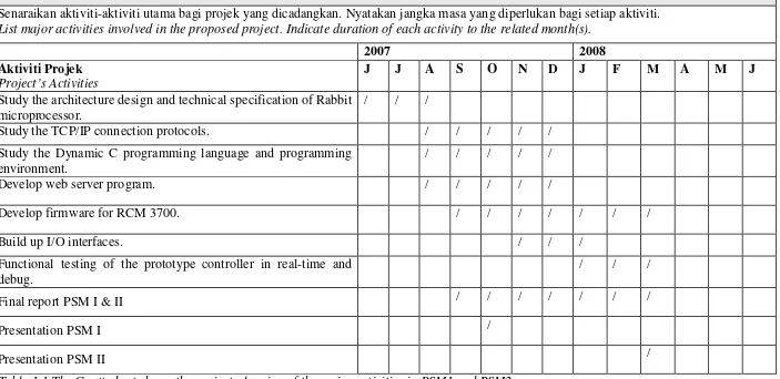
Senaraikan aktiviti-aktiviti utama bagi projek yang dicadangkan. Nyatakan jangka masa yang diperlukan bagi setiap aktiviti.
List major activities involved in the proposed project. Indicate duration of each activity to the related month(s).
2007 2008
Aktiviti Projek
Project’s Activities
J J A S O N D J F M A M J
Study the architecture design and technical specification of Rabbit microprocessor.
/ / /
Study the TCP/IP connection protocols. / / / / /
Study the Dynamic C programming language and programming environment.
/ / / / /
Develop web server program. / / / / /
Develop firmware for RCM 3700. / / / / / / /
Build up I/O interfaces. / / /
Functional testing of the prototype controller in real-time and debug.
/ / /
Final report PSM I & II / / / / / / /
Presentation PSM I /
[image:17.842.73.776.102.444.2]Presentation PSM II /
5
CHAPTER 2
LITERATURE REVIEW
2.1 Remote Monitoring System
The remote and monitoring system can be control by many kind of different
technology. The progress can be control and monitor system via field bus, and
Ethernet, power line carrier, SMS, EPRS, ADSL, GPRS, CDMA-Based, 3G-Based
wireless network, telephone control and other communication means are applied to
realize data transmission between data acquisition modules and data collection center.
The remote and monitoring able system can be the temperature control and
monitoring system, streetlight monitors and control system, remote monitoring of
air-quality system, online power system, crop field remote monitoring system,
remote measurement and control system for greenhouse, home automation system
and some other system that will appear on our living life.
2.1.1 Embedded Web-server-monitoring System and CDMA Service (Crop Field Remote Monitoring system)
Remote monitoring systems based on web-server-embedded technology and
mobile telecommunication will become a core node technology in sensing network
construction because of a great deal of mobile users and spreads of digital services in
next generation telecommunication in the world. Soil, environmental, and crop
information monitoring are important in production management and
decision-making in precision agriculture. Therefore, reliability, security and inexpensive
characteristics required will be essential in the crop field information monitoring.
(CDMA) services combined with IPSec-based virtual private network (VPN)
function have installed to two rice practical fields in Shanghai and one maize
experimental field in Beijing for constructing a remote wireless sensing network. [1]
This crop field remote monitoring system as a ubiquitous node infrastructure
in wireless sensing networks is useful and powerful to collect soil, environment, and
crop information in remote for precision agriculture. The real-time soil and
environment data, and crop images can be dynamically collected in remote area by
the crop field monitoring systems in remote. This crop field remote monitoring
system using web-server-embedded technology and CDMA service with
IPSec-based VPN function as a node infrastructure is powerful and useful to construct a
ubiquitous wireless sensing network in low-cost and high-security for crop
production. [1]
2.1.2 GSM-SMS Based Remote and Control System for Greenhouse Application
GSM (Global System for Mobile Communications), SMS (Short Message
Service).
Global System for Mobile communications is the most popular standard for
mobile phones in the world. Its promoter, the GSM Association, estimates that 82%
of the global mobile market uses the standard. GSM is used by over 2 billion people
across more than 212 countries and territories. Its ubiquity makes international
roaming very common between mobile phone operators, enabling subscribers to use
their phones in many parts of the world. GSM differs from its predecessors in that
both signaling and speech channels are digital call quality, and thus is considered a
second generation (2G) mobile phone system. This has also meant that data
communication was easy to build into the system.
Short Message Service (SMS) is a communications protocol allowing the
interchange of short text messages between mobile telephone devices. The SMS
technology has facilitated the development and growth of text messaging. The
7
technology is so great that in parts of the world the term "SMS" is used colloquially
as a synonym for a text message from another person or the act of sending a text
message. SMS as used on modern handsets was originally defined as part of the
GSM series of standards.
As a new planting mode, modern greenhouse installations are marked by their
high efficiency and uniformity in production of vegetable, fruitage, flower, medicinal
materials, and others. The new mode breaks the restriction of region, environment,
climate and other factors, and has become an incomparable planting mode. It can
efficiently improve the agriculture ecology and production condition while
promoting the scientific exploitation and reasonable use of agriculture resource.
Moreover, output rate of earth as well as working efficiency is enhanced, and good
social and economic benefits are received. Survey and control of greenhouse
environment parameter is the key part in the realization and development of
greenhouse installations. [2]
A greenhouse environment measurement and control system based on
GSM-SMS was developed. The system adopted mobile communication between computer
and microcontroller; it comprises a centre station and some base stations. The central
station consists of a server together with its application software, a GSM module and
a database system; the base station consists of a microcontroller, sensors, actuators
and a GSM module. Modularization design procedures were taken in hardware and
embedded operating system in software development, which make it easy to extend,
maintain and update the system. [2]
2.1.3 The 3G-Based Wireless Networked & Intelligent Monitoring System (Pharos Management)
An intelligent monitoring system of pharos based on GSM/GPRS, GPS and
GIS short message service is introduced. For the data collection, data treatment and
GSM/GPRS-base data communication are implemented via field instrument. The
working states and messages of pharoses, including working current and voltage,
unloading voltage, GPS parameters and other environment information, are sent by
management center and the mobile telephone of manager on the watch. So the
central computer of the system is able to carry out centralized management of data
and remote control for wireless remote monitoring of pharoses. [3]
In practical application of pharos management system, the information
transferred via SMS include parameters like location of pharos, charging current,
battery cell voltage, load current and other working states. The implementation of
intelligent management on pharos with GSM & SMS technology, as a wireless
remote monitoring system, it is of wide application. In the navigation channel
management, pharoses spread widely in inland and near-sea. To check the status of
these pharoses artificially not only cost a great deal of man power and material
resources, but the inspection cannot be done in time. Even worse, sometimes the
artificial operation may endanger man's life. It has gear significance to apply wireless
monitoring system of pharos for improving the management level &quality of pharos
and navigation. [3]
2.1.4 Remote Telephone-Controlled System (Home Automation)
Home Automation System using telephone lines, will be consists of two
subsystems. One is the Remote Control system. The other one is the Phone
Monitoring system. The Remote Control system used the Dual Tone Multi-frequency
signals to control the operations of various appliances. The hardware and software
are designed based on the standard telephone system. The Phone Monitoring system
provides convenient services for the user to better monitoring the usage of their
phones. [4]
The systems can be installed for public use widely. Both systems were
designed based on the DTMF (Dual Tone Multi-frequency) signals that are produced
by the telephone system. The DTMF signals were sent from the user end to the
destination end. The RC (Remote Control) system detects the number of phone ring
and a set of defined codes to determine if a remote control signal has been sent out to
control the operation of target appliance. If the control signal is confirmed by the
system, the system will send out a control signal to initiate the operation of the
9
automatically record the content of the conversation if it detects an in or out call of
the phone.
The remote control system provides a couple of convenient services to
promoting the living lives of families. The users have better control on their home
appliances. This is especially important if they need such a control when they are far
away from the location of their homes. This remote control style can also be applied
to the control of factories. A careful design can possibly reduce the operation cost.
The phone monitoring system can record the conversation on the phone. The circuit
is quiet small and can be insert in telephone set easily. The circuit can be installed in
series with the phone lines. The serial resistance is below 100 ohms. Therefore, the
circuit will not affect the performance of telephones. [4]
The circuit extracts the power from the phone line directly and has low power
dissipation. Therefore, there are no battery and antenna in the circuit. The user can
listen to the conversation far to 25 meters. A commercial cascade player can record
the conversation easily. The parents can use the utility to better understand the
development of their children. By the way, the bulb wills turn on automatically when
the phone is ringing. This function will be helpful in lighting up the room for picking
up the phone when a deep night call is coming. The design of a remote control
system and a phone monitoring system. Both systems are operated based on the
standard telephone lines. People can have better control on their house and their lives
even they are traveling in another country. [4]
2.1.5 Remote Monitoring over Internet (Air-Quality)
Air-quality remote monitoring systems, consists of monitoring controllers,
monitoring agents, MNIB (MoNitor Information Base), protocols and the Internet.
The air-quality monitoring systems will in 4 models: organization model,
information model, communication model and functionality model. The information
model deals with monitoring information structure and MNIB. The basic unit of
monitoring information is a monitored object with 6 attributes. MNIB takes a
tree-like structure and its leaves store a monitored object. The communication model
controllers and monitoring agents. The system devise a proprietary network
application layer protocols, termed as ARMP (Air-quality Remote Monitor Protocol),
dedicated to air-quality remote monitoring systems. ARMP operates in four modes:
monitor, monitor-next, set and trap. [5]
In Monitor mode, a monitoring controller will send a request to monitoring
agents, and specify the pollutants. The Set mode is designed for a monitoring
controller to write values to monitored objects in a monitoring agent. After Set
operation, the monitoring agent will return to the monitoring controller for response
with the same value in the object-bindings and with status information indicating
whether the Set operation is successful in addition. It should be noted that the
monitoring agent, instead of the monitoring controller, is active in the Trap operation.
The monitoring agent initiates a communication session with a monitoring controller
11
2.2 Computer network
A computer network is an interconnection of a group of computers. Networks
may be classified by what is called the network layer at which they operate according
to basic reference models considered as standards in the industry such as the
four-layer Internet Protocol Suite model. While the seven-four-layer Open Systems
Interconnection (OSI) reference model is better known in academia, the majority of
networks use the Internet Protocol Suite (IP) as their network model.
[image:24.595.123.456.306.521.2]2.2.1 LAN (Local Area Network)
Figure 2.1 LAN connection flow
A local area network (LAN) is a computer network covering a small
geographic area, like a home, office, or group of buildings. The defining
characteristics of LANs, in contrast to Wide Area Networks (WANs), include their
much higher data transfer rates, smaller geographic range, and lack of a need for
leased telecommunication lines. [6]
Ethernet over unshielded twisted pair cabling, and Wi-Fi are the two most
common technologies currently, but ARCNET, Token Ring and many others have
been used in the past. Although switched Ethernet is now the most common data link