8/15/2014 Vol 64, No 4
http://www.jurnalteknologi.utm.my/index.php/jurnalteknologi/issue/view/115 1/3
JOURNAL HELP
USER Username Password
Remember me Login
NO TI F I CA TI O NS View
Subscribe
J O URNA L CO NTENT Search
All Search
Browse By Issue By Author By Title
F O NT SI ZE
I NF O RMA TI O N For Readers For Authors For Librarians
CURRENT I SSUE
HO ME ABO UT LO GIN R EGISTER SEAR C H C UR R ENT AR C HIVES
ANNO UNC EMENTS SUBMISSIO NS P ENER BIT UTM P R ESS UTM
Home > Archives > Vol 64, No 4
Vol 64, No 4
Special Edition
Table of Contents
Science and Engineering
Electrical Characteristics of Polyvinyl Chloride with Wollastonite Filler for High Voltage Outdoor Insulation Material
M. M. Yaacob, N. Kamaruddin, N. A. Mazlan, N. F. Noramat, A. Aman, M. A. Alsaedi
Review of Partial Discharge Signal Monitoring In Power Transformer Using Chromatic Approach
M. M. Yaacob, Malik Abdulrazzaq Alsaedi
An Experience of Ageing on XLPE Insulation PDF
W. G. Ariastina, A. I. Weking, I. N. S. Kumara, I. A. D. Giriantari, I. N. Sugiarta
Space Charge Distribution in a Dielectric Liquid Using an Optical Method
Haruo Ihori, Hayato Nakao, Masaki Takemura, Mitsuru Oka, Hyeon-Gu Jeon, Masaharu Fujii
Electrical Tree Growth in Silicone Rubber/Organo-Montmorillonite Nanocomposites under AC Ramp Voltage
A. A. A. Jamil, M. H. Ahmad, Y. Z. Arief, M. Kamarol, M. Mariatti, N. Bashir, M. A. M. Piah
Thermal Image and Leakage Current Diagnostic as a Tool for Testing and Condition Monitoring of ZnO Surge Arrester
Novizon N., Zulkurnain Abdul Malek, Nouruddeen Bashir, N. Asilah
Effects of Lightning Current and Ground Conductivity on the Values of Vertical Electric Fields
M. Izadi, M. Z. A. Ab Kadir, M. Hajikhani, N. Rameli
Condition Assessment of High Voltage Instrument Transformer Using Partial Discharge Analysis
8/15/2014 Vol 64, No 4
http://www.jurnalteknologi.utm.my/index.php/jurnalteknologi/issue/view/115 2/3
Kannan
Comparative Study on Space Charge Distribution Measurements using PEA and PWP Methods on High Voltage Insulation
N. A. Othman, M. A. M. Piah, Z. Adzis, N. A. Ahmad
RVM versus PDC Methods for Insulations’ Conductivity and Moisture Content Monitoring
R. A. Zainir, N. A. Muhamad, Z. Adzis, M. A. M. Piah, N. F. Kasri, N. A. M. Jamail
Effect of Switching Method in Polarization and Depolarization Current (PDC) Measurement Technique
N. F. Kasri, M. A. M. Piah, N. A. Muhamad, N. A. M. Jamail
Pearl-chain-type Trees in Silicone Gel Under AC Voltage PDF
Masaharu Fujii, Haruo Ihori, Hyeon-Gu Jeon
Study On Pollution Performance on a Wind Turbine Blade Using OES Technique for Lightning and Switching Impulse Voltage Profiles
V. Sathiesh Kumar, Nilesh J. Vasa, R. Sarathi
Breakdown Strength Characteristic of RBDPO and Mineral Oil Mixture as an Alternative Insulating Liquid for Transformer
Yusnida M., Kiasatina Azmi, Mohd Azmier Ahmad, Zulkifli Ahmad, Mohamad Kamarol
Localised Single-Station Lightning Detection by Using TOA Method PDF
Behnam Salimi, Zulkurnain Abdul-Malek, Kamyar Mehranzamir, Saeed Vahabi Mashak, Hadi Nabipour Afrouzi
Solar Array and Battery Sizing for a Photovoltaic Building in Malaysia
Hadi Nabipour Afrouzi, Saeed Vahabi Mashak, Zulkurnain Abdul-Malek, Kamyar Mehranzamir, Behnam Salimi
Investigation of Ferroresonance Mitigation Techniques in Voltage Transformer Using ATP-EMTP Simulation
Zulkurnain Abdul-Malek, Kamyar Mehranzamir, Behnam Salimi, Hadi Nabipour Afrouzi, Saeed Vahabi Mashak
Effect of Water on Electrical Properties of Refined, Bleached, and Deodorized Palm Oil (RBDPO) as Electrical Insulating Material
Nazera Ismail, Yanuar Z. Arief, Zuraimy Adzis, Shakira A. Azli, Abdul Azim A. Jamil, Noor Khairin Mohd., Lim Wen Huei, Yeong Shoot Kian
Influence of Organo-Montmorillonite on Electrical Tree Parameters in Epoxy Resin Under Ac Ramp Voltage
Mohd Hafiez Izzwan Saad, Mohd Hafizi Ahmad, Yanuar Z. Arief, Hussein Ahmad, Mohamed Afendi Mohamed Piah
Data Transmission System of Rotating Electric Field Mill Network Using Microcontroller and GSM Module
8/15/2014 Vol 64, No 4
http://www.jurnalteknologi.utm.my/index.php/jurnalteknologi/issue/view/115 3/3
Muhammad ‘Irfan Jambak
Development and Study on Transformer Characteristics of A High Repetition Pulse Generator
Muhammad Abu Bakar Sidik, Hamizah Shahroom, Hussein Ahmad, Zolkafle Buntat, Zafar Iqbal, A. S. Samosir, Zainuddin Nawawi, Muhammad 'Irfan Jambak
Atmospheric Electric Field Data Logger System PDF
Muhammad Abu Bakar Sidik, Nuru Saniyyati Che Mohd Shukri, Hussein Ahmad, Zolkafle Buntat, Nouruddeen Bashir, Yanuar Zulardiansyah Arief, Zainuddin Nawawl, Muhammad 'Irfan Jambak
Phenol Removal from Water by Pulsed Power Discharge: A Review PDF
Hashem Ahmadi, Muhammad Abu Bakar Sidik, Mehrdad Khamooshi, Zulkafle Buntat
On-Site Partial Discharge Monitoring System in Generator at Tanjung Bin Power Plant, Johor, Malaysia
A. H. Muhamad, Y. Z. Arief, W. A. Izzati, Z. Adzis, M. A. B. Sidik
An Experimental Study on Surface Discharge Characteristics of Different Types of Polymeric Material under AC Voltage
N. Baharin, Y. Z. Arief, W. A. Izzati, M. Z. H. Makmud, Z. Adzis, M. A. B. Sidik
Polarization and Depolarization Current Measurement of Polymer Added with Nano-particles of Silicon Oxide For HV Insulation
N. A. M. Jamail, M. A. M. Piah, N. A. Muhamad, R. A. Zainir, N. F. Kasri, Q. E. Kamarudin
An Experience of Ageing on XLPE Insulation PDF
W. G. Ariastina, A. I. Weking, I. N. S. Kumara, I. A. D. Giriantari, I. N. Sugiarta
Evaluation of Lightning Induced Voltage due to the Effect of Design Parameters on Medium Voltage Distribution Line
N. Rameli, M. Z. A. Ab Kadir, M. Izadi, C. Gomes, J. Jasni
Effect of Ambient Temperature on Leakage Current of Gapless Metal Oxide Surge Arrester
C. L. Wooi, Zulkurnain Abdul-Malek, Saeed Vahabi Mashak
Copyright © 2012 Penerbit UTM Press, Universiti Teknologi Malaysia.
Disclaimer : This w ebsite has been updated to the best of our know ledge to be accurate. How ever, Universiti Teknologi Malaysia shall not be liable for any loss or damage caused by the usage of any information obtained from this w eb site.
64:4 (2013) 13–17 | www.jurnalteknologi.utm.my | eISSN 2180–3722 | ISSN 0127–9696
Full paper
Jurnal
Teknologi
An Experience of Ageing on XLPE Insulation
W. G. Ariastinaa*, A. I. Wekinga, I. N. S. Kumaraa, I. A. D. Giriantaria,I. N. Sugiartab aDepartment of Electrical Engineering, Udayana University, Bali-80362, Indonesia
bPT PLN (Persero) Distribution of Bali, South Bali Network Area, Bali-80113, Indonesia
*Corresponding author: [email protected]
Article history
Received :15 February 2013 Received in revised form : 10 June 2013
A case study of ageing on XLPE conductor insulation of 20kV primary distribution feeder is presented in this paper. The insulation degradation mainly occurred around conductor tie where the conductor is attached to the post insulator. A section of distribution feeder with defects on the conductor insulation has been examined for this study. Potential losses due to presence of discharges have been investigated by measuring the difference current at locations of the affected conductor. Temperature measurements of the insulation surface have also been carried out. Provisional maintenance procedures were introduced to eliminate the discharges. Measurements of current and surface temperature were repeated nine months after completion of the maintenance work. Results indicated that the discharges have been completely disappeared.
Keywords: XLPE insulation; ageing; partial discharges
© 2013 Penerbit UTM Press. All rights reserved.
1.0 INTRODUCTION
In order to maintain reliability of a distribution network, it is important to choose an appropriate size and type of conductor. There are a number of available conductors for electric power distribution feeder. Bare conductors are usually applied for the distribution networks. In case where a distribution network route passes coastal area, the application of aluminium conductor is preferred, because of the corrosion withstand characteristic of the aluminium. Among other aluminium conductors, the AAC (all aluminium conductor) and AAAC (all aluminium alloy conductor) are well known for their excellent performance. Recently, the utilisation of AAAC-S (all aluminium alloy conductor – sheathed) for distribution network has been broadened, particularly in South and East part of Bali. In these parts of the island, most of the distribution networks are supplying consumers at tourism areas near beaches. It is well known that the utilisation of the AAAC-S has a number of advantages compared to that of the bare conductors. The AAAC-S has an ability to protect the distribution network from temporary disturbances which are mainly caused by falling kite and nearby tree contacts. Direct contact of airborne pollutants with the conductor strands may also be avoided.
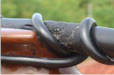
Nevertheless, after a few years of utilisation, problems began to appear on the insulation of the AAAC-S. It was found that the XLPE sheath degrade rapidly, particularly near the insulator tie. Tiny sparks at the degraded sheath section can be observed clearly at night, indicating the occurrence of discharges. Visual observation of the conductor insulation during day time showed burnt sections around the conductor tie. At some sections, the XLPE sheath has been completely disappeared. This situation obviously requires immediate attention and appropriate maintenance measures.
14 W. G. Ariastina et al. / Jurnal Teknologi (Sciences & Engineering) 64:4 (2013), 13–17
Figure 1 Sheath degradation of AAAC-S
The occurrence of discharges on the distribution network absolutely causes energy losses. The amount of energy loss very much depends on the characteristics of discharges occurred on the conductor. This paper discusses the potential losses due to degradation of the AAAC-S conductor insulation applied to distribution network. Investigation was carried out on a section of 20kV primary distribution feeder. The section consists of 12 poles at which insulation defects were preliminary identified. Flowing current and surface temperature of the conductor were measured around the conductor tie for each pole. The measurements of current and surface temperature were carried out during dry season to reduce risk of being electrified. A comparison of measurement results before and after planned maintenance operation is also discussed in this paper.
2.0 THE AAAC-S CONDUCTOR
The AAAC and AAAC-S are available in different sizes of cross section areas. The 150 and 240mm2 conductors are mostly used
for primary power distribution networks in Bali. Typical technical requirements for the AAAC are presented in Table 1. The requirements of the AAAC-S are fairly similar to those of the AAAC, except it is sheathed with 3mm extruded XLPE, thus increasing the overall diameter of the conductor.
Table 1 Technical requirements for AAAC1
No Properties Requirements
1 Maximum specific DC resistance at 20°C 0.0328 .mm2/m
2 Specific weight at 20°C 2.70 kg/dm3
3 Length expansion coefficient 23 x 10-6/°C
4 Temperature coefficient (α) at 20°C between 2 potential points on the conductor
0.00360/°C
5 Minimum purity of aluminium alloy 97.28%
Magnesium 0.5%
Silicon 0.5%
The XLPE sheath of the conductor however, is not designed to completely isolate the conductor and only be able to prevent temporary disturbances at some points. The conductor thus is mainly applied to distribution feeders, which experience frequent temporary disturbances, due to nearby tree or kite contacts with the power lines. The specifications of the conductor have to comply with the PLN Standards 1-3. Figure 2 shows a typical
illustration of the conductor with a peeled sheath on the left end.
1. Conductor strand; 2. Extruded XLPE sheath Figure 2 Illustration of the conductor
3.0 MEASUREMENT OF CURRENT AND TEMPERATURE
The effects of the insulation defects on potential power losses have been investigated on a series of twelve poles with impaired conductor sheath. The poles support conductors that are part of a 20kV primary distribution feeder. The feeder lied adjacent to a main road and is approximately 500m from coast line. There are no electrical loads within the twelve poles 4.
Two medium voltage clamp meters were used to measure potential loss due to the presence of defects. One clamp meter was placed before the conductor tie, while the other was placed after the tie, in referred to the current flow. The difference of current measured between the two is considered as the difference current, and is mathematically expressed as:
ID = │ I1– I0 │ (1)
Note that I0 and I1 respectively denote the current measured
before and after conductor tie, where defects occurred and are referred to the flowing current direction. ID indicates difference
current between I0 and I1. The difference current indicates
potential power losses at the defect location. Measurements of the difference current were carried out for the three phases and for the twelve poles.
Figure 3 depicts the locations of current measurement near a conductor tie of a section with damaged XLPE sheath. The markers on the picture are for indication only. The exact locations of current measurements were further left and right to accommodate all damaged insulation segments. The clamp meter used to measure I1 has similar characteristics to that used to
measure I0.
Figure 3 Location of current measurements
15 W. G. Ariastina et al. / Jurnal Teknologi (Sciences & Engineering) 64:4 (2013), 13–17
Following the identification of the insulation damage, a life maintenance procedure was carried out. This work was aimed to prevent further defect on the conductor strand due to high energy discharges. The work includes tie changed and removal of the affected conductor sheath. Consequently there are some parts of the lines became completely bared at the tie points.
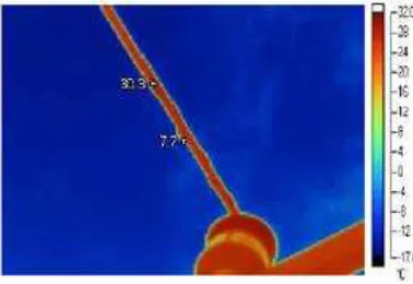
An infrared thermo vision camera was utilised to examine the conductor surface temperature before and after maintenance process. For each location of the degraded insulation, images were taken before and after maintenance works were completed. The temperature difference between the two is defined as:
TD = │ T1– T0 │ (2)
where T1 and T0 respectively denote surface temperature after and
before maintenance. Results of the two measurements then can be compared and analysed. A reduction of surface temperature is expected when the sparks at the degraded insulation are diminished.
Figure 4 shows a typical image from the utilised thermo vision camera. The camera may identify a temperature variation within the aimed area. The average temperature of the conductor sheath near the discharge locations were recorded for this study.
Figure 4 Typical image from the thermo vision camera
4.0 RESULTS AND DISCUSSION
4.1 Current Measurement
Current measurements were carried out before commencing and after completion of planned maintenance works. The measurements and maintenances were carried out during dry season. The current measurement results of the red, yellow and blue phases for the twelve poles before maintenance are presented in Figure 5 to 7. Bars with darker colour indicate incoming current (I0), while those with lighter colour indicate outgoing
current (I1). It is clear that the difference current exists which is
indicating the potential power loss at most of damaged insulation sections.
The measured quantity of flowing current on the conductor depends on the load of the remaining part of the feeder at the time of measurement. The magnitude of difference current varies from point to point of measurements, with an average value of 0.108A for the red phase and of 0.117A for the yellow and the blue phases. This evidence is depicted in Figure 8, where less discharge events occurred on the red phase compared to that on the yellow and blue phases.
0
Figure 5 Measured current of red phase
0
Figure 6 Measured current of yellow phase
0
Figure 7 Measured current of blue phase
0.00
Red Phase Yellow Phase Blue Phase
16 W. G. Ariastina et al. / Jurnal Teknologi (Sciences & Engineering) 64:4 (2013), 13–17 of the total number of poles, the insulation ageing involves two or more phases.
Following the identification of defects on the XLPE insulation, immediate life maintenance works were carried out to prevent further defects on the conductor. Measurements of the flowing current were repeated after completion of the maintenance. There was no indication of difference current during the second measurement.
4.2 Temperature Measurement
As complement of current detection, measurements of surface temperature of the XLPE sheath were also carried out. The temperature of the insulation surface may provide information of existence of discharges. Note that the measured temperature does not indicate the temperature of sparks appeared on some locations of the insulation defects. The indicated values are the average temperature of insulation surface near damaged points. Similar to that of current measurement, the temperature measurement was also carried out before and after the completion of the maintenance works.
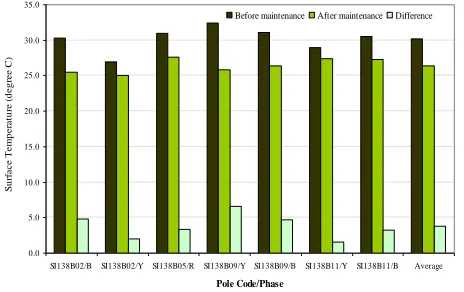
Figure 9 shows the surface temperature of the XLPE sheath before and after maintenance works at a number of investigated poles and particular phases. Note that not all defect points were measured for surface temperature. Measurements were carried out randomly on poles with an identification number of 2, 5, 9 and 11, as shown in the figure. The average temperature of the XLPE sheath surface near defect locations (before maintenance) is slightly above 30°C. In contrast, after completion of the maintenance works, the approximate average XLPE sheath surface temperature became 26.5°C. There was a reduction of about 3.5°C in surface temperature of the XLPE sheath after maintenance process was completed.
0.0
SI138B02/B SI138B02/Y SI138B05/R SI138B09/Y SI138B09/B SI138B11/Y SI138B11/B Average
Pole Code/Phase
Figure 9 Surface temperature of the XLPE sheath
4.3 Discussion
Investigations of ageing in XLPE insulation have been carried out for more than four decades and currently keep advancing 5-11. It
has been known that oxidation and water tree formation may initiate further insulation deterioration of XLPE. The growing water trees obviously change the XLPE properties thus reducing its insulating capability. Defective insulation due to improper
manufacturing process may also be a reason of rapid deterioration of insulating materials. Small cavity within XLPE sheath thus may initiate partial discharges, which further accelerate the ageing process of the insulation.
In early period of utilisation of the AAAC-S in South and East parts of Bali, the installation procedure of the conductor followed the installation of the AAAC. Mishandling of the AAAC-S during installation may damage the XLPE sheath, which is later causing discharges. The presence of discharges and the involvement of water and other pollutants in chemical reactions certainly will further deteriorate the insulation rapidly.
Another issue related to the AAAC-S installation is the use of metal strings to tie the conductor on the post insulator. Because of the XLPE sheath of the AAAC-S is not designed to fully isolate the conductor, thus strong electric fields on the XLPE sheath surface may exist. The metallic conductor tie thus behaves like a floating material and may introduce potential difference. If the potential difference between the two is sufficiently high, then discharges may occur.
The occurrence of discharges obviously causes power loss on the distribution networks. Measurement results of difference current showed that the potential power loss due to XLPE insulation ageing on the twelve poles is comparably significant. The measurement of the difference current however, could only indicate the potential power loss. Identification of the cause and the precise amount of the power loss is almost impossible, particularly in case that there are multiple sources, such as the occurrence of discharges and leakage current.
During maintenance of the damaged XLPE sheath, different methods were introduced in addition to removal of the burnt insulation. Polymer strings were used to replace the metal strings for conductor tie. The existence of the electric field on the XLPE sheath was reduced by means of intrusive needles tied on both ends of the strings. This removes the potential difference between the conductor and the strings. It should be noted here that the introduced methods are for experimental purpose only. Although these methods have successfully removed the discharges, more proper and standardised methods must be followed.
5.0 CONCLUSIONS
Investigation of ageing on XLPE insulation of a 20kV primary distribution feeder has been carried out. Initial measurement results indicated that there are high potential losses due to the presence of discharges. Measurements of the XLPE sheath surface temperature confirmed the situation.
It is not clear however; whether the fast ageing process of the XLPE insulation was caused by production imperfection of the conductor or due to improper installation and application of the conductor. The fact that most discharges that promote ageing on the XLPE sheath were located on the conductor tie exhibit that advanced explorations are required. Further investigation has been planned to look at this issue in the future.
Acknowledgement
17 W. G. Ariastina et al. / Jurnal Teknologi (Sciences & Engineering) 64:4 (2013), 13–17
References
[1] PT. PLN (Persero). 1981. PLN Standard 41-8-1981: All Aluminium Alloy
Conductor. Jakarta (in Indonesian).
[2] PT. PLN (Persero). 1991. PLN Standard 41-10-1991: All Aluminium
Alloy Conductor-Sheathed. Jakarta (in Indonesian).
[3] PT. PLN (Persero). 1981. PLN Standard 39-1-1981: Power Cable Test. Jakarta (in Indonesian).
[4] Sugiarta, I N. 2011. A Study of Partial Discharge Phenomena on AAAC-S
Conductor Ties in East Bali 20kV Distribution Network. Denpasar:
Udayana University.
[5] Garton, A., S. Bamji, A. Bulinski and J. Densley. 1987. Oxidation and Water Tree Formation in Service-Aged XLPE Cable Insulation. IEEE
Trans. E. I. EI-22(4): 405–412.
[6] Mashikian, M. S. and A. Szatkowski. 2006. Medium Voltage Cable Defects Revealed by Off-Line Partial Discharge Testing at Power Frequency. IEEE E. I. Mag. 22(4): 24–32.
[7] Montanari, G. C., A. Cavallini, F. Puletti, 2006. A New Approach to Partial Discharge Testing of HV Cable Systems. IEEE E. I. Mag. 22(1): 14–23.
[8] Li, J., et al. 2011. The Effect of Accelerated Water Tree Ageing on the Properties of XLPE Cable Insulation IEEE Trans. D. E. I. 18(5): 1562– 1569.
[9] Metwally, I. A. 2012. The Evolution of Medium Voltage Power Cables.
IEEE Potentials. May/June. 20–25.
[10] Li, W., et. al. 2012. Frequency Dependence of Breakdown Performance of XLPE with Different Artificial Defects. IEEE Trans. D. E. I. 19(4): 1351–1359.
[11] Nóbrega, A. M., M. L. B. Martinez, A. A. A de Queiroz. 2013. Investigation and Analysis of Electrical Aging of XLPE Insulation for Medium Voltage Covered Conductors Manufactured in Brazil. IEEE