Bernardo Innocenti
1 BEAMS Department, Universite Libre De Bruxelles, Avenue Franklin Roosevelt, 50 CP165/56 Bruxelles 1050, Belgium e-mail: [email protected]Guszt
av Fekete
Faculty of Informatics, Savaria Institute of Technology, E€otv€os Lorand University, Karolyi Gaspar 4, Szombathely 9700, Hungary e-mail: [email protected]Silvia Pianigiani
BEAMS Department, Universite Libre De Bruxelles, Avenue Franklin Roosevelt, 50 CP165/56 Bruxelles 1050, Belgium e-mail: [email protected]Biomechanical Analysis
of Augments in Revision
Total Knee Arthroplasty
Augments are a common solution for treating bone loss in revision total knee arthroplasty (TKA) and industry is providing to surgeons several options, in terms of material, thick-ness, and shapes. Actually, while the choice of the shape and the thickness is mainly dic-tated by the bone defect, no proper guidelines are currently available to select the optimal material for a specific clinical situation. Nevertheless, different materials could induce different bone responses and, later, potentially compromise implant stability and performances. Therefore, in this study, a biomechanical analysis is performed by means of finite element modeling about existing features for augment designs. Based upon a review of available products at present, the following augments features were analyzed: position (distal/proximal and posterior), thickness (5, 10, and 15 mm), and material (bone cement, porous metal, and solid metal). For all analyzed configurations, bone stresses were investigated in different regions and compared among all configurations and the control model for which no augments were used. Results show that the use of any kind of augment usually induces a change in bone stresses, especially in the region close to the bone cut. The porous metal presents result very close to cement ones; thus, it could be considered as a good alternative for defects of any size. Solid metal has the least satis-fying results inducing the highest changes in bone stress. The results of this study demon-strate that material stiffness of the augment should be as close as possible to bone properties for allowing the best implant performances.[DOI: 10.1115/1.4040966] Keywords: tibial augments, femoral augments, trabecular metal, biomechanics, finite element study, knee model
Introduction
The goal of revision total knee arthroplasty (TKA) is to produce a stable, painless knee with proper lower limb alignment and joint line levels. Bone loss and subsequent defects are often encoun-tered in the revision of TKA and occasionally in primary total knee arthroplasty because of previous bone resections, migration of hardware, osteolysis, or difficult extraction of components, infection, or periprosthetic fracture [1–5]. When met, it can be problematic to introduce stable well-aligned components [6,7]. Bone defects are of different kinds, generally occur on the tibial side, but can affect the distal femur, and are typically asymmetri-cal and peripheral [8–13]. Nowadays, various options are offered by industry for managing these defects. However, when the corti-cal rim of the proximal tibia is breached, the reconstructive options are challenging because of the variety of defects encoun-tered and the relative lack of evidence from clinical trials or experimental studies on which to base a surgical decision. Treat-ments for bone defects include bone cement, bone cement with screw reinforcement, metal augments, impaction bone grafts, structural allografts, and tantalum, depending on the location and size of the defects [7,14,15]. Small defects are usually treated with cement, cement plus screws, or impaction allograft bone. Large defects are repaired with structural allografts, metal aug-ments, and custom implants. However, the mechanical stability and long-term survivorship of each treatment method are not well reported [4,6,14,15].
The several available solutions mainly differ in terms of geo-metries and materials. However, while the choice of the shape and the thickness is mainly dictated by the bone defect itself, no explicit guideline is available to steer in selecting the best-fitting material for a clinical situation. However, the use of different materials could induce different responses in term of bone stress,
thus changes in implant stability worsening long-term implant performances.
For these reasons, several clinical studies in the literature are reporting the proof of proper experiences and findings sometimes lacking in justifications of certain trends. For example, Lee and Choi [15] have used rectangular metal augments when managing uncontained peripheral defects of4 mm in the proximal tibial plateau to determine the clinical and radiological results of pri-mary TKA performed with a minimum follow-up of 5 years. The clinical results obtained were good to excellent, with no failures. Other authors [16–23] affirm that careful pre-operative planning is essential, but the true size of bone defects is usually underesti-mated, partially owing to removal of old bone cement and iatro-genic bone loss/fracture.
Numerical analyses are nowadays smoothly increasing and overcoming the experimental tests resulting less invasive and expensive, and by allowing the simulation of several scenarios in the orthopedic field [24]. Among numerical analyses, finite ele-ment analysis allows not only the simulation of several configura-tions but also the analysis of stresses, crucial for interpreting the coupling between human bone or soft tissues and prostheses.
For the above reported reasons, this study aims at conducting a biomechanical investigation, analyzing the changes in bone stresses in the femur and in the tibia, induced by the insertion of an augment. Different features for augment designs, such as dif-ferent materials, thicknesses, and locations, were investigated in the present study.
Material and Methods
Based on an already validated and published knee finite ele-ment one [25], the model used in this study includes the following features.
Geometry.Physiological three-dimensional tibial and femoral bone models were generated from computer tomography images
1
Corresponding author.
Manuscript received February 9, 2018; final manuscript received July 19, 2018; published online August 20, 2018. Assoc. Editor: Anna Pandolfi.
of a left, fourth generation, composite tibia and femur, size medium. Such models are widely used for numerical and experi-mental tests [26,27]. Their geometries include cortical bone, can-cellous bone, and intramedullary canal. The anterior and posterior medial collateral ligaments (aMCL and pMCL) as well as the lat-eral collatlat-eral ligament (LCL) were also incorporated in the model. The origin and the insertion points of each collateral liga-ment were determined according to the definition reported in liter-ature and used for the development of other models [25,28–31].
The TKA prosthesis adopted for the finite element model was a GEMINIVR
SLVR
Fixed Bearing PS (WALDEMAR LINK GmbH & Co. KG, Hamburg, Germany) right side, size medium, and it was implanted on the femoral and tibial bone according to the surgical guidelines provided by the manufacturer. In detail, such design is a fix bearing, with symmetric condyles having aJ-curved shape. Such design features are the most common in the industry [32,33].
Analyzed Configurations.Based upon a review of currently available products, different augments features were identified and a total of 21 configurations were considered in this study.
As the study is mainly focused on revision TKA, and not on pri-mary or native knee, the control configuration was defined as the configuration with a knee arthroplasty with no augments. The components were placed in a neutral aligned configuration [26,33].
The different augment geometries were in-home designed based upon the geometry of commercially available implants (Fig.1). For the augment placed on the femoral bone, the follow-ing different positions were considered: distal augment and poste-rior augment. For these two positions, a thickness of 5 or 10 mm was considered (Fig.1(a)). For the augment placed on the tibial bone, only the proximal position was considered, with a thickness of 5, 10, or 15 mm (Fig.1(b)) for both tibial and femoral configu-rations, all the augments were placed in the medial condyle (Fig.1).
Following clinical practice [7,14,15], for each position and thickness, the augments were considered made by three different materials: bone cement, to simulate cement filling, porous
tantalum trabecular metal, and conventional metal (titanium for the tibia and CoCr for the femoral bone).
To further analyze the effect of augments in a revision TKA, three additional models were analyzed as negative control, to sim-ulate the worst scenario. In particular, these configurations con-sider the presence of a 5 mm bone defect (respectively on the medial tibia, on the medial condyle of the femur, distally and pos-teriorly) but no augments were placed, inducing no proper mechanical support.
Material Models and Properties.According to previous stud-ies and models [25–27,34–36], linear elasticity was used for all the material models considered in this study. This allows for a good approximation of all the involved materials in order to gain a qualitative comparison among different configurations. More-over, as this study does not aim to microscopically analyze the bone-implant interface, the porosity of the cancellous bone was not implemented in the model.
Under these hypotheses, and according to literature [25,27,36–38], the cortical bone was considered transversely iso-tropic and the following materials properties were used: E1¼E2¼11.5 GPa, E3¼17 GPa, 12¼0.51, 23¼13¼0.31. The third axis was taken parallel to the anatomical axis of each bone. The cancellous bone was considered linear isotropic. The following material properties were used: E¼2.13 GPa, ¼0.3 [34–36].
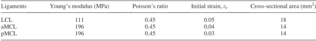
Similar to previous studies, the behavior of the ligaments was assumed linear elastic isotropic [25,29,30,36,37]. Each ligament was modeled as a beam with a specific cross-sectional area [29–31,36]. Furthermore, an initial preload, in agreement with previously validated numerical models, was set for each ligament [25,26,36]. The full overview of the properties of each ligament is illustrated in Table1.
The materials of the femoral component, tibial insert, and tibial tray were, respectively, cobalt–chromium alloy (CoCr), ultrahigh-molecular-weight-polyethylene (UHMWPE), and titanium alloy (Ti6Al4V). Similar to the previous bone model, the materials were assumed to be homogeneous, isotropic, and linear elastic
Fig. 1 Configurations analyzed, in terms of size and position for the augment (in darker grey) placed on the femoral compo-nent (a) and on the tibial component (b). M5medial; L5lateral.
[35,39]. The material properties, in terms of Young’s modulus and Poisson’s ratio, were as follows: CoCr:E¼220 GPa,¼0.3 [26,39]; UHMWPE: E¼685 MPa, ¼0.4 [26,37,40]; titanium: E¼110 GPa,¼0.3 [27]. For the UHMWPE, the yield strength and the ultimate tensile stress were, respectively, 22.3 MPa and 40.0 MPa [41].
A cement layer, with a constant penetration of 3 mm into the bone based on a test of different cementing techniques [42,43], was applied at the cut surface of the femur in contact with the femoral knee component and at the tibial bone cut in contact with the tibial component. The material adopted for the cement was homogeneous and isotropic withE¼2.62 GPa and¼0.3 [26,27,44].
The previous described properties were used for the conventional metal and for the bone cement, while porous metal (Trabecular Metal Material, Trabecular Metal Technology, Zimmer-Biomet, Warsaw, IN) was modeled as homogeneous, isotropic, and linear elastic with the following properties: E¼3.1 GPa,¼0.3 [45,46].
The coefficient of friction for the interaction between the femo-ral component and the tibial insert was set as 0.2 and between the bone and the implant was set to 0.6 [26,36,47]. A tie contact was considered for the interaction between the wedge and the implant.
Load and Boundary Conditions.Each configuration under-went the same load conditions. In detail, a vertical compression force of 2500 N applied along the femoral mechanical axis with the knee in full extension. This condition replicated the maximal knee axial force during gait corresponding to about 3.1 times an 80 kg body weight as already implemented in previous studies [25,26,36]. In such configuration, the patellar bone is not in con-tact with the femur and, therefore, his force was neglected. This finding was also experimentally measured, using instrumented knee, by Heinlein et al. [48]. In all the analyses, the tibial bone was distally fixed [25,26,36,37,39].
Finite Element Analysis.Each model was meshed using tetra-hedral elements with an approximate element size of 1 mm. A convergence test was performed to check the mesh quality. ABA-QUS/Standard version 2017 (Dassault Syste`mes, V
elizy-Villacoublay, France) was used to perform all the finite element simulations.
For all the defined models (control, femoral and tibial TKA components plus augments), the medial and lateral average von Mises bone stress was investigated. Two regions of interest were defined: one close to the augment (investigating a region with a depth of 10 mm) and the other one as a global region with a thick-ness of 50 mm (Fig.2). The region of interest close to the wedge was selected to check the potential localized effect of the augment to the bone (both on the medial and on the lateral sides), while the global region was analyzed to check if the augment was able to alter the bone stress distribution along the entire bone. The aver-age von Mises stress was compared among the different models and also with respect to the control model. For the three worst sce-nario cases, the von Mises stress was calculated in the 5 mm medial region in contact with the bone defect, as illustrated in Fig.2, and on the relative lateral side.
Results
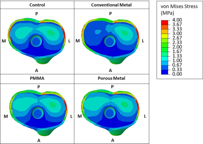
Figure3reports a graphical overview of the von Mises stress in the tibial-bone interface for all the considered materials in the
case of an augment of 5 mm. The configurations with bone cement and porous metal materials presented a similar distribution of the stress in the tibial bone compared to the control configuration (both in the medial and lateral sides). On the contrary, the use of a conventional metal augment (Titanium) led to a reduction of stress in the medial region of the tibial bone. This trend is also observed for the augment of 10 mm thickness.
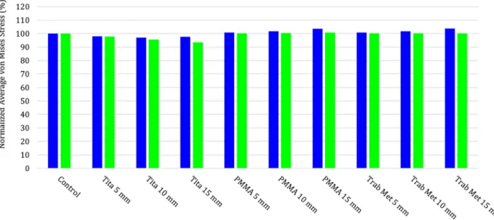
The quantitative values of the average bone von Mises stresses, in the medial and in the lateral side, in the control and for the other configurations in the case of proximal tibial augment, are reported in Fig.4(for local region of interest) and in Fig.5(for the global region of interest). Both figures present the values of the average von Mises stresses normalized with respect to the val-ues of the control configuration. Results show that an augment placed on the tibia produce an alteration of the bone stress mainly on the region close to the bone. PMMA and porous metal mainly influence the medial side of the bone, inducing a slight increase of the bone stress almost independent by the augment thickness and no effect on the lateral side. The alteration of the bone stress, with the use of these materials, is very limited in the global region of interest (average values variation less than 5%). The use of a tita-nium augment induces, in the region close to the augment, a decrease of the stress on the medial side up to 30%, almost free by the thickness of the augment. Moreover, a slight decrease of the average von Mises stress is also present in the lateral side (up to 10% for the augment of 15 mm). The use of a Titanium augment influences the tibial bone stress also globally, with a max decrease of the bone stress of 6.5% on the lateral side for the 15 mm augment.
Figure6reports a graphical overview of the superficial (corti-cal) von Mises stress in the femur for all the considered material models in the case of an augment of 5 mm placed distally. As highlighted by the dotted circle, the bone cement material and the porous metal material configurations presented a similar distribu-tion of the stress in the bone compared to the control configuradistribu-tion (both in the medial and lateral sides). In contrast, the use of a con-ventional metal (CoCr) augment led to a different stress distribu-tion in the femoral bone. This trend is also detected for the 10 mm augment.
In the case of distal femoral augments, the quantitative values of the average von Mises stresses on bone are reported in Fig.7 (for local region of interest) and in Fig.8(for the global region of interest), subgrouped for the medial and the lateral sides, in the control and all the other configurations.
The quantitative values of the average bone von Mises stresses, in the medial and in the lateral sides, in the control and for the other configurations in the case of posterior femoral augment, are reported in Fig.9(for local region of interest) and in Fig.10(for the global region of interest).
Also, in those figures, the values of the average von Mises stresses are normalized with respect to the values of the control configuration.
Once more, the presence of an augment induces an alteration in the bone stress. In the local region of interest, a distal femoral aug-ment (Fig.7) mainly influences the medial side (the one where the augment is placed), while the alteration on the lateral region is almost negligible (max variation 2.5%). Likewise, to the results identified for the tibia, the use of materials such as a bone cement or a porous metal presented a similar distribution of the medial stress, with a slight decrease of bone stress (around 5%) independ-ently by the augment thickness. The use of a conventional metal
Table 1 Material properties of the ligaments
Ligaments Young’s modulus (MPa) Poisson’s ratio Initial strain,er Cross-sectional area (mm2) LCL 111 0.45 0.05 18
aMCL 196 0.45 0.04 14 pMCL 196 0.45 0.03 14
(CoCr) augment led to a sensible decrease of stress in the medial femoral bone, up to 20% for an augment of 10 mm. However, the use of a distal femoral augment does not produce sensible altera-tion of the femoral stress in the global region of interest (Fig.8).
In the local region of interest, a posterior femoral augment (Fig.9) mainly influences the medial side (the same side of the augment), while the alteration on the lateral region is almost neg-ligible (max variation 2.5%) for PMMA and porous metal, but increases of 5% for the CoCr of 10 mm thickness. As observed before, the use of a bone cement material or of a porous metal material presented a similar distribution of the medial stress, with a slight decrease of bone stress (around 10%) independently by the augment thickness. The use of a conventional metal (CoCr) augment led to a sensible decrease of stress in the medial femoral bone, up to 20% for an augment of 10 mm. The use of a posterior femoral augment does not produce sensible alteration of the femo-ral stress in the global region of interest (Fig.10) for the PMMA and porous metal, the use of CoCr augment decreases the medial side (up to 10% for a thickness of 10 mm) but not the lateral side.
Figure11illustrates the results obtained in the local regions in the medial and lateral sides for the three worst case scenarios. As suggested, the absence of the wedge dramatically changes the stress distribution. For the tibial bone, an absence of the wedge mainly distributes the force laterally, increasing the stress up to 156%, and it reduces the stress medially, down to 71%. The lack of an augment in the femoral condyles acts differently, as the fem-oral bone is pushed against the femfem-oral component. In the case of a missing wedge, in the distal condyle, the stress distributions increase on both sides, up to 148% medially and up to 172% later-ally. This double increase is due to two different effects: the lat-eral side is more stressed (as in the case of the tibial bone defect) due to the missing wedge, while the medial side is still in contact
with the femoral component anteriorly and posteriorly (see Fig.2), thus generating peeks of stress that will increase the aver-age values compared with the control. Instead, a missing wedge in the posterior condyle has a slight effect on the regions of interest ana-lyzed as the load is still able to be spread by both condyles; mainly, we observed a slight reduction of the stress in the medial side (82%) and almost no effect on the lateral side (average stress 99%).
Discussion
The aim of this study was to quantify the change in bone stress induced by the use of an augment, combined with tibial or femoral TKA component to treat a bone defect. Different thicknesses, materials, and positions of the augment were investigated.
Bone stress and the relative load transferred to the bone are important factors that can be related to the life expectancy of each reconstructive technique. Ideally, stress–strain levels should be close to the control situation in which no augment is inserted [49]. As also reported by Patel et al. [50], the difference in elasticity between metal and bone may cause stress shielding and increase potential bone loss.
As usually happens in numerical studies, the present research presents some shortcomings. One limitation concerns with the use of geometries describing the different structures that are only based upon one anatomy; thus, any variation on the bone anatomy and bone deformities was considered at the moment. However, this approach is already largely used in modeling clinical situa-tions in the biomechanical research [24–27,39].
Another assumption covers the ligaments modeled as beams, as commonly used in literature, and in previously validated ligament model [25,29,51]. Moreover, the ligament was model as isotropic, even if the real behavior is more complicated [51]. A more
Fig. 2 Regions of interest analyzed for an augment of 5 mm: (a) medial local region of interest of the tibia, (b) lateral local region of interest of the tibia, (c) medial global region of interest of the tibia, (d) lateral global region of interest of the tibia, (e) medial local region of interest of the femur (distal wedge), (b) lateral local region of interest of the femur (distal wedge), and (g) medial and lateral local regions of interest of the femur (posterior wedge)
realistic modeling of the ligament could have been integrated in the study but, as the joint line was never changed and therefore the ligament length (and therefore strain) was constant among the different configurations [25,52,53], such modelization was not
implemented in the study. Additionally, perfectly shaped struc-tural graft is considered in full contact with host bone. In a vivo situation, these conditions might not occur, which may change the load share and implant stability [49].
Fig. 3 Graphical overview of the von Mises stress in the tibial-bone interface for all the considered material models in the case of an augment of 5 mm. A5anterior; P5posterior; M5medial; L5lateral.
Fig. 4 Medial and lateral average bone von Mises stresses in the control and for the other configurations, in the case of proxi-mal tibial augment, in the region of interest close to the augment (10 mm depth). The values of the average von Mises stresses are normalized with respect to the values of the control configuration.
The material models of the different analyzed structures integrated several assumptions, approximating their natural behavior. In fact, the material properties of the bony structures as well as the soft tissues were assumed linear elastic and homo-geneous, even if, as it is well known, the cortical as well as the cancellous bones contain spatial inhomogeneity in their properties [35].
In this study, the analysis is restricted to a medial bone defect because several authors reported as the most frequent [54–59]; however, in clinical practice, it is possible that a patient may pres-ent additional defects, such as cpres-entral defects at the time of sur-gery. Such configurations have not been yet modeled; thus, the findings of this research cannot cover all the clinical situations of patients receiving this treatment.
Fig. 5 Medial and lateral average bone von Mises stresses in the control and for the other configurations, in the case of proxi-mal tibial augment, in the global region of interest (50 mm depth). The values of the average von Mises stresses are norproxi-malized with respect to the values of the control configuration.
Fig. 6 Graphical overview of the von Mises stress in the femoral-bone interface for all the considered material models, in the medial, lateral, and posterior views, in the case of an augment of 5 mm placed distally. For the control, the following labels were added: A5anterior; P5posterior; M5medial; L5lateral. The dotted oval in the medial view highlights the region that shows the main changes in the surface stress.
Despite these limitations, our results are in agreement with the results presented in the literature for the bone stress change after the insertion of tibial augment [49,54,56]. Completo et al. [49] found a reduction of the stress in the tibial bone of around 20% when a metal augment was used and a change less than % when a cement wedge was used. Fehring et al. [56], analyzing proximal tibial defect in primary and revision arthroplasty, identify a marked change in the medial side with respect to the lateral side.
This study shows that a metal augment could alter the bone stress and this is aligned with clinical findings [15,20,57–59] in which the high rate of radiolucent lines just beneath the metal has often been pointed out as a shortcoming of metal augment.
Pagnano et al. [58] reported radiolucent lines between wedge-type augmentation cement and bone in 13 of 24 knees with an average radiographic follow-up period of 4.8 years. Brand et al. [57] reported that 6 of 22 knees had radiolucent lines beneath the metal wedge at an average follow-up of 3.1 years. Tsukada et al. [59] retrospectively identify that the clinical results of total knee arthroplasty with metal augmentation were not inferior to those in patients without bone defects. However, radiolucent lines were observed in 30.3%.
Indeed, the presence of a wedge is a fundamental tool to treat bone defect, because, if it is untreated, it could lead to a missing mechanical support producing high bone stress variation.
Fig. 7 Medial and lateral average bone von Mises stresses in the control and for the other configurations, in the case of distal femoral augment, in the region of interest close to the augment (10 mm depth). The values of the average von Mises stresses are normalized with respect to the values of the control configuration.
Fig. 8 Medial and lateral average bone von Mises stresses in the control and for the other configurations, in the case of distal femoral augment, in the global region of interest (50 mm depth). The values of the average von Mises stresses are normalized with respect to the values of the control configuration.
However, among the different augment options, the main parame-ter that is responsible of the change of bone stress is the maparame-terial (due to its stiffness) of the augment that should be as close as possible to the one of the bone. In detail, the presence of no-porous metal in the tibial augment can change the bone stress (up to 19%) while the use of bone cement of porous tantalum metal can reduce the change in stress (less than 5%) that might result in a substantially lower loosening rate. Moreover, due to the additional benefit of the porous metal of allowing bone ingrowth, the loosening rate will be further reduced; however, the osteointegration phenomenon was not modeled in the present study.
Metal (both titanium and CoCr) has the least satisfying results inducing the highest change in bone stress with respect to the control.
Bone cement has the best results in terms of bone stress; how-ever, it is only suitable for extremely small defects. As example, Cuckler [6] stated that bone cement can be used conveniently to fill the defects with size<10 mm. If the defect appears to be larger than 10 mm in its largest dimension, then a need for augmentation or bone grafting should be anticipated.
Porous tantalum trabecular metal has results very close to cement and it could be considered as a good alternative to cement for any size of defect.
Fig. 9 Medial and lateral average bone von Mises stresses in the control and for the other configurations, in the case of pos-terior femoral augment, in the region of interest close to the augment (10 mm depth). The values of the average von Mises stresses are normalized with respect to the values of the control configuration.
Fig. 10 Medial and lateral average bone von Mises stresses in the control and for the other configurations, in the case of pos-terior femoral augment, in the global region of interest (50 mm depth). The values of the average von Mises stresses are nor-malized with respect to the values of the control configuration.
Conclusions
The results of this study show that the presence of an augment helps in treat bone defect; however, it always alters the bone stress in the region close to the augment. The thickness of the augment did not result in significant change of bone stress while a change in material have a sensible influence on the bone stress. The change in stress is more marked when a conventional metal is used. Porous metal and bone cement will reduce the change in stress that might result in a substantially lower loosening rate. This is due to a change in the stiffness of the material used for the augment. For allowing a decrease of the pick of stress between the implant-bone interface, the stiffness of the augment should be as close as possible to one of the bone. As conventional metals show the least satisfying results and cement is clinically suitable only for extremely small defects, porous metal shows to be a good alternative to cement for any size of defect.
Acknowledgment
This work was supported by FNRS (Fonds National de la Recherche Scientifique, CDR 19545501) and by FER ULB (Fonds d’Encouragementa la Recherche, FER 2014). The funders had no role in study design, data collection and analysis, decision to pub-lish, or preparation of the manuscript. The author would also like to thank Daniele Vignoni and Olivier Argiolas for their contribu-tions and assistance on this study.
Funding Data
Fonds De La Recherche Scientifique—FNRS (CDR 1954550).
Universite Libre De Bruxelles (FER 2014).
References
[1] Bozic, K. J., Kurtz, S. M., Lau, E., Ong, K., Chiu, V., Vail, T. P., Rubash, H. E., and Berry, D. J., 2010, “The Epidemiology of Revision Total Knee Arthro-plasty in the United States,”Clin. Orthop. Relat. Res.,468(1), pp. 5–51. [2] Sheng, P. Y., Konttinen, L., Lehto, M., Ogino, D., Jamsen, E., Nevalainen, J.,
Pajam€aki, J., Halonen, P., and Konttinen, Y. T., 2006, “Revision Total Knee
Arthroplasty: 1990 Through 2002. A Review of the Finnish Arthroplasty Regis-try,”J. Bone Jt. Surg. Am.,88(7), pp. 1425–1430.
[3] Whiteside, L. A., 2003, “Cementless Revision Total Knee Arthroplasty,”The Adult Knee, J. J. Callaghan, A. G. Rosenberg, H. E. Rubash, P. T. Simonian, and T. L. Wickiewicz, eds., Lippincott-Williams & Wilkins, Philadelphia, PA, pp. 1465–1472.
[4] Whittaker, J. P., Dharmarajan, R., and Toms, A. D., 2008, “The Management of Bone Loss in Revision Total Knee Replacement,”J. Bone Jt. Surg. Br.,90(8), pp. 981–987.
[5] Huten, D., 2013, “Femorotibial Bone Loss During Revision Total Knee Arthroplasty,”Orthop. Traumatol. Surg. Res.,99S(1), pp. S22–S33.
[6] Cuckler, J. M., 2004, “Bone Loss in Total Knee Arthroplasty: Graft Augment and Options,”J Arthroplasty,19(4 Suppl. 1), pp. 56–58.
[7] Radnay, C. S., and Scuderi, G. R., 2006, “Management of Bone Loss: Aug-ments, Cones, Offset Stems,”Clin. Orthop.,446, pp. 83–92.
[8] Altchek, D., Sculco, T. P., and Rawlins, B., 1989, “Autogenous Bone Grafting for Severe Angular Deformity in Total Knee Arthroplasty,”J Arthroplasty, 4(2), pp. 151–155.
[9] Insall, J. N., 2006, “Surgical Techniques and Instrumentation in Total Knee Arthroplasty,”Surgery of the Knee, J. N. Insall, ed., 4th ed., Churchill Living-stone, New York, p. 1455.
[10] Fehring, T. K., Christie, M. J., Lavernia, C., Mason, J. B., McAuley, J. P., Mac-Donald, S. J., and Springer, B. D., 2008, “Revision Total Knee Arthroplasty: Planning, Management, and Controversies,” Instr. Course Lect.,57, pp. 341–363. [11] Munjal, S., Phillips, M. J., and Krackow, K. A., 2001, “Revision Total Knee Arthroplasty: Planning, Controversies, and Management—Infection,” Instr. Course Lect.,50, pp. 367–377.
[12] Clarke, H. D., and Scuderi, G. R., 2001, “Revision Total Knee Arthroplasty: Planning, Management, Controversies, and Surgical Approaches,” Instr. Course Lect.,50, pp. 359–365.
[13] Completo, A., Simoes, J. A., and Fonseca, F., 2009, “Revision Total Knee Arthroplasty: The Influence of Femoral Stems in Load Sharing and Stability,” Knee,16(4), pp. 275–279.
[14] Yi, Y. Q., Chun, H. Y., Kwong, Y. C., and Fu, Y. N., 2012, “Review Article: Treatments for Bone Loss in Revision Total Knee Arthroplasty,”J. Orthop. Surg.,20(1), pp. 78–86.
[15] Lee, J. K., and Choi, C. H., 2011, “Management of Tibial Bone Defects With Metal Augmentation in Primary Total Knee Replacement,”J. Bone Jt. Surg. Br.,93(11), pp. 1493–6.
[16] Mountney, J., Wilson, D. R., Paice, M., Masri, B. A., and Greidanus, N. V., 2008, “The Effect of an Augmentation Patella Prosthesis Versus Patelloplasty on Revision Patellar Kinematics and Quadriceps Tendon Force: An Ex Vivo Study,”J. Arthroplasty,23(8), pp. 1219–1231.
[17] Completo, A., Simoes, J. A., Fonseca, F., and Oliveira, M., 2008, “The Influ-ence of Different Tibial Stem Designs in Load Sharing and Stability at the Cement-Bone Interface in Revision TKA,”Knee,15(3), pp. 227–232. [18] Saragaglia, D., Estour, G., Nemer, C., and Colle, P. E., 2009, “Revision of 33
Unicompartmental Knee Prostheses Using Total Knee Arthroplasty: Strategy and Results,”Int. Orthop.,33(4), pp. 969–974.
[19] Parvizi, J., Marrs, J., and Morrey, B. F., 2003, “Total Knee Arthroplasty for Neuropathic (Charcot) Joints,”Clin. Orthop. Relat. Res.,416, pp. 145–150.
Fig. 11 Medial and lateral average bone von Mises stresses for the three worst case scenarios analyzed. Tibial configuration: no wedge on the medial tibial side. Femoral distal configuration: no distal wedge on the medial femoral condyle. Femoral pos-terior configuration: no pospos-terior wedge on the medial femoral condyle. In the three cases, the bone defect has a thickness of 5 mm. The normalized average von Mises stress is calculated in the 5 mm medial region in contact with the defect, as illus-trated in Fig.2, and on the relative lateral side.
[20] Rand, J. A., 2003, “Treatment of the Patella at Reimplantation for Septic Total Knee Arthroplasty,”Clin. Orthop. Relat. Res.,416, pp. 105–109.
[21] van Loon, C. J., de Waal Malefijt, M. C., Buma, P., Stolk, T., Verdonschot, N., Tromp, A. M., Huiskes, R., and Barneveld, A., 2000, “Autologous Morsellised Bone Grafting Restores Uncontained Femoral Bone Defects in Knee Arthro-plasty, An Vivo Study Horses,”J. Bone Jt. Surg. Br.,82(3), pp. 436–444. [22] van Loon, C. J., de Waal Malefijt, M. C., Verdonschot, N., Buma, P., van der
Aa, A. J., and Huiskes, R., 1999, “Morsellized Bone Grafting Compensates for Femoral Bone Loss in Revision Total Knee Arthroplasty. An Experimental Study,”Biomaterials,20(1), pp. 85–89.
[23] Stuchin, S. A., 1993, “Allografting in Total Knee Replacement Arthroplasty,” Semin. Arthroplasty,4(2), pp. 117–122.
[24] Pianigiani, S., and Innocenti, B., 2015, “The Use of Finite Element Modeling to Improve Biomechanical Research on Knee Prosthesis,”New Developments in Knee Prosthesis Research, J, . Stewart, eds., Nova Science Publishers, Hauppauge, NY, pp. 113–126.
[25] Innocenti, B., Bilgen, O. F., Labey, L., van Lenthe, G. H., Vender Sloten, J., and Catani, F., 2014, “Load Sharing and Ligament Strains in Balanced, Over-stuffed and UnderOver-stuffed UKA. A Validated Finite Element Analysis,” J. Arthroplasty,29(7), pp. 1491–1498.
[26] Innocenti, B., Bellemans, J., and Catani, F., 2015, “Deviations From Optimal Alignment in TKA: Is There a Biomechanical Difference Between Femoral or Tibial Component Alignment?,”J. Arthroplasty,31(1), pp. 295–301. [27] Soenen, M., Baracchi, M., De Corte, R., Labey, L., and Innocenti, B., 2013,
“Stemmed TKA in a Femur With a Total Hip Arthroplasty. Is There a Safe Dis-tance Between the Stem Tips?,”J. Arthroplasty,28(8), p. 1437.
[28] Victor, J., Van Doninck, D., Labey, L., Innocenti, B., Parizel, P. M., and Belle-mans, J., 2009, “How Precise Can Bony Landmarks Be Determined on a CT Scan of the Knee?,”Knee,16(5), p. 358.
[29] Innocenti, B., Pianigiani, S., Labey, L., Victor, J., and Bellemans, J., 2011, “Contact Forces in Several TKA Designs During Squatting: A Numerical Sensi-tivity Analysis,”J. Biomech.,44(8), pp. 1573–1581.
[30] Pianigiani, S., Chevalier, Y., Labey, L., Pascale, V., and Innocenti, B., 2012, “Tibio-Femoral Kinematics in Different Total Knee Arthroplasty Designs Dur-ing a Loaded Squat: A Numerical Sensitivity Study,”J. Biomech.,45(13), pp. 2315–2323.
[31] Pianigiani, S., Labey, L., Pascale, W., and Innocenti, B., 2016, “Knee Kinetics and Kinematics: What Are the Effects of TKA Malconfigurations?,” Knee Surg., Sports Traumatol., Arthrosc.,24(8), pp. 2415–2421.
[32] Innocenti, B., Robledo, H., Bernabe, R., and Pianigiani, S., 2015, “Investigation on the Effects Induced by TKA Features on Tibio-Femoral Mechanics. Part I: Femoral Component Designs,”J. Mech. Med. Biol.,15(2), p. 1540034. [33] Paratte, S., Pagnano, M. W., Trousdale, R. T., Berry, D. J., 2010, “Effect of
Post-operative Mechanical Axis Alignment on the Fifteen-Year Survival of Modern, Cemented Total Knee Replacements,”J. Bone Jt. Surg. Am.,15(12), p. 2143. [34] Ingrassia, T., Nalbone, L., Nigrelli, V., Tumino, V., and Ricotta, V., 2013,
“Finite Element Analysis of Two Total Knee Prostheses,”Int. J. Interact. Des. Manuf.,7(2), p. 91.
[35] Sarathi Kopparti, P., and Lewis, G., 2007, “Influence of Three Variables on the Stresses in a Three-dimensional Model of a Proximal Tibia-Total Knee Implant Construct,” Biomed. Mater. Eng.,17, p. 19.
[36] Innocenti, B., Pianigiani, S., Ramundo, G., and Thienpont, E., 2017, “Biomechanical Effects of Different Varus and Valgus Alignments in Medial Unicompartmental Knee Arthroplasty,”J. Arthroplasty,31(12), pp. 2685–2691. [37] Brihault, J., Navacchia, A., Pianigiani, S., Labey, L., De Corte, R., Pascale, V., and Innocenti, B., 2016, “All-Polyethylene Tibial Components Generate Higher Stress and Micromotions Than Metal-Backed Tibial Components in Total Knee Arthroplasty,”Knee Surg. Sports Traumatol. Arthrosc.,24(8), pp. 2550–2559. [38] Kayabasi, O., and Ekici, B., 2007, “The Effects of Static, Dynamic and Fatigue
Behavior on Three-dimensional Shape Optimization of Hip Prosthesis by Finite Element Method,”Mater. Des.,28(8), p. 2269.
[39] Innocenti, B., Truyens, E., Labey, L., Wong, P., Victor, J., and Bellemans, J., 2009, “Can Medio-Lateral Baseplate Position and Load Sharing Induce Asymp-tomatic Local Bone Resorption on the Proximal Tibia? A Finite Element Study,”J. Orthop. Surg. Res.,4(1), p. 26.
[40] Catani, F., Innocenti, B., Belvedere, C., Labey, L., Ensini, A., and Leardini, A., 2010, “The Mark Coventry Award: Articular Contact Estimation in TKA Using
In Vivo Kinematics and Finite Element Analysis,”Clin. Orthop. Relat. Res., 468(4), p. 19.
[41] Arnout, N., Vanlommel, L., Vanlommel, J., Luyckx, J. P., Labey, L., Innocenti, B., Victor, J., and Bellemans, J., 2015, “Post-Cam Mechanics and Tibiofemoral Kinematics: A Dynamic In Vitro Analysis of Eight Posterior-Stabilized Total Knee Designs,”Knee Surg. Sports Traumatol. Arthrosc.,23(11), p. 3343. [42] Vaninbroukx, M., Labey, L., Innocenti, B., and Bellemans, J., 2009,
“Cementing the Femoral Component in Total Arthroplasty: Which Technique Is the Best?,”Knee,16(4), p. 265.
[43] Vanlommel, J., Luyckx, J. P., Labey, L., Innocenti, B., De Corte, R., and Belle-mans, J., 2001, “Cementing the Tibial Component in Total Knee Arthroplasty: Which Technique Is the Best?,”J. Arthroplasty,26(3), p. 492.
[44] Waanders, D., Janssen, D., Mann, A. K., 2010, “The Mechanical Effects of Different Levels of Cement Penetration at the Cement–Bone Interface,”J. Bio-mech.,43(6), p. 1167.
[45] Medlin, D. J., Charlebois, S., Swarts, D., Shetty, R., and Poggie, R. A., “Metallurgical Characterization of a Porous Tantalum Biomaterial (Trabecular MetalTM) for Orthopaedic Implant Applications,” Medical Device Materials: Materials & Processes for Medical Devices Conference, pp. 394–398. [46] Rawlinson, J. J., Wright, T. M., and Bartel, D. L., 2005, “FEA of a Porous
Tan-talum Monoblock Tibia Compared With a Metal-Backed Tibial Component,” 51st Annual Meeting of the Orthopaedic Research Society, Washington, DC, Paper No:0165.
[47] El-Zayat, B. F., Heyse, T. J., Fanciullacci, N., Labey, L., Fuchs-Winkelmann, S., and Innocenti, B., 2016, “Fixation Techniques and Stem Dimensions in Hinged Total Knee Arthroplasty: A Finite Element Study,”Arch. Orthop. Traum. Surg.,136(12), pp. 1741–1752.
[48] Heinlein, B., Kutzner, I., Graichen, F., Bender, A., Rohlmann, A., Halder, M. A., Beier, A., and Bergmann, G., 2009, “Direct Comparison of Measured and Calculated Total Knee Replacement Force Envelopes During Walking in the Presence of Normal and Abnormal Gait Patterns,”J. Biomech.,45(6), pp. 990–996.
[49] Completo, A., Duarte, R., Fonseca, F., Sim~oes, J. A., Ramos, A., and Relvas, C., 2013, “Biomechanical Evaluation of Different Reconstructive Techniques of Proximal Tibia in Revision Total Knee Arthroplasty: An in-Vitro and Finite Element Analysis,”Clin. Biomech.,28(3), pp. 291–298.
[50] Patel, J. V., Masonis, J. L., Guerin, J., Bourne, R. B., and Rorabeck, C. H., 2004, “The Fate of Augments to Treat Type-2 Bone Defects in Revision Knee Arthroplasty,”J. Bone Jt. Surg. Br.,86(2), pp. 195–199.
[51] Galbusera, F., Freutel, M., D€urselen, L., D’Aiuto, M., Croce, D., Villa, T., San-sone, V., and Innocenti, B., 2014, “Material Models and Properties in the Finite Element Analysis of Knee Ligaments: A Literature Review,”Front Bioeng. Biotechnol.,2, p. 54.
[52] Delport, H., Labey, L., De Corte, R., Innocenti, B., Vander Sloten, J., and Belle-mans, J., 2013, “Collateral Ligament Strains During Knee Joint Laxity Evalua-tion Before and After TKA,”Clin. Biomech.,28(7), pp. 777–782.
[53] Delport, H., Labey, L., Innocenti, B., De Corte, R., Vander Sloten, J., and Belle-mans, J., 2015, “Restoration of Constitutional Alignment in TKA Leads to More Physiological Strains in the Collateral Ligaments,”KSSTA J.,23(8), pp. 2159–2169.
[54] Rand, J. A., 1991, “Bone Deficiency in Total Knee Arthroplasty: Use of Metal Wedge Augmentation,” Clin. Orthop.,271, p. 63.
[55] Mason, J. B., and Scott, R. D., 1999, “Management of Severe Bone Loss. Pros-thetic Modularity and Custom Implants,”Revision Total Knee Arthroplasty, P. A. Lotke, and J. P. Garino, eds., Lippincott-Raven, Philadelphia, PA, p. 207. [56] Fehring, T. K., Peindl, R. D., Humble, R. S., Harrow, M. E., and Frick, S. L.,
1996, “Modular Tibial Augmentations in Total Knee Arthroplasty,” Clin. Orthop.,327, p. 207.
[57] Brand, M. G., Daley, R. J., Ewald, F. C., and Scott, R. D., 1989, “Tibial Tray Augmentation With Modular Metal Wedges for Tibial Bone Stock Deficiency,” Clin. Orthop. Relat. Res.,248, pp. 71–79.
[58] Pagnano, M. W., Trousdale, R. T., and Rand, J. A., 1995, “Tibial Wedge Aug-mentation for Bone Deficiency in Total Knee Arthroplasty: A Follow-up Study,”Clin. Orthop. Relat. Res.,321, pp. 151–155.
[59] Tsukada, S., Wakui, M., and Matsueda, M., 2013, “Metal Block Augmentation for Bone Defects of the Medial Tibia During Primary Total Knee Arthroplasty,” J. Orthop. Surg. Res.,8(1), p. 36.