i FINAL PROJECT (RC14-1501)
INFLUENCE OF BENTONITE AND BLAST FURNACE
SLAG TO THE SELF HEALING BEHAVIOUR OF
CRACKED CEMENT PASTE
M. SAMSUL ANAM NRP. 31 11 100 076
Supervisor :
Dr.Eng. Januarti Jaya Ekaputri, ST. MT. Prof. Dr. Ir. Triwulan, DEA.
i TITLE PAGE
FINAL PROJECT (RC14-1501)
INFLUENCE OF BENTONITE AND BLAST FURNACE
SLAG TO THE SELF HEALING BEHAVIOUR OF
CRACKED CEMENT PASTE
M. SAMSUL ANAM NRP. 31 11 100 076
Supervisor :
Dr.Eng. Januarti Jaya Ekaputri, ST. MT. Prof. Dr. Ir. Triwulan, DEA.
APPROVAL SHEET
v
INFLUENCE OF BENTONITE AND BLAST FURNACE SLAG TO THE SELF HEALING BEHAVIOUR OF CRACKED
CEMENT PASTE
Student Name : M. Samsul Anam
NRP : 31 11 100 076
Departement : Civil Engineering Department FTSP – ITS
Supervisor : Dr. Eng. Januarti J. E., ST. MT.
Prof. Dr. Ir. Triwulan, DEA.
ABSTRACT
Cracks, caused by shrinkage and external loading faciliates the ingress of aggressive and harmful substance into concrete and reduce the durability of the structures. It is well known that self – healing of cracks can significantly improve the durability of the concrete structure. In this reseach, self healing propertis of the cement paste containing bentonite and blast furnace slag were studied. The self healing properties were evaluated by using 4 parameters, including surface crack width (βindex), crack depth (αindex), tensile strength recovery, and flexural stiffness recovery. In combination with microscopic obervation, a healing process over time was drawn. The result show that bentonite can improve healing properties, in term of surface crack width and crack depth. In the other hand BFS also could also improve self healing properties, in terms of crack depth, direst tensile regain, and flexural stiffnes. Carbonation reaction still to be main mechanism which contribute self healing process, althought continued hydration still occure.
vii
PREFACE
Thank to Almighty God who has given His favor to the author for finishing the research and completing the final project report entitled ""Influence of bentonite and blast furnace slag to the self-healing behavior in cracked cement paste". This research describe a solution to improve durability of the concrete structures which is due to a cracks in the concrete materials, by applying self-healing concrete approach. Since the durability is very important factor which is related to the age of buildings, the self-healing concrete is very important to develope. This reasearch focus on the influence of bentonite and blast furnace slag to the self-healing behaviour which is evaluated by using 6 parameters, i.e crack width, crack depth, tensile strength recovery, flexural stiffness recovery, pH, mineral closing crack, and cloride ion penetration to analyze the durability of the cracked cement paste. That 6 parameters are discused, both influence of each material and relationship between each parameter to the self-healing behaviour.
This research has been done for 8 months, which is started from March 2015 and fisnished on January 2016. Several testing, measurement, analysis and observation have been conducted in Laboratory of Concrete and Buiding Materials ITS, Cement Reseacrh Center PT. Semen Indonesia, Laboratory of Analysis and Instrumentation (Lab. TAKI) ITS, and Laboratory of Enviroment Quality ITS. Furthermore, the author likewise wish to express his profound and earnest appreciation for the individuals who have supported, guided and helped in finishing this research report, i.e :
1. The author’s beloved Parents, Supriyadi and Partutik. The author would like to thanks so much for their prayer, support, affection, advices, guidance, and help in all my life, their love is beyond any words.
viii
correlation, advice, and suggestion which are very helpful in finishing this report. The author would like to thanks for for her time to share her great knowledge and great experiences to the author.
3. Prof. Dr. Ir. Triwulan, DEA as second supervisor, who has guided me with his worthy, valuable guidance, encouragement, patient, correlation, advice, suggestion and correction to improve the quality of this report. The author would like to thanks for for her time to share her great knowledge and great experiences to the author
4. Trieddy Susanto, ST, MT as external supervisor from PT. Semen Indonesia. The author would like to thanks for his guidance, advice, suggestion, and correction to improve the quality of this report.
5. Mr. Basar, Mr. Hardjo, Mr. Totok, Mr. Supri, Mr. Ji as laboran in Laboratory of Concrete and Buidling Materials for their support and favor in conducting some testing and measurement of this reaseach.
6. The author’s Lab-mate, i.e Wawan, Alex, Novema, Luthfi Anas, James, Nizar, Ziad, Adi, Achsan, Henry, Kefi, Ila, Ruceh, Annisa, Inne, Like, Kiky, and Wuri, who have given beatiful and unforgettable memories as long as the author conducted his research in the Laboratory of Concrete and Building Materials.
7. All lecturers of Civil Engineering Department ITS, who have transferred much knowledge to the author which very helpful in finishing final project report. The author would like to thanks for guidance, instruction and help during study at the Civil Engineering Departement
8. The author’s beloved friends in Civil Engineering Department’11 and S54. The author would like to thanks for togetherness and attention as long as the author study in Civil Engineering Departement ITS.
ix
10. Minister of Research and Higher Education which has fund the Financial support for this research work.
11. PT. PT. Semen Indonesia for supporting cement materials, blast furnace slag, and supporting some experimen. 12. PT. Surya Beton Indonesia and PT. Varia Usaha Beton for
supporting cement materials.
The last, this final project report is far from being perfect, but it is expected that this report will be useful not only for the researcher, but also the readers. For this reason, constructive thought full suggestions and critics are well come to make this report better.
. Surabaya, January 25, 2016 Author
xi
CHAPTER I INTRODUCTION ... 1
1.1. Background ... 1
1.2. Research Problems ... 4
1.3. Research Boundaries ... 5
1.4. Research Objective... 5
1.5. Benefits ... 6
CHAPTER II LITERATURE REVIEW ... 7
2.1. Crack on the Concrete Structures ... 7
2.2. Conditions for Self-Healing ... 8
2.3. Self-Healing Mechanism ... 9
2.4. Self-Healing Mechanism with Continued Hydration ... 11
2.5. The influence of Pozzoland to Ca(OH)2 content ... 13
2.6. Characteristics of Bentonite Clay ... 14
2.7. Chemical Structure of Montmorolinite ... 16
2.8. Autogenous Healing Concrete using Geomaterial ... 18
2.9. Blast Furnace Slag as Autogenous Healing material ... 23
CHAPTER III RESEARCH METHODOLOGY ... 35
3.1. Literature Riview ... 36
3.2. Preparation of Materials ... 37
3.3. Analisys of Raw Materials Properties ... 37
3.3.1. Method to Determine Specific Gravity ... 37
3.3.2. Method to Determine Density ... 39
xii
3.3.4. Flow Table Test ... 44
3.3.5. Particles Size Analyze ... 45
3.3.6. X-Ray Fluoroscene ... 46
3.3.7. X-Ray Diffraction ... 46
3.4. Mix Proportion Series ... 47
3.8. Introducing Artificial Crack ... 53
3.9. Water Imersion Curing ... 54
3.10.Self Healing Evaluation ... 54
3.10.1. Ultrasonic Pulse Velocity Testing ... 54
3.10.2. Microscopic Investigation ... 57
3.10.3. Four Point Bending Test ... 62
5.10.4. Direct Tensile Strenght Test ... 63
5.10.5. Measuring pH of Specimens ... 65
5.10.6. Cloride Ion Penetration Test ... 67
5.10.7. XRD Analysis ... 69
CHAPTER IV RESULTS AND DISCUSSIONS ... 71
4.1. General Introduction ... 71
4.2. Testing Result of The Raw Materials ... 71
4.2.1. Spesific Gravity of Material ... 71
4.2.2. Density of Material ... 73
4.2.3. Strenght Activity Index ... 75
4.2.4. XRD ... 78
4.2.5. XRF ... 82
4.2.6. Particles Size Distribution ... 84
4.2.7. Spesific Surface Area (SSA) ... 86
4.2.8. Flowability of The Cement Paste Mixture ... 87
xiii
4.3.1. Crack Width ... 92
4.3.2. Crack Depth ... 107
4.3.3. Direct Tensile Regain ... 113
4.3.5. Alkalinity ... 127
4.3.6. XRD ... 130
4.4. Discussions ... 138
4.4.1. Influence of Bentonite to the Self Healing ... 138
4.4.2. Influence of BFS to the Self Healing ... 139
4.4.3. Correlation between w/c and healing ability ... 140
4.4.4. Flexural - Tensile Strenght Relationships ... 142
CHAPTER V CONCLUSIONS... 143
xv
LIST OF FIGURES
Figure 2. 1. Maximum crack width (functions of water pressure (h/d) according to Lohmeyer and Meichsner) ... 9 Figure 2. 2. Causes of autogeneous self-healing ... 10 Figure 2. 3. Model for calculating the self-healing mechanism
based on continued hydration ... 12 Figure 2. 4. Ca (OH)2 content based on cement type and
additional pozzoland material ... 14 Figure 2. 5. Chemical structure of Montmorollonite ... 17 Figure 2. 6. Self-healing [OPC90٪+CSA5٪+Geo 5٪] ... 19 Figure 2. 7. A comparison X-Ray mapping between self healing
zone and original zone ... 19 Figure 2. 8. A comparison geopolimer gell in the self-healing
zone with Hydrogarnet in original zone ... 20 Figure 2. 9. Permeability Coefficient of Specimen using some
mineral adimixture ... 21 Figure 2. 10. γ Index value of Specimen using some mineral
adimixture ... 22 Figure 2. 11. Flexural strength of cracked concrete using
nanoclay for different curing conditions and
precracking time ... 23 Figure 2. 12. Crack self-closing ratio ... 24 Figure 2. 13. Cumulative heat production Q [J/g] for the different
mixtures under investigation ... 25 Figure 2. 14. Influence of carbonation degrees to the fillliing
fraction of crack ... 26 Figure 2. 15. Faction minerals which close the crack ... 27 Figure 2. 16. Influence of BFS replacement to Flexural strength
concrete after cracking ... 28 Figure 2. 17. Influence of BFS replacement to Splitting tensile
strength concrete after cracking ... 28 Figure 2. 18. Influence of BFS replacement to compresif strength
xvi
Figure 2. 19. Maximum crack width for 100% healing ... 30
Figure 2. 20. Crack healing percentage as a function of the initial crack width for A) fresh water and B) sea water ... 31
Figure 2. 21. Chloride ion permeability of ECC mixtures using slag due to repetitive preloading ... 32
Figure 2. 22. Total crack closure rates of ECC mixtures with slag specimens due to self healing ... 33
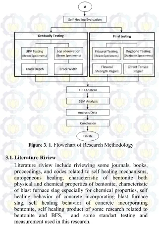
Figure 3. 1. Flowchart of Research Methodology ... 36
Figure 3. 2. Measuring flow diamater of cement paste ... 45
Figure 3. 3. Explanation of Sample Code ... 47
Figure 3. 4. Detail specification of briquet ... 48
Figure 3. 5. Dimension of Beam specimens ... 49
Figure 3. 6. Crack initiation by indtroducing teflon sheet as depth as 5 mm ... 49
Figure 3. 7. Detail of steel reinforcement ... 49
Figure 3. 8. Cylinder specimens ... 50
Figure 3. 9. Coated specimens, a) cover side b) top side ... 50
Figure 3. 10. Curing by covering specimens with wet burlap .... 52
Figure 3. 11. Introducing artificial crack, a) Cylinder specimens by using splitting test, b) beam specimens by using four point bending test ... 53
Figure 3. 12. a ) Introducing artificial crack of dogbone specimens by using tensile test, b) dogbone specimens are holded by using dogbone specimen holder ... 53
Figure 3. 13. Water Imersion Curing ... 54
Figure 3. 14. Schematic of Pulse Velocity Apparatus ... 55
Figure 3. 15. Transmitter and receiver position for UPV measurement ... 56
Figure 3. 16. Typical arrangement for Measuring Crack Depth 57 Figure 3. 17. Example crack width graphic for calculating healing efficiency index ... 59
Figure 3. 18. Determine crack position ... 59
Figure 3. 19. Choosing line button ... 60
xvii
Figure 3. 21. Showing crack width data ... 60
Figure 3. 22 Determine crack position ... 61
Figure 3. 23. Drawing poligon line ... 61
Figure 3. 24. Typical arrangement for Four Point Bending Test 63 Figure 3. 25. Typical arrangement for direct tensile test according to CRD-C 260-01 ... 64
Figure 3. 26. a) Cylinder Specimens for cloride penetration, b) Top Side, c) bottom side ... 67
Figure 3. 27. a) NaCl Flake, b) Dissolving NaCl flake in the water ... 68
Figure 3. 28. a) Solution for Cloride penetration, b) Specimens were submerged in NaCl solution ... 68
Figure 3. 29. . Sampling for Cloride Ion Penetration Specimens 69 Figure 4. 1. SAI of OPC, Ca-Bentonite and BFS ... 77
Figure 4. 2. Diffractogram of BFS ... 80
Figure 4. 3. Diffractogram of Bentonite ... 81
Figure 4. 4. Particle Size Distribution of Bentonite ... 84
Figure 4. 5. Cummulative Particle Size of Bentonite... 85
Figure 4. 6. Particle Size Distribution of BFS ... 85
Figure 4. 7. Cummulative Particle Size of BFS ... 86
Figure 4. 8. Flowability of the cement paste mixture ... 89
Figure 4. 9. SEM image of BFS ... 90
Figure 4. 10. Method to determine w/b for each mixture ... 91
Figure 4. 11.Position of crack measurement point ... 93
Figure 4. 12. Evolution of the surface crack width over time for initial crack width 0 - 200 µm ... 94
Figure 4. 13. Evolution of the surface crack width over time for initial crack width 200 – 350 µm ... 95
Figure 4. 14. Comparison of material closing crack between mixture using BFS and mixture without BFS ... 96
Figure 4. 15. . Evolution of crack width for B0S0 ... 98
Figure 4. 16. Evolution of crack width for B5S0 ... 99
Figure 4. 17. Evolution of crack width for B0S30 ... 99
xviii
Figure 4. 19. βindex for different mixtures on 28 days curing period
... 103
Figure 4. 20. β index for different mixtures on 56 days curing period ... 103
Figure 4. 21. β index over time for each mixtures with initial crack width 0-200 µm ... 105
Figure 4. 22. β index over time for each mixtures with initial crack width 200-350 µm ... 105
Figure 4. 23. β index over the initial crack width ... 107
Figure 4. 24 Decrease in crack depth over time for each mixtures ... 109
Figure 4. 25. Rate of Healing (α index) over time for each mixtures ... 110
Figure 4. 26. Side view of cracks on the concrete a). real crack pattern b) idealized crack pattern ... 112
Figure 4. 27. Tesile strenght before healing of some mixture on 28 age days after casting. ... 115
Figure 4. 28. Tesile strenght regain after healing of some mixture on 56 age days after cracking ... 117
Figure 4. 29. Load – deflection curve of mixture B0S0 ... 120
Figure 4. 30. Load – deflection curve of mixture B5S0 ... 120
Figure 4. 31. Load – deflection curve of mixture B0S30 ... 121
Figure 4. 32. Load – deflection curve of mixture B5S30 ... 121
Figure 4. 33. Load – deflection curve of all mixtures ... 122
Figure 4. 34. Model to analyze load – defelction curve ... 123
Figure 4. 35. Crack occurence in load-deflection curve ... 123
Figure 4. 36. Flexural stifness before (B) and after (A) healing process for different mixtures ... 126
Figure 4. 37. Pcracking and Pmax for different mixtures ... 127
Figure 4. 38. Ph value for each mixture ... 129
Figure 4. 39. Diffractogram of mineral closing crack for mixtures B0S0... 131
xix
xxi
LIST OF TABLES
Table 2. 1. Permitted Maximum Crack Width ... 8
Table 2. 2. Composition of Bentonite (٪) ... 16
Table 2. 3. Chemical Compounds of Bentonite ... 17
Table 3. 1. Mix proportion for SAI test ... 42
Table 3. 2. Mixture composition for each cement paste series ... 47
Table 3. 3. Rate of Increase in Net Deflection ... 62
Table 4. 1. Specific Gravity Test Result of OPC ... 71
Table 4. 2. Spesific Gravity Test Result of Ca-Bentonite ... 72
Table 4. 3. Spesific Gravity Test Result of BFS ... 72
Table 4. 4. Density Test Result of OPC ... 73
Table 4. 5. Density Test Result of Ca - Bentonite ... 74
Table 4. 6. Density Test Result of BFS... 74
Table 4. 7. Saturated water content for each raw material ... 75
Table 4. 8. Mixture compostion for each raw material ... 75
Table 4. 9. SAI Test Result of Some Raw Materials ... 76
Table 4. 10. Mineral Compound of BFS ... 78
Table 4. 11. Mineral Compound of Ca - Bentonite... 79
Table 4. 12. Chemical Compound of Bentonite ... 82
Table 4. 13. Chemical Compound of BFS ... 83
Table 4. 14. Spesific Surface Area Properties... 87
Table 4. 15. Flowability test result of cement paste mixtures ... 88
Table 4. 16. W/b for each mixture at contant flow 22 cm ... 91
Table 4. 17. β index over time for B0S0 ... 96
Table 4. 18. β index over time for B5S0 ... 97
Table 4. 19. β index over time for B0S30 ... 97
Table 4. 20. β index over time for B0S30 ... 98
Table 4. 21. Existing crack depth for different mixtures ... 108
Table 4. 22.Corrected crack depth for different mixtures ... 108
Table 4. 23. Tensile strength before cracking ... 114
xxii
Table 4. 25. Calculation of flexural stiffness of beams specimens for each mixtures ... 125 Table 4. 26. Pcracking and Pmax ratiofor different mixtures ... 127
1
1.1.Background
Cracks are major problems, which always occur in buildings, such as reinforced concrete structures. Cracks occur because of some causes such as shrinkage, the differences in settlement, the difference in temperatures, chemical reactions, improper structural design, improper construction methods, and overloading (ACI 224.1R -07, 2007). Since the probability of crack occurrence is very high, the crack has to be repaired before it propagate widely. If there is no immediate repair, it can lead to the strength deterioration, corrosion of the concrete reinforcement, and also the decrease in concrete durability (Jaroenrat Prom, 2011).
If the crack’s position can be observed and reached, it can be repaired as soon as possible after its positions are detected. However, if the cracks occur on an undetected position such as the drainage channel/irrigation, dam structures, foundations, sheet piles, bridge abutments, tunnel structures and other underground structures, new approach is needed to solve this problem. The Self-healing concrete is a new approach which can solve crack problems on undetected structures (Ahn et al. 2009). Self-healing concrete is a type of concrete, which can heal cracks by its self automatically, when a crack occurs in the concrete structures.
Self-healing concrete approach has been widely studied by many researchers to solve crack problems on the concrete structure. Some mechanism such as swelling and recrystallization mechanism (Ahn, 2010), carbonation reaction, continued hydration (Tittleboom, 2012), bacteria metabolism to produce CaCO3 (Jonkers, 2009), low
into four principal mechanisms, including physical mechanism (swelling process), chemical mechanisms (hydration process and carbonation process), biological mechanism and mechanical mechanisms (Reinhardt et al, 2013). From the four principal mechanisms above, swelling process, carbonation process and hydration process have dominant effect to the self-healing process of cracks in concrete, in terms of crack width and water permeability.
Swelling process can generate self-healing properties in cracked concrete. Application of some clay minerals containing Montmorilonite mineral can be used for self-healing concrete application, in terms of swelling process (Ahn, 2010). It is caused by high ion-exchange capacity of Montmorilonite mineral, which can contribute swelling mechanism (Muurinen, 2011). Crack in concrete containing 5% geomaterial has high self-healing efficiency, compared to the normal concrete by using water immersion curing. It is due to diffusion of Al3+ ion and Si4+ Ion (Ahn, 2009). Furthermore,
application of nanoclay in the concrete can decrease the water permeability coefficient on 28 age days and 60 age days after cracking up to 0.18 on 0.90 respectively. Besides that, it can decrease crack width up to 0.70 on 28 age days after cracking (Jiang, 2015). In the other case, nanoclay/bentonite has water retaining capacity. It means that bentonite can adsorb some water, and the water will be retained by bentonite in the concrete matrix. In the dry condition case, the montmorilonite will shrink and release some water. This water is very beneficial for carbonation reaction and continued hydration reaction to produce self-healing properties. In case of mechanical regain, crack in the concrete containing nanoclay has a high deflection capacity after cracking, compared to the normal concrete (Qian, 2010).
Besides the swelling process, the self-healing mechanism is also influenced by the carbonation reaction. This process occurs, when calcium ions (Ca2+) from the
crystals, which can fill up the cracks. The amount of Ca2+ ion
is very influenced by Ca(OH)2 resulted from the cement
hydration (Edvarsen, 1996). The amount of Ca(OH)2 is
influenced by the amount of pozzolan replacement and pozzolan reactivity used in cement (Reinhard et al, 2013). Thus, replacement some clinker cement with some materials such as pozzolan can decrease the amount of Ca(OH)2 and
Ca2+ ion. Furthermore, precipitation of CaCO3 will decrease,
and it can contribute decrease in self-healing properties. However, some approach can be used to increase the amount of Ca2+ ion. Application of nanoclay containing
Ca-Montmorilonite can increase Ca2+ ion (Fernandez, 2014).
Increasing Ca2+ ion can accelerate CaCO3 precipitation. It was
proven by Muharam (2013), that combination of Ca-bentonite and Alkaline solution Ca(OH)2 could adsorb more CO2 gases,
compared to the conventional method. The absorption value of Ca-Bentonite containing Ca-Montmorilonite is 8.9-9.9%. Thus, Ca – bentonite is very beneficial to produce self-healing properties.
producing high ph can accelerate hydration reaction of BFS particles (Huang, 2012). Application of BFS as partial cement replacement of clinkers can contribute decrease in hydration heat rate, compared to the normal clinker. High replacement of BFS can contribute hydration heat rate more decrease (Nasir, 2014). Although hydration heat rate of clinker cement is higher than clinker cement containing BFS, but this process only occurs within the first 45 hours after casting. (Tittleboom, 2012). This property of BFS is very beneficial to produce self-healing properties, in terms of continued hydration mechanism (Oliver, 2013). This hydration product is mainly identified as C-S-H gel, Aft, and AFm. Hydration product can be increased by Ca(OH)2 activation process
before BFS particle mixes together with other materials (Huang, 2012). The result shows that application of BFS as partial cement replacement can close crack completely with maximum crack width 408 um (Palin, 2015).
Based on problems above, bentonite and BFS have different mechanism to heal cracks. However, there is little information about self-healing properties of the cement paste incorporating bentonite and BFS, especially in terms of mechanical regain. In this research, self-healing property of cracked cement paste is discussed, including physical properties (decrease in crack width and crack depth), chemical properties (mineral of healing product), and mechanical regain properties (direct tensile strength and flexural strength). Thus, in this final project report will be discussed the research results that had been conducted, entitled "Influence of bentonite and blast furnace slag to the self-healing behavior in cracked cement paste."
1.2.Research Problems
The problems of this research are described as follows: 1. How bentonite and BFS influences self healing propertis
width of cracked cement paste?
b. How the bentonite and BFS influences the crack depth of cracked cement paste?
c. How the bentonite and BFS influences the tensile strength recovery of cracked cement paste?
d. How the bentonite and BFS influences the felxural stiffness recovery of cracked cement paste?
2. How about the self healing mechanisms occur in cement paste incorporating bentonite and BFS as a partial cement replacement?
1.3.Research Boundaries
In this research, there are a few problem's boundaries, include:
1. The self-healing is evaluated only by measuring four parameters, include crack width, crack depth, direct tensile recovery, and flexural stiffness recovery of the cement paste after cracking.
2. In this study, flow table test is conducted to determine w/c for each mixture series to get constant consistency with constant value 22 cm.
3. Cement which is used in this research is cement type 1 (Ordinary Pprtland Cement)
4. There’s no economical aspect, which is discussed in this final project report.
1.4.Research Objective
The objective of this research are described as follows: 1. To analyze the influence of bentonite and BFS to the self
healing behavior in cracked cement paste.
a. To analyze the influence of bentonite and BFS to the crack depth of cement paste after cracking.
b. To analyze the influence of bentonite and BFS to crack width of cement paste after cracking.
flexural regain of cement paste after cracking.
2. To analyze the self healing mechanisms occurre in cement paste incorporating bentonite and BFS as a partial cement replacement
1.5.Benefits
Benefits of this research are described as follows:
1.As a reference to next researchers about self-healing properties of cracked concrete.
2.This research is expected to reduce and solve crack problems, which occur in concrete structures, especially for undetected and unreached crack position.
7
2.1.Crack on the Concrete Structures
Cracks can be classified as structural crack and non-structural crack. Structural cracks are due to improper structural design or also overload-capacity. Non-structural cracks are mostly due to the stress, which is induced internally in materials. This non-structural crack leads to weakthe structuresindirectly. Crack occurrenceinthe field canreachupto50%fromthetotaltype ofstructuredamage (Saputraetal,2011).
According to Ghafur (2009), cracks can be identified by using three parameters, including crack width, crack length and crack pattern. Generally, crack width is very hard to be measured, because it has an irregular shape. In hardening concrete, micro crack is very hard to be measured because of the crack width is too small. To observe crack width of micro cracks, microscope is usually used with varies crack width between 0.125 - 1.0 μm (eight hour after casting). Minimum crack width which can be observed by the eye is 0.13 mm (0.005 in), and it is belonged to micro cracks. Micro cracks will propagate widely, when there’s no immediate repair.
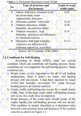
Based on ACI 224 R – 01, permitted maximum crack width is determined based on type of concrete structures and environment condition of concrete. For the structures which are influenced by corrosion, greatest crack widths are limited 0.15 mm. For indoor and impermeable structures, maximum crack widths are limited 0.41 mm. Permitted maximum crack width can be seen in Table 2.1.
Table 2. 1. Permitted Maximum Crack Width
No Type of structure and Enviroment Limit of crack width (mm) 1 Indoor strucrures, structure in dry
air enviroment, water impermeable structures
0.41
2 Structures contact with water 0.10
3 Outdoor structures, middle
humidity, no corrotion effect 0.30
4 Outdoor structures, high
humidity, structures are influenced by chemical reaction
0.18
5 Structures with high humidity, structures are influenced by corrotion (snow/ice, sea water)
0.15
Source: ACI Commite 224R (2001)
2.2.Conditions for Self-Healing
According to Heide (2005), there are several condition which can contribute self healing process. Some conditions are very important for self healing process. Some conditions are:
a. Water, water is very important to the all of self healing mechanisms. Thus if there’s no water, self healing process will not occure. It had been reported by Lauer (1956) that humidity enviroment 95٪ could decrease healing process in cracked concrete.
b. Cracks width, self-healing can occure for a small cracks width. Thus, in the large crack width, self healing prosess still occur, but crack close incompletely.
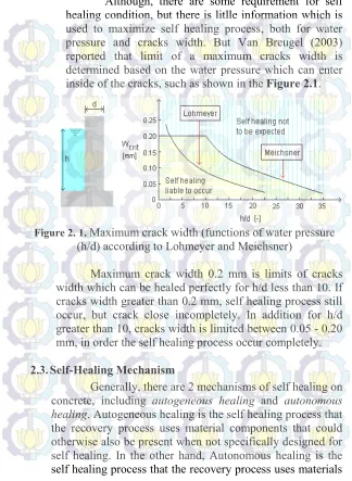
Although, there are some requirement for self healing condition, but there is litlle information which is used to maximize self healing process, both for water pressure and cracks width. But Van Breugel (2003) reported that limit of a maximum cracks width is determined based on the water pressure which can enter inside of the cracks, such as shown in the Figure 2.1.
Figure 2. 1. Maximum crack width (functions of water pressure (h/d) according to Lohmeyer and Meichsner)
Maximum crack width 0.2 mm is limits of cracks width which can be healed perfectly for h/d less than 10. If cracks width greater than 0.2 mm, self healing process still occur, but crack close incompletely. In addition for h/d greater than 10, cracks width is limited between 0.05 - 0.20 mm, in order the self healing process occur completely.
2.3.Self-Healing Mechanism
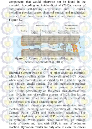
components that would otherwise not be found in the material. According to Reinhardt et al (2013), causes of autogeneous self-healing are divided into 3 causes, including physical cause, chemical causes, and mechanical causes. That three main mechanisms are shown in the Figure 2.2.
Figure 2. 2. Causes of autogeneous self-healing Source: Reinhardt et al (2013)
Physycal cause is due to the swelling process of Hidrated Cement Paste (HCP) or other additives materials which have swelling ability. The swelling of HCP occur, when water molecules are adsorbed by HCP and fill up the gap between cracks surface. But this mechanism produce low healing effectiveness. This is proven by reinhard (2013), that permeability on the crack area decrease less than 10%, in term of swelling process of HCP. But for the specific material which have swelling ability, permeability on the crack area could decrease up to 90٪.
up to 2 times from diameter of clinker cement. Thus, continued hydration of UCP close cracks incompletetly. But if cracks width less than or equal to 0.1 mm and by the assumption that HCP can swell and hydrate simultaneously, cracks can close completely. But if cracks width greater than 0.10 mm, the effects of this mechanism is very small.
Beside continued hydration, self healing process based on chemical causes are also contributed by carbonation reaction. This carbonation reaction occur, when Ca2+ ion react with carbonat (CO32-) ion to precipitate
Calcium Carbonate (CaCO3) crystal. This Calcium
Carbonate (CaCO3) is white crystal which can fill up the
cracks. This Ca2+ ions are suplied from Ca(OH)2 which is
resulted from cement hydration. And this carbonat (CO32-)
ions are came from water entering inside of crack. This carbonation reaction is influenced by temperature, ph, and reactants concentration. This carbonation reaction has high healing effectiveness, when compared to the other mechanisms (Edvarsen, 1996).
While mechanical causes are divided into 2 mechanisms, including particles which are carried by water and fracture of concrete particle which can blockage the cracks. But this two mechanisms give low effect to the self healing process of the cracked concrete.
Edvardsen (1996) used some assumptions to calculate hydration of clinker cement, as follows:
a. All these particles cements have same diameter size 50 µm (ro = 25µm)
b. After the hydration process occur completly, the volume of hydration particles cement which has been hydrated is 2 times from initial volume of undydrated cement particles before hydration process. V
1(α=100%) = 2 V0(α=0%)
c. Crack occur between aggregates and cement particles, so one side of crack is aggregate particle surface, and other one is cement particles surface.
Figure 2. 3. Model for calculating the self-healing mechanism based on continued hydration
(Source: Edvardsen, 1996)
The calculations had been done by Edvardsen (1996) and describe as follows:
V0 = 4/3 ⋅ π ⋅ r03
V1 = 4/3 ⋅ π ⋅ r13 = 2V0 r1 = 21/3 ⋅ r0 = 31.5 μm Δw = (r
1 - r0) ⋅ (1 - α) = (31.5 – 25) ⋅ 0.95 = 6 μm
Thus, only cracks width 6 μm or less than 6 μm can be healed perfectly by continued hydration mechanism. This
...( 1 )
calculation had been validated by Edvardsen (1996) through an experimental program. The result show, that cracks width 0.1 mm heal incompletely by continued hydration. Beside that, continued hydration mechanisms is only used to repair small cracks in early age (Naville, 2002)
In the concrete material, not all cement particles are hydrated at the beginning time after casting. Thus, the unhydrated clinkers are still available in concrete matrix. In most concrete with low w/c, the amount of unhydrated cement particles can reach up to 25٪ (Breugel, 2007). This unhydrated cement particles are still available in concrete matrix and can survive until long time. So, when cracks occur, the self-healing whic is contributed by continued hydration can occur (Li, 2007).
2.5. The influence of Pozzoland to Ca(OH)2 content
It has been explained on the sub chapter 2.3 that healing effectiveness is influenced one of them by the carbonation reaction. The carbonation reaction is very influenced by the amount of Ca(OH)2 in the concrete matrix.
Additional pozzoland material is able to reduce the amount of Ca(OH)2 in the early age of concrete (Reinhard, 2013).
Reducing Ca(OH)2 content is able to decrease self healing
process. This fact not only occur on cement Portland, but also on the blast furnace slag cement. Additional fly as, both in cement portland and blast furnace slag cement are able to reduce the amount of Ca(OH)2 at the age 365 days. The
amount of Ca(OH)2 for cement portland and blast furnace
slag cement are 8 gram/100 grams and 3 grams/100 grams respectively. So pozzoland which has low reactivity is more recommended to produce self healing behavior in concrete. The influence pozzoland fly ash to the Ca (OH)2
Figure 2. 4. Ca (OH)2 content based on cement type and additional pozzoland material
(Source: Reinhard et al, 2013) 2.6.Characteristics of Bentonite Clay
Bentonite is clay mineral which contain monmorilonite minerals and belong to dioktahedral group and also smectite group. Bentonite contains around 80٪ monmorilonite and others minerals such as kaolonite, illite, feldspar, gypsum, quartz, calcium carbonate in small portion. Bentonite is formed by chemical and mechanical process of rock which is influenced by weather (on the alkaline environment). That rocks are generally came from volcanic eruption, and also came from andesite, riolit, basal and others. Almost of them belong to tertiary rocks. Bentonite is spread in several area in Indonesia such as some area in Java, Sumatra, East Kalimantan and Sulawesi (Puslitbang Tekmira, 2005).
group of smectit with general chemical formula (Mg,Ca)O.Al2O3.5SiO2.nH2O. Bentonite is different from
others clay minerals, because it has almost 75% Montmirilonite minerals. Based on swelling ability of montmorilonite mineral, bentonites are divided into two categories, including: bentonite has polishing color. Suspension of Na-bentonite colloid in water has pH value 8.5 - 9.8.
b. Ca - bentonite
Ca–bentonite has low sweeling capacity when it is compared with Na–Bentonite. But Ca–bentonite has high adsorbtion capacity after it has been activated. In dry condtion, Ca–bentonite has gray, blue, yellow, and red colour. Suspension of Ca bentonite colloid has pH value 4.0 - 7.0.
Composition of Bentonite
As described above, bentonite has swelling capacity. It is mainly caused by montmorilonite minerals. When montmorilonite mineral contact with the water, there will be an ion exchange process between bentonite ion and water ion. This ion excanghe process contribute to the swelling properties of bentonite.
Table 2. 2. Composition of Bentonite (٪)
Source: Suryantoro, et al (1998)
2.7.Chemical Structure of Montmorolinite
According to Bergaya (2006), Montmorillonite (Mt) that is found in bentonite consists of 2 two tetrahedral layer and one octahedral layer. Tetrahedral layer consist of Si4+
cation which bound with 4 oxygen atom. While octahedral layer consists of Al3+ cation which bound with 6 hydroxyl ion
(OH-). When Montmorilonite (Mt) minerals contact with
Figure 2. 5. Chemical structure of Montmorollonite (Source: Li 1995)
Table 2. 3. Chemical Compounds of Bentonite
Oksida Na – Bentonite (%) Ca – Bentonite (%)
SiO2 61.3 – 61.4 % 62,12 %
Al2O3 19.8 % 17.33 %
Fe2O3 3.9 % 5.30 %
CaO 0.6 % 3.68 %
MgO 1.3 % 3.30 %
Na2O 2.2 % 0.50 %
K2O 0.4 % 0.55 %
H2O 7.2 % 7.22 %
2.8. Autogenous Healing Concrete using Geomaterial
Ahn and Kishi (2009) reported about influence of geomaterial incorporating expansive agent to the self healing behaviour of cracked concrete by using contant water per binder w/b = 0.45. The geomaterial contains SiO2 and Al2O3
about 71.30% dan 15.4 % respectively. From the XRD analysis, it is known that geomaterial A contain sodium Silicate Aluminum Hidroxyde [Na0.6Al4.70Si7.32O20(OH)4]
mineral which is identified as montmorillonite mineral. Beside montmorillonite mineral, Geomateria A is also identified as feldspar, and quartz in small portion. Geomaterial is used in this research, because it has montmorillonite minerals which have swelling capacity. From the research result, it is found that combination of cement paste [OPC90% + CSA5% + Geo-material 5%] give the best healing capacity. Initial crack 0.2 mm could be healed perfectly after 28 age days by using this composition as shown in Figure 2.6. Healing product closing cracks are observed after 14 age days, and cracks are almost closed perfectly after 200 age days curing time.
X-Ray mapping is carry out by Ahn and Kishi (2009) to analize mechanism of self healing occurred in the spcimens. From testing result, mineral closing crack is almost identified as Alumina Silicate as shown in Figure 2.7. Self healing zone and original zone are observed to understand mechanism in the two zone. Self healing zone is identified as gehelite phase (CASH) with high alumina ion when compared with original zone. So it can be concluded that calcium Hidroksida (Ca(OH)2) which is resulted from
Figure 2. 6. Self-healing [OPC90٪+CSA5٪+Geo 5٪] Source: Ahn and Kishi (2009)
Figure 2. 7. A comparison X-Ray mapping between self healing zone and original zone
Source: Ahn and Kishi (2009)
According to Ahn and Kishi (2009), alkaline activator of geomaterial A in presence of Ca(OH)2 which is resulted
geopolimer gell in high alkaline environment. Figure 2.8 shows the difference between geopolimer gel in the self healing zone and hydrogarnet in the original zone by using scaning electron microscope (SEM). Geopolimer gell size in self healing zone is less than 2µm. In addition, the modified geopolimer gell in self healing zone is structured by dense phases as compared to Hydrogarnet phases in original zone.
Figure 2. 8. A comparison geopolimer gell in the self-healing zone with Hydrogarnet in original zone
(Source: Ahn and Kishi, 2009)
From the research which have been conducted by Ahn and Kishi (2009) above, it is known that Geomaterial A have ability as healing agent, but Ahn and Kishi didn’t explain specifically about this Geomaterial.
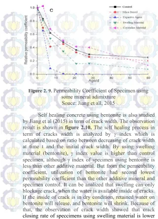
Figure 2. 9. Permeability Coefficient of Specimen using some mineral adimixture
Souce: Jiang et all, 2015
than the other additive mineral. Releasing of retained water from bentonite is very beneficial to generate self healing mechanism in term of continued hidration and carbonation process, especially for cracked concrete in dry environment.
Figure 2. 10. Index value of Specimen using some mineral adimixture
Souce: Jiang et all, 2015
Figure 2. 11. Flexural strength of cracked concrete using nanoclay for different curing conditions and precracking time
Source: Jiang et all, 2015
2.9.Blast Furnace Slag as Autogenous Healing material Blast furnace slag can be used as autogeneous healing material in concrete because of its latent hydraulic properties. Autogenenous healing behavior of cement paste incorporating BFS had been studied by Tittelboom et al (2012) in term of crack width and cumulative head produce by hydration process.
According to Tittelboom et al (2012), for crack width in the range of 0 – 125 m (Figure 2.12), replacement some clinker cement with BFS resulted lower healing effectiveness (shown by value) compared to OPC (CEM I). This fact is contributed by amount of Ca (OH)2 in
Figure 2. 12. Crack self-closing ratio (Source: Tittelboom et al, 2012)
Beside of crack closing rate, the cumulative heat production which is measured by the TAM AIR calorimeter is also analyzed by Tittelboom et al (2012). The result is shown in Fig. 2.13. It is noticed that in the beginning (first 45 h of rewetting), most heat is produced by the crushed CEM I (Ordinary Portland cement) specimen. As cement is a hydraulic binder, unreacted cement grains, present in the crushed cement paste, react fast upon contact with water and hereby release hydration heat.
Increasing the percentage of blast furnace slag does not seem to increase the cumulative heat production within the first 140 h after mixing. This is noted as the curve which is obtained for the 85 BFS mix is plotted below the 50 BFS mix curve. Although the heat production rate is almost same (as both curves show a parallel course), initially more heat is produced by the 50 BFS mix. This may be caused by the fact that less Ca(OH)2 becomes available from the hydrated
clinker to activate the blast furnace slag reaction, when higher replacement percentages are used. Although, the cumulative heat production after 1 week is lower for higher percentages of blast furnace slag, it should be noticed that due to the fact that more unhydrated slag particles will be available in mixes with high amounts of blast furnace slag, hydration may continue for a longer period.
As the composition of a CEM III cement is similar to the composition of the mixture where 85% of the cement weight is replaced by blast furnace slag, it can be expected that both heat production curves follow the same course which is also observed
Figure 2. 13. Cumulative heat production Q [J/g] for the different mixtures under investigation
Autogeneus healing behavior of cement paste with blast furnace slag as partial cement replacement also has been studied by Huang et al (2014). The healing mechanism is mainly influenced by physical and chemical mechanisms. Cement with 66% BFS as partial cement replacement able to close cracks width which is occurred in concrete. Self healing process in term of closing crack width is due to some chemical reaction occurred inside of the cracks. Result of this chemicals reaction are C – S – H, ettringite, hydrogarnet and OH-hydrotalcite. But the highest percentage mineral closing crack is identified as C - S – H gell from the other minerals. The formation of C - S – H gell fraction is due to BFS particles which is activated by Ca2+
ion from the alkaline environment of the concrete. After BFS particles has been activated, BFS can react with water to produce C – S – H gell. The filling fraction mineral of the craks are shown in Figure 2.14. The highest mineral closing crack is C - S – H, and then followed by Etrringite minerals, Hydrotalcite minerals and C3AH6 in small amount.
Figure 2. 14. Influence of carbonation degrees to the fillliing fraction of crack
According to Huang et al (2014), fraction of minerals formed in cracks could change when carbonation reaction occurred inside cracks. Figure 2.15 showed the influence of carbonation degrees to self healing effectiveness by using BFS as patial cement replacement. In the initial phase, when carbonation degree 0 – 2%, amount of filling fraction of crack increase from 54% to 56%. But this value decrease from 56% to 47% when the faction mineral inside cracks has been hydrated perfectly.
Figure 2. 15. Faction minerals which close the crack Source: Huang et al, 2014
Self healing mechanims with Blast Furnace Slag (BFS) is also studied by Sukumar and Depaa (2013), where the self-healing parameter is analyzed based on compresif strenght, flexural strenght and splitting tensile strength after cracking. BFS replacement used is 0%, 35%, and 35%. From three parameter of self healing, optimum percentage BFS replacement is 35%.
Figure 2. 16. Influence of BFS replacement to Flexural strength concrete after cracking
(Source: Sukumar and Depaa, 2013)
Figure 2. 17. Influence of BFS replacement to Splitting tensile strength concrete after cracking
Figure 2. 18. Influence of BFS replacement to compresif strength concrete after cracking
(Source: Sukumar and Depaa, 2013)
According to Sukumar and Depaa (2013), self healing process is totally influenced by continued hydration of unhydrated BFS particles. So if crack occur, hydration process run. This hydration results had characteristics as
bonding agent as well as filling agent. Bonding agent function can be seen from the inceasing of compresif strength after cracking with 35٪ BFS replacement.
Figure 2. 19. Maximum crack width for 100% healing (Source: Palin et al, 2015)
Figure 2. 20. Crack healing percentage as a function of the initial crack width for A) fresh water and B) sea water
(Source: Palin et al, 2015)
Figure 2. 21. Chloride ion permeability of ECC mixtures using slag due to repetitive preloading
(Source: Sahmaran et al, 2015)
Figure 2. 22. Total crack closure rates of ECC mixtures with slag specimens due to self healing
35 RESEARCH METHODOLOGY
Figure 3. 1. Flowchart of Research Methodology
3.1.Literature Riview
3.2.Preparation of Materials
Preparation of raw materials, include : a. Ordinary Portland Cement (OPC)
Cement whic is used in this research is cement type 1/Ordinary Portland Cement (OPC) that is gotten from PT. Semen Indonesia, Tbk. OPC is used in this research because, there is no influence of healing process from others material such as pozzoland material in PPC or other composite material in PCC.
b. Bentonite
There are two types of bentonite, including Na – Bentonite and Ca – Bentonite. However, Ca bentonite is choosen in this reserach because it has low shrinkage properties. The bentonite is gotten from PT. Nusa Indah Megah.
c. Blast Furnace Slag
Blast furnace slag which is used in this reseach is gotten from PT. Krakatau Steel Industri, Tbk. Real condition of BFS is granulated particles (ground granulated blast furnace slag). Because of that, BFS must be grinded firstly for 12 hour by using Ball mill to get specific surface area of BFS particle arround 3000 cm2/gram.
d. Water
The water used in this research is tap water.
3.3. Analisys of Raw Materials Properties 3.3.1. Method to Determine Specific Gravity
a. Apparatus
1. Pycnometer 500 mL 2. Specimen chamber 3. Pipet and Funnel
4. Balance with precision 1 gram b. Testing Procedure
1. Measure weight of material sample as weight as 150 gram by using balance
2. Prepare pycnometer with volume capacity 500 mL Then measure weigth of picnometer (Wp)
3. Introduce sample into pycnometer. Then measure and record weight of picometer+sample (Wpm)
4. Calculate weight of tested sample (A = Wpm - Wp)
5. Fill pycnometer partially with kerosene, approximately 90% of the volume capacity of pycnometer.
6. Roll, invert, and agitate pycnometer to eliminate all air bubbles.
7. Fill again pycnometer with additional kerosene until volume capacity marking of pycnometer and then measure weigh of picometer + sample materials + kerosene and record the weight (B). 8. Material sample and kerosene are removed from
pycnometer and pycnometer is cleaned with kerosene for next steps
Where:
3.3.2. Method to Determine Density
This method is conducted according to ASTM C29. This method is conducted to determine dry density of each materials which is used in this research, that’s OPC, bentonite, and BFS. Density of fine material is defined as the ratio of its particle weight to volume of measure. Weight of particles consist of 3 methods, include rodding, jigging, and shoveling procedure.
a. Apparatus
1. Balance with precision 5 gram
2. Tamping rod made from steel with diameter and length are 15 mm and 610 mm respectively. 3. Measure is cylindrical which is made from steel
and water impermeable. 4. Oven
b. Testing Procedure
1. Dry the sample of materials in an oven until get constant mass
Calibration of measure
2. Fill the measure with water and cover with a piece of plate glass.
3. Determine the mass of the water.
4. Measure the temperature of the water to find its density
5. Calculate the factor for the measure
Rodding procedure
6. Fill the measure one – third full and leveling the surface with finger.
7. Rod the layer 25 stroke with tamping rod without striking the bottom of the measure.
8. Fill the measure two–third full and leveling the surface as before with the finger
9. Rodd the layer again as before, just penetrating previous layer.
10. Fill the measure to overflowing
11. Rodd the layer again as before, just penetrating previous layer.
12. Level the surface with finger or tamping rod. 13. Determine the mass of the measure and sample
content (A), and the measure alone (B), and then record to nearest 0.05 Kg.
14. Calculate value of unit weight using equation in poin c and the calibration factor
Jigging Procedure
5. Fill the measure one – third full and leveling the surface with finger.
6. Raise the measure 50 mm and drop the measure on firm base 50 time (25 time on each side). 7. Fill the measure two – third full and level again
the surface as before.
8. Raise and drop again 50 time as before. 9. Fill the measure to overflowing. 10. Raise and drop again 50 time as before. 11. Level the surface with finger or tamping rod. 12. Determine the mass of the measure and sample
content (A), and the measure alone (B), and then record to nearest 5 gram.
Shoveling Procedure
6 Fill the measure to overflowing by means of shovel or scoop discharging the materials samples from a height not exceed 50 mm above the top of measure.
7 Level the surface with finger or tamping rod. 8 Determine the mass of the measure and sample
content (A), and the measure alone (B), and then record to nearest 5 gram
9 Calculate value of unit weight using equation in poin c and the calibration factor
c. Calculation
Value of density for each fine materials are calculated based on average of density gotten from 3 procedure include rodding, jigging and shoveling procedure. Density for each procedure is calculated base on following formula:
3.3.3. Method to determine SAI
This method is conducted according to ASTM 593 - 95. This method is conducted to determine strength activity index (SAI) of each material. Strenght acitivity index of material is defined as ratio between compressive strength of mortar mixtures and mortar using OPC as reference mixture. All mortar mixtures must be cured by using steam curing on 38±2oC for 7 days.
a. Apparatus
1. Balance with precision 0.1 gram 2. Measure glass
3. Mixer 4. Tamping rod
5. Mortar cylinder mold with dimater and height are 5 cm and 10 cm respectively.
b. Testing Procedure
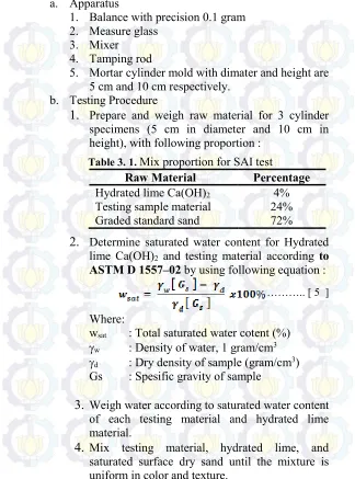
1.
Prepare and weigh raw material for 3 cylinder specimens (5 cm in diameter and 10 cm in height), with following proportion :Table 3. 1. Mix proportion for SAI test
Raw Material Percentage
Hydrated lime Ca(OH)2 4%
Testing sample material 24%
Graded standard sand 72%
2.
Determine saturated water content for Hydrated lime Ca(OH)2 and testing material according toASTM D 1557–02 by using following equation :
Where:
wsat : Total saturated water cotent (%)
w : Density of water, 1 gram/cm3
d : Dry density of sample (gram/cm3)
Gs : Spesific gravity of sample
3.
Weigh water according to saturated water content
of each testing material and hydrated lime material.
4.
Mix testing material, hydrated lime, and
saturated surface dry sand until the mixture is uniform in color and texture.
5.
Add water to the mixtures gradually until the mixtures are homogeny, saturated condition and uniform colour.6.
After saturated mixtures are gotten, cast the specimens immediately in accordance with Method C of Test Methods D 1557. Each layer should be scarified to a depth of 6 mm before the next layer is compacted in order to assure a good bond between the layers.7.
After specimen mold is full, surface of cylinder specimen should be levelled using tamping rod.8.
Remove specimen from the molding carefully, because the mixture belong to dry mixture.9.
After removing specimens, mortar specimens are put on flat surface.10.
Mortar specimens are cured by using steam
curing machine on 38 ± 2o C for 7 days.
11.
After 7 days steam curing periods, mortar
specimen are removed and weighed.
12.
Then mortar specimens are submerged into the
water for 4 hour, and then dried for 1 hours.13.
Mortar specimens are capped and subjected to
the compresif strength test based on ASTM C 39.c. Calculation
Value of specific gravity for each fine material is calculated based on following equation:
Where:
SAI : Strengt activity index
P : Applied load
A : Surface area of specimens
3.3.4. Flow Table Test
This test is conducted to determine water/binder for each series to get same value of consistency (flowability). This test is conducted according to ASTM C 1437 – 07.
6 in.) in length, with straight edges.
5. Straightedge, made of steel, shall be at least 200
mm in lenght and not less than 1.5 mm nor more than 3.5 mm in thickness.
b. Testing Procedure
1. Clean and dry flow table carefully, and then place the flow mold at the center of flow table. 2. Place a layer of mortar about 25 mm (1 in.) in
thickness in the mold and tamp 20 times with the tamper. The tamping pressure shall be just sufficient to ensure uniform filling of the mold. 3. Then fill the mold with mortar and tamp as
specified for the first layer.
4. Cut off the mortar to a plane surface flush with the top of the mold by drawing the straightedge or the edge of the trowel with a sawing motion across the top of the mold.
5. Wipe, clean and dry the table top, and remove carefully any water from around the edge of the flow mold.
6. Lift the mold away from the mortar 1 min after completing the casting operation.
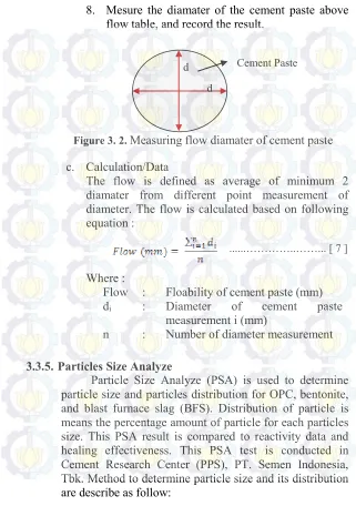
8. Mesure the diamater of the cement paste above flow table, and record the result.
Figure 3. 2. Measuring flow diamater of cement paste c. Calculation/Data
The flow is defined as average of minimum 2 diamater from different point measurement of diameter. The flow is calculated based on following equation :
Where :
Flow : Floability of cement paste (mm)
di : Diameter of cement paste
measurement i (mm)
n : Number of diameter measurement
3.3.5. Particles Size Analyze
a. Apparatus
1. Malvern instrument for PSD analysis 2. Spatula
3. Specimen chamber b. Testing Procedure
1. Introduce material sample to specimen chamber by using spatula.
2. Put specimen chamber containg material sample to the Malvern instrument.
3. Choose material reference in Malvern software for each material.
4. Run sample until process finish.
5. Remove sample from the Malvern instrument and from chambers.
c. Calculation/Data
Data from this testing are distribution of each particle size that is shown by distribution particle curve. This curve consist of particles size in x axis and percentage particles in Y axis.
3.3.6. X-Ray Fluoroscene
X – Ray Fluoroscene is used to determine chemical element and its percentage of raw materials such as OPC, bentonite, and Blast furnace slag. This chemical element
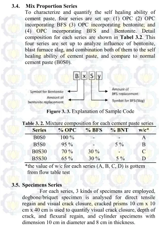
3.4. Mix Proportion Series
To characterize and quantify the self healing ability of cement paste, four series are set up: (1) OPC (2) OPC incorporating BFS (3) OPC incorporating bentonite; and (4) OPC incorporating BFS and Bentonite. Detail composition for each series are shown in Tabel 3.2. This four series are set up to analyze influence of bentonite, blast furnace slag, and combination both of them to the self healing ability of cement paste, and compare to normal cement paste (B0S0).
Figure 3. 3. Explanation of Sample Code
Table 3. 2. Mixture composition for each cement paste series
Series % OPC % BFS % BNT w/c*
B0S0 100 % - - A
B5S0 95 % - 5 % B
B0S30 70 % 30 % - C
B5S30 65 % 30 % 5 % D
*the value of w/c for each series (A, B, C, D) is gottem from flow table test
3.5. Specimens Series
3.5.1. Dogbone/Briquet Specimen
Dogbone/briquet specimens are carried out to determine direct tensile regain after crack. Detail specification of dogbone specimens are shown in Figure 3.4 bellow.
Figure 3. 4. Detail specification of briquet Source: CRD-C 260-01
3.5.2. Beam 10 x 10 x 40
Figure 3. 5. Dimension of Beam specimens
Figure 3. 6. Crack initiation by indtroducing teflon sheet as depth as 5 mm
Figure 3. 7. Detail of steel reinforcement
40 cm
10 cm
10 cm
Crack initiation by introducing teflon sheet as depth as 5 mmBeam Specimens
15 cm
10 cm
15 cm Crack initiation by introducing
3.5.3. Cylinder Specimens
Cylinder specimens with diameter 10 cm and thickness 8 cm were carried out to determine cloride penetration. Detail specification of specimens are shown in Figure 3.8. Before permeability testing, cyliner specimen were subjected to splitting test to introduce artificial crack. During splitting test, cylinder specimens were confined by using duct tape to control crack width. Then cracked cylinder specimens were coated by using waterprof on cover side of cylinder specimens. Coated specimens were shown in Fig.3.9.(a). Then, specimens were put in pipe and put waterprof on top and bottom of cylinder specimen only put on circumference line of cylinder specimen ( see Fig. 3.9.(b) ).
Figure 3. 8. Cylinder specimens
Figure 3. 9. Coated specimens, a) cover side b) top side
8 cm
10 cm
a
b
3.6. Specimens Casting
Specimen used in this research is cement paste incoporating some material such as bentonite and BFS as partial cement replacement. Procedure for specimen casting is described as follow:
a. Apparatus 1. Mixer machine
2. Molds for 3 specimens (Briquet, beam, and cylinder) 3. Steel reinforcement
4. Leveling apparatus (ex : Rule) 5. Rubber hammer
6. Balance with precision 1 gram b. Procedures
1. Prepare molding for 3 kinds of specimen (Briquet, Beam 10 x 10 x 40, and cylinder 10 cm in diameter and 8 cm in thickness) and reinforcement for beam 10 x 10 x 40.
2. Introduce oil inside of molding suface in order the specimen can be removed easily from the mold. 3. Measure weight all of materials (OPC, bentonite,
BFS, and water) based on mixture proportion for each series in sub chapter 3.4.
4. Introduce OPC, bentonite, and BFS into mixer chamber, and mix material with low speed for 2 minutes until the mixture has same colour.
5. Stop mixer machine and then introduce some water (don’t introduce the all of water) to the mixtures, and then mix again with low speed for 2 minutes until the mixtures homogen.
6. Stop mixer machine and introduce additional water to the mixtures, and then mix again with middle speed for 4 minutes until the mixtures homogen. 7. Remove mixtures from the mixer machine, and then
8. Fill again the mixtures into the mold two – third full, and compact specimen with rubber hammer.
9. Fill again the cement mixtures into the mold until overflowing, and then compact specimen with rubber hammer.
10. Level the specimen surface with ruller.
11. Introduce mica (ticknes 0.1 mm) to the beam specimens as depth as 5 mm to initiate artificial crack occure in that point.
12. Remove specimens from the mold after 24 hour after casting process.
13. And then cure specimen into wet curing condition
3.7. Curing Condition
All of the specimens were cured in wet curing condition until introducing artificial crack. Wet curing was conditioned by wraping all specimen by using wet burlap. Then the wet burlap was maintenanced always on the wet condition. 1 day before introducing artificial crack on 28 age days after casting, specimens were removed from wet curing condition, and then dried by using air condition.
3.8. Introducing Artificial Crack
Artificial cracks were created by using 3 methods based on type of specimens. Dogbone/briquet specimens were subjected to direct tensile test until specimen separate become two part, and then two part were connected become 1 part specimen and then 1 part specimen was holded by using dogbone specimen holder. Prisms 10 cm x 10 cm x 40 cm specimens were subjected to four point bending test until crack occur. Cylinder specimens were subjected to splitting test until the crack occur. Cracked width of all specimens are controlled under 0.3 mm that is maximum cracks width permitted by ACI 224R-01.
a b
Figure 3. 11. Introducing artificial crack, a) Cylinder specimens by using splitting test, b) beam specimens by
using four point bending test
a b
Figure 3. 12. a ) Introducing artificial crack of dogbone specimens by using tensile test, b) dogbone specimens are
3.9. Water Imersion Curing
After all of specimens have been cracked, then the all of specimens are cured again by immersing specimens in water. 1 day before observation and measurement on 7, 14, 28, and 56 age days after introducing artificial crack, specimen are removed from wet curing process, and then dry using air condition.
Figure 3. 13. Water Imersion Curing
3.10. Self Healing Evaluation
Five kinds of testing and measurement are carried out to evaluate self healing behavior of the cement paste specimens, including ultrasonic pulse velocity testing, microscopic investigation, direst tensile testing, and flexural testing. That testing and measurement are explained as below:
3.10.1. Ultrasonic Pulse Velocity Testing
Ultrasnic pulse velocity is carried out to evaluate self healing process of specimens, in term of crack depth changes on 0, 7, 14, 28, and 56 days after cracking. This method is conducted according to
a.Apparatus
The testing apparatus is shown schematically in Figure 3.14, consists of a pulse generator, a pair of transducers (transmitting transducer and receiving transducer), a receiver amplifier, a time measuring circuit, a time display unit, and connecting cables. Beside that, cracked beam is prepared for this testing and measurement.
Figure 3. 14. Schematic of Pulse Velocity Apparatus Source: ASTM C597 – 02
b. Testing Procedure
1. Verify that the UPV equipment is operating properlyand perform a zero-time adjustment. Perfome a zero time adjustment using
Automatic Zero-Time Adjustment by Apply
coupling agent to the transducer faces and press the faces together.