Open Geospatial Consortium
Date: 2011-11-23
Reference number of this document: OGC 11-089r1
Category: Public Engineering Report
Editor:Daniel Tagesson
OGC
®OWS-8 Engineering Report - Guidelines for
International Civil Aviation Organization (ICAO) portrayal
using SLD/SE
Copyright © 2011 Open Geospatial Consortium.
To obtain additional rights of use, visit http://www.opengeospatial.org/legal/.
Warning
This document is not an OGC Standard. This document is an OGC Public
Engineering Report created as a deliverable in an OGC Interoperability Initiative and is not an official position of the OGC membership. It is distributed for review and comment. It is subject to change without notice and may not be referred to as an OGC Standard. Further, any OGC Engineering Report should not be referenced as required or mandatory technology in procurements.
.
Document type: OpenGIS® Public Engineering Report Document subtype: NA
Preface
This document is a deliverable for the OGC Web Services 8 (OWS-8) testbed activity. OWS testbeds are part of OGC's Interoperability Program, a global, hands-on and collaborative prototyping program designed to rapidly develop, test and deliver proven candidate standards or revisions to existing standards into OGC's Standards Program, where they are formalized for public release. In OGC's Interoperability Initiatives,
international teams of technology providers work together to solve specific geoprocessing interoperability problems posed by the Initiative's sponsoring organizations. OGC
Interoperability Initiatives include test beds, pilot projects, interoperability experiments and interoperability support services - all designed to encourage rapid development, testing, validation and adoption of OGC standards.
The OWS-8 sponsors are organizations seeking open standards for their interoperability requirements. After analyzing their requirements, the OGC Interoperability Team recommended to the sponsors that the content of the OWS-8 initiative be organized around the following threads:
* Observation Fusion
* Geosynchronization (Gsync)
* Cross-Community Interoperability (CCI) * Aviation
More information about the OWS-8 testbed can be found at:
http://www.opengeospatial.org/standards/requests/74
OGC Document [11-139] “OWS-8 Summary Report” provides a summary of the OWS-8 testbed and is available for download:
License Agreement
Open Geospatial Consortium, OGC, OPENGIS, and the OGC CERTIFIED COMPLIANT logo are registered trademarks or trademarks of Licensor in the United States and in other countries.
Permission is hereby granted by the Open Geospatial Consortium (“Licensor”), free of charge and subject to the terms set forth below, to any person obtaining a copy of this Intellectual Property and any associated documentation, to deal in the Intellectual Property without restriction (except as set forth below), including without limitation the rights to implement, use, copy, modify, merge, publish, distribute, and/or sublicense copies of the Intellectual Property, and to permit persons to whom the Intellectual Property is furnished to do so, provided that all copyright notices on the intellectual property are retained intact and that each person to whom the Intellectual Property is furnished agrees to the terms of this Agreement.
If you modify the Intellectual Property, all copies of the modified Intellectual Property must include, in addition to the above copyright notice, a notice that the Intellectual Property includes modifications that have not been approved or adopted by LICENSOR.
THIS LICENSE IS A COPYRIGHT LICENSE ONLY, AND DOES NOT CONVEY ANY RIGHTS UNDER ANY PATENTS THAT MAY BE IN FORCE ANYWHERE IN THE WORLD.
THE INTELLECTUAL PROPERTY IS PROVIDED "AS IS", WITHOUT WARRANTY OF ANY KIND, EXPRESS OR IMPLIED, INCLUDING BUT NOT LIMITED TO THE WARRANTIES OF MERCHANTABILITY, FITNESS FOR A PARTICULAR PURPOSE, AND NONINFRINGEMENT OF THIRD PARTY RIGHTS. THE COPYRIGHT HOLDER OR HOLDERS INCLUDED IN THIS NOTICE DO NOT WARRANT THAT THE FUNCTIONS CONTAINED IN THE INTELLECTUAL PROPERTY WILL MEET YOUR REQUIREMENTS OR THAT THE OPERATION OF THE INTELLECTUAL PROPERTY WILL BE UNINTERRUPTED OR ERROR FREE. ANY USE OF THE INTELLECTUAL PROPERTY SHALL BE MADE ENTIRELY AT THE USER’S OWN RISK. IN NO EVENT SHALL THE COPYRIGHT HOLDER OR ANY CONTRIBUTOR OF INTELLECTUAL PROPERTY RIGHTS TO THE INTELLECTUAL PROPERTY BE LIABLE FOR ANY CLAIM, OR ANY DIRECT, SPECIAL, INDIRECT OR CONSEQUENTIAL DAMAGES, OR ANY DAMAGES WHATSOEVER RESULTING FROM ANY ALLEGED INFRINGEMENT OR ANY LOSS OF USE, DATA OR PROFITS, WHETHER IN AN ACTION OF CONTRACT, NEGLIGENCE OR UNDER ANY OTHER LEGAL THEORY, ARISING OUT OF OR IN CONNECTION WITH THE IMPLEMENTATION, USE, COMMERCIALIZATION OR PERFORMANCE OF THIS INTELLECTUAL PROPERTY.
This license is effective until terminated. You may terminate it at any time by destroying the Intellectual Property together with all copies in any form. The license will also terminate if you fail to comply with any term or condition of this Agreement. Except as provided in the following sentence, no such termination of this license shall require the termination of any third party end-user sublicense to the Intellectual Property which is in force as of the date of notice of such termination. In addition, should the Intellectual Property, or the operation of the Intellectual Property, infringe, or in LICENSOR’s sole opinion be likely to infringe, any patent, copyright, trademark or other right of a third party, you agree that LICENSOR, in its sole discretion, may terminate this license without any compensation or liability to you, your licensees or any other party. You agree upon termination of any kind to destroy or cause to be destroyed the Intellectual Property together with all copies in any form, whether held by you or by any third party.
Except as contained in this notice, the name of LICENSOR or of any other holder of a copyright in all or part of the Intellectual Property shall not be used in advertising or otherwise to promote the sale, use or other dealings in this Intellectual Property without prior written authorization of LICENSOR or such copyright holder. LICENSOR is and shall at all times be the sole entity that may authorize you or any third party to use certification marks, trademarks or other special designations to indicate compliance with any LICENSOR standards or specifications.
This Agreement is governed by the laws of the Commonwealth of Massachusetts. The application to this Agreement of the United Nations Convention on Contracts for the International Sale of Goods is hereby expressly excluded. In the event any provision of this Agreement shall be deemed unenforceable, void or invalid, such provision shall be modified so as to make it valid and enforceable, and as so modified the entire Agreement shall remain in full force and effect. No decision, action or inaction by LICENSOR shall be construed to be a waiver of any rights or remedies available to it.
Contents
Page1 Introduction ... 1
1.1 Scope ... 1
1.2 Document contributor contact points ... 1
1.3 Revision history ... 1
1.4 Future work ... 2
1.5 Foreword ... 2
2 References ... 2
3 Terms and definitions ... 3
4 Conventions ... 3
4.1 Abbreviated terms ... 3
4.2 UML notation ... 3
5 Guidelines for ICAO portrayal using SLD/SE overview ... 3
5.1 Focus ... 3
6 Issues ... 4
6.1 Cartographic/Presentation limitations ... 4
6.1.1 ICAO Airspace band style ... 4
6.1.2 Special patterns ... 4
6.1.3 Label deconfliction ... 4
6.2 Data dependent ... 4
6.3 Portrayal of status information ... 4
7 Guidelines and solutions to issues ... 5
7.1 Cartographic/Presentation limitations ... 5
7.1.1 ICAO Airspace band style ... 5
7.1.2 Special patterns ... 7
7.1.3 ICAO Restricted airspace styling ... 12
7.1.4 Airways ... 13
7.1.5 Label deconfliction ... 14
7.2 Data dependent ... 15
7.2.1 Specifying geometries in symbolizers ... 16
7.2.2 Portrayal of hierarchical data ... 16
7.2.3 Portrayal of relational data ... 17
7.2.4 AIXM Temporality ... 22
7.3 Portrayal of status information ... 22
7.3.1 Closed/unserviceable features ... 22
7.3.2 Contamination ... 27
7.4 Enterprise Considerations ... 29
7.4.1 Algorithmic Rules ... 29
7.4.2 Delineations ... 31
1 Introduction ... 33
1.1 Purpose and Scope ... 33
1.2 Abbreviations ... 33
1.3 References and Supporting documents ... 34
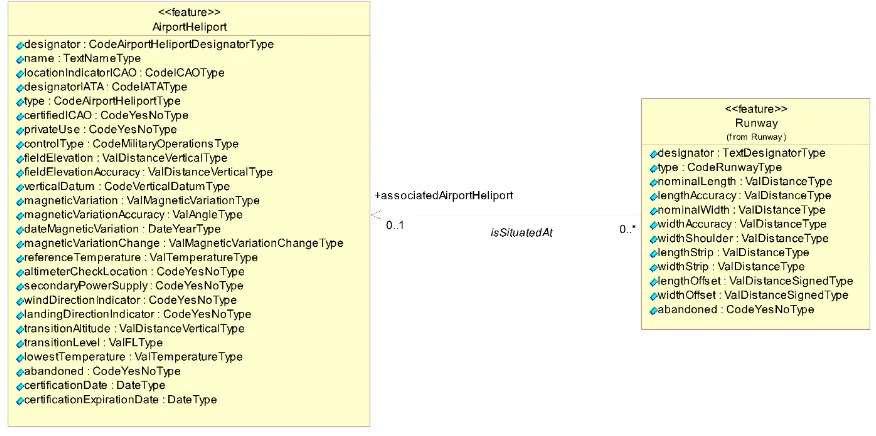
2 Directional Associations in the AIXM Application Schema and Ramifications to Portrayal ... 35
3 AIXM Portrayal using OGC Symbology Encoding ... 39
3.1 Revise the AIXM Application Schema ... 40
3.2 Extend the OGC Symbology Encoding ... 40
Annex B - Styling of AIXM 5.1 light systems using composite rules ... 43
1 Introduction ... 43
1.1 Composite rule schema ... 44
1.2 SE example ... 44
1.3 Data sample ... 47
Annex C - Change Request - SE Symbolizer and Rule for styling of nested child objects ... 53
1 Source ... 53
2 Category ... 53
3 Reason for change ... 53
4 Summary of change ... 53
5 Consequences if not approved ... 55
Figures
PageFigure 1 - ICAO Airspace style 5
Figure 2 - ICAO fill style examples 9
Figure 3 - ICAO ATS line styles 10
Figure 4 - ICAO Restricted airspace styling 12
Figure 5 - Line with repeated symbol 12
Figure 6 - Restricted airspaces alternate visualization 13
Figure 7 - Airway symbol example 13
Figure 8 - Surface status visualization example 23
Figure 9 — Close-up of hatched filled Runway with (Right) and without (Left) additional
outline 25
Figure 10 — Zoomed out view of hatched filled Runway with (Right) and without (Left)
additional outline 25
Figure 12 — SNOWTAM symbols. 27
Figure 13 - SE Fragment Symbolizing Aerodrome based on its Aircraft Type 36
Figure 14 - AIXM 5.1 UML – AirportHeliport / Runway Association 37
Figure 15 - AIXM 5.1 XSD – AirportHeliport Properties 39
Figure 16 - AIXM 5.1 XSD – Runway Properties 39
Figure 17 - Revised AIXM UML – AirportHeliport / Runway Association 40
Figure 18 - Referring to Runway nominalLength via AssociatedProperty 41
Figure 19 - XSD Representation of AssociatedProperty 42
Tables
PageOGC
®OWS-8 Engineering Report - Guidelines for ICAO
portrayal using SLD/SE
1 Introduction
1.1 Scope
This OGC® document gives guidelines to portrayal of AIXM according to ICAO aviation
symbology using SLD/SE.
1.2 Document contributor contact points
All questions regarding this document should be directed to the editor or the contributors:
Name Organization
Örjan Kvartsberg Carmenta
Daniel Tagesson Carmenta
Jeroen Dries Luciad
Simon Merrick Envitia
Alex Brooker Envitia
1.3 Revision history
Date Release Editor Primary clauses modified
Description
2011-05-06 Draft 1 Örjan Kvartsberg Initial draft An initial draft of the document. Mainly layout
2011-05-09 Draft 2 Daniel Tagesson Various Added general sections on the scope and focus of the document.
2011-05-16 Draft 3 Daniel Tagesson Various
2011-06-20 Draft 4 Daniel Tagesson 6 and 7 Updated per feedback from Eurocontrol and added new information from Envitia.
2011-07-27 Draft 5 Daniel Tagesson Title and headers Set OGC document number 11-089.
2011-08-27 Draft 6 Daniel Tagesson Various Updated to final draft
2011-09-29 Final Daniel Tagesson Various Minor updates for the release version
1.4 Future work
A number of areas have been identified for future work.
How to support composite graphics, such as that required to properly visualize runway segments. See chapter 7.1.4.
Solutions to the Directional Associations issues as discussed in Annex A.
Further work on composite child symbolizers and composite rules as discussed in Annex B.
Implementing portrayal for ICAO weather symbology according to ICAO Annex 3, using SLD/SE has not been explored and needs to be investigated.
1.5 Foreword
Attention is drawn to the possibility that some of the elements of this document may be the subject of patent rights. The Open Geospatial Consortium Inc. shall not be held responsible for identifying any or all such patent rights.
Recipients of this document are requested to submit, with their comments, notification of any relevant patent claims or other intellectual property rights of which they may be aware that might be infringed by any implementation of the standard set forth in this document, and to provide supporting documentation.
2 References
The following documents are referenced in this document. For dated references, subsequent amendments to, or revisions of, any of these publications do not apply. For undated references, the latest edition of the normative document referred to applies. OGC 06-121r3, OpenGIS® Web Services Common Standard
NOTE This OWS Common Specification contains a list of normative references that are also applicable to this Implementation Specification.
ICAO Annex 3 to the Convention on International Civil Aviation, Meteorological Service for International Air Navigation, Edition 17, July 2010
ICAO Annex 4 to the Convention on International Civil Aviation, Aeronautical Charts, Edition 11, July 2009
3 Terms and definitions
For the purposes of this report, the definitions specified in Clause 4 of the OWS Common Implementation Specification [OGC 06-121r3] shall apply. In addition, the following terms and definitions apply.
4 Conventions
4.1 Abbreviated terms
AIXM Aeronautical Information Exchange Model
ATS Air Traffic Service
FAA Federal Aviation Administration
FPS Feature Portrayal Service
GML Geography Markup Language
ICAO International Civil Aviation Organization
OGC Open Geospatial Consortium
OWS OGC Web Services
SE Symbology Encoding
SLD Styled Layer Descriptor
UML Unified Modelling Language
XML Extensible Markup Language
XSD XML Schema
4.2 UML notation
Most diagrams that appear in this standard are presented using the Unified Modeling Language (UML) static structure diagram, as described in Subclause 5.2 of [OGC 06-121r3].
5 Guidelines for ICAO portrayal using SLD/SE overview
5.1 Focus
identifying the issues that come up when trying to accommodate for ICAO
styling/symbology in SLD, and identifying solutions to do so. So the SLD:s produced focus on a subset of ICAO styles/symbology, and represent recommendations on how to encode those in SLD.
6 Issues
The issues identified as the focus for these guidelines are of three types:
Cartographic/presentation; limited by what types of styles and symbols are possible to describe using SE.
Data dependent; which are derived from the complexities of portraying AIXM using SLD/SE.
Status information, such as closed/unserviceable status of features.
6.1 Cartographic/Presentation limitations
6.1.1 ICAO Airspace band style
Airspaces in ICAO Annex 4 are visualized using inner fills polygons which may be complex to construct.
6.1.2 Special patterns
ICAO Annex 4 contains styles with fill patterns such as checkerboard or slanted lines, which are complex to achieve.
6.1.3 Label deconfliction
Aeronautical data typically contains large amounts of data which are hard or impossible to create a readable visualization from without label deconfliction. Different data may have different importance when doing that so rules, priorities or hints to deconfliction may be necessary to enable such functionality in clients.
6.2 Data dependent
Portrayal of AIXM is complex due to the hierarchical and relational structure of the data.
6.3 Portrayal of status information
7 Guidelines and solutions to issues
7.1 Cartographic/Presentation limitations
7.1.1 ICAO Airspace band style
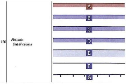
Airspaces in ICAO Annex 4 are visualized using inner fills polygons which may be complex to construct. See the image from the ICAO Annex 4 below.
Figure 1 - ICAO Airspace style
7.1.1.1 Problem
Airspaces have relatively complex visualizations and often large polygons with large number of points.
7.1.1.2 Recommendations
7.1.1.2.1 Visualization
Classification A to D could be achieved by the following example. Instead of having two sets of rules with one for classification A and one for B-D, Recode could be used to set the stroke colors.
<se:Rule>
<se:PolygonSymbolizer> <se:Stroke>
<se:SvgParameter name="stroke-opacity">0.3</se:SvgParameter>
<se:SvgParameter name="stroke-width">4</se:SvgParameter> <se:SvgParameter
name="stroke-linejoin">round</se:SvgParameter> <se:SvgParameter
name="stroke-linecap">square</se:SvgParameter> </se:Stroke>
<se:PerpendicularOffset>-2</se:PerpendicularOffset> </se:PolygonSymbolizer>
<se:PolygonSymbolizer> <se:Stroke>
<se:SvgParameter name="stroke">#160E5B</se:SvgParameter> <se:SvgParameter
name="stroke-opacity">1.0</se:SvgParameter>
<se:SvgParameter name="stroke-width">2</se:SvgParameter> <se:SvgParameter
name="stroke-linejoin">round</se:SvgParameter> <se:SvgParameter
name="stroke-linecap">square</se:SvgParameter> </se:Stroke>
</se:PolygonSymbolizer> </se:Rule>
Classification E can be done in the same way but with a wider and more transparent first stroke and Classification F would be visualized without the transparent stroke altogether. Classification G can be visualized by using a Stroke with "stroke-dasharray" set to a appropriate value and combine it with "stroke-width" to set the "length" of the line. Then apply a PerpendicularOffset to move the dashes.
<se:Rule>
<se:PolygonSymbolizer> <se:Stroke>
<se:SvgParameter name="stroke">Black</se:SvgParameter> <se:SvgParameter
name="stroke-opacity">1.0</se:SvgParameter>
<se:SvgParameter name="stroke-width">2</se:SvgParameter> <se:SvgParameter
name="stroke-linejoin">round</se:SvgParameter> <se:SvgParameter
name="stroke-linecap">square</se:SvgParameter> </se:Stroke>
</se:PolygonSymbolizer> <se:PolygonSymbolizer> <se:Stroke>
<se:SvgParameter name="stroke">Black</se:SvgParameter> <se:SvgParameter
name="stroke-opacity">1.0</se:SvgParameter>
<se:SvgParameter name="stroke-width">5</se:SvgParameter> <se:SvgParameter
<se:SvgParameter name="stroke-dasharray">1,15</se:SvgParameter> </se:Stroke>
<se:PerpendicularOffset>-2</se:PerpendicularOffset> </se:PolygonSymbolizer>
</se:Rule>
7.1.1.2.2 Geometrical complexity
Airspaces are often large polygons, with large number of points, for example when following country borders. This causes large volumes of data to transfer and heavy processing when portraying the information. To address this issue, the geometries would have to be simplified with level-of-detail support, as discussed further in chapter 7.4.2.
7.1.2 Special patterns
7.1.2.1 Problem
ICAO Annex 4 contains styles with fill patterns such as checkerboard or slanted lines, which are complex to achieve.
7.1.2.2 Recommendations
7.1.2.2.1 GraphicFill/Stroke
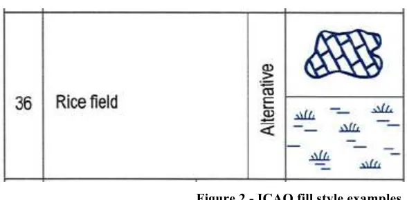
The majority of the complex fill patterns in the ICAO guidelines can simply be defined using raster image tiles in a format that supports transparency. Encoding in SLDs can then easily be achieved using the GraphicFill and GraphicStroke elements from the SE 1.1 specification.
This approach has been validated using Closed Surfaces (Runways) as the case study, see chapter 7.3.1. The validation was performed using two separate FPSs.
7.1.2.2.2 Complex Fills
The following SLD snippet shows the simple encoding that has been used by both implementations to render special patterns to fill area geometry.
<se:PolygonSymbolizer> <se:Geometry>
<ogc:PropertyName>...</ogc:PropertyName> </se:Geometry>
<se:Fill>
<se:GraphicFill> <se:Graphic>
<se:ExternalGraphic>
<se:OnlineResource xlink:href="http://localhost/images/Fills/red_diag.png" xlink:type="simple"/> <se:Format>image/png</se:Format>
</se:ExternalGraphic> </se:Graphic>
</se:PolygonSymbolizer>
7.1.2.2.3 Complex Lines
The following SLD snippet shows the simple encoding that has been used by both implementations to render special patterns to fill area geometry. The Graphic Stroke can be used in this way for line geometry, or for the borders of polygon geometry.
<sld:LineSymbolizer> <sld:Geometry>
<ogc:PropertyName>GEOMETRY</ogc:PropertyName> </sld:Geometry>
<sld:Stroke>
<sld:GraphicStroke> <sld:Graphic>
<sld:ExternalGraphic>
<sld:OnlineResource xlink:href="http://localhost/images/Lines/0716b_magenta.png" xlink:type="simple"/>
<sld:Format>image/png</sld:Format> </sld:ExternalGraphic>
<!-- sets the line width to be 8 pixels, which scales up / down the png file for rendering --> <sld:Size>8</sld:Size>
</sld:Graphic> </sld:GraphicStroke> </sld:Stroke>
</sld:LineSymbolizer>
7.1.2.2.4 GraphicFill/Stroke versus “Pen-Up, Pen-Down”
Figure 2 - ICAO fill style examples
The expressive capability required would not only be a far greater overhead for implementers, with all of the implied issues (limitations of vendor-specific
implementations, misinterpretations of the specification etc.) but would result in the potential for very verbose SLDs. This in itself represents performance implications (network traffic / bandwidth) for heavily used systems.
The obvious disadvantage is that for simpler fill styles, a vector rendering would be much more efficient and hence higher performance could be achieved by the FPS. The hatched pattern suggested for SE 1.2 is a good example.
However, one of the FPSs used to test this approach applies an interesting optimization in this area that could be used by other FPS implementations, particularly when working in a fixed enterprise/domain such as AIM: The FPS can be pre-configured to pair up the URLs of external graphics with well known rendering styles (points / lines / fills).
This optimization enables the software to perform its actual rendering task using its intrinsically high performance vector rendering (in place of the more cumbersome raster tiling). This would allow vendors to optimize their FPS implementations for well known domains, and yet would allow the enterprise community to rely only on the standards when choosing their service providers.
Note: both techniques were shown to work using different FPS software, although no performance testing was undertaken to quantify the performances of the two approaches.
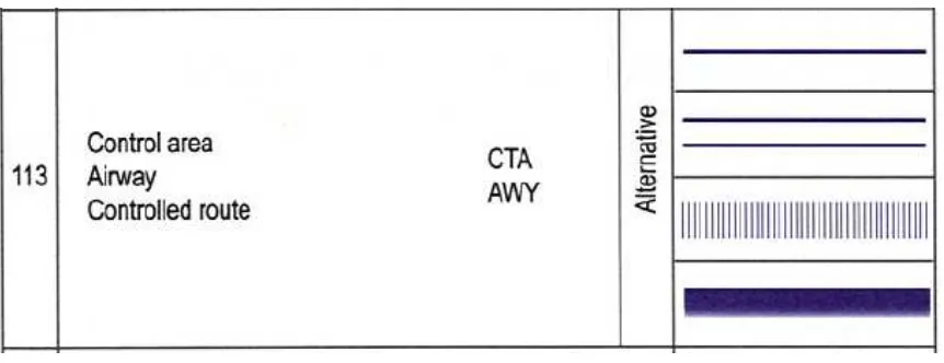
7.1.2.2.5 Translucency within complex line styles
Figure 3 - ICAO ATS line styles
7.1.2.2.6 GraphicFill using inline SVG
Related to the use of a GraphicFill? to achieve complex patterns, it should also be noted that it is possible to use an embedded SVG image. This avoids having external
dependencies in your SLD which makes it easier to exchange. The use of SVG also makes the resulting SLD more readible/editable, as opposed to embedding an BASE64 encoded image.
Below is an example of a RunwayElement? feature type style with an embedded SVG that defines a checkerboard pattern. Note that the SVG can probably be optimized a bit further to reduce its size.
<?xml version='1.0' encoding='UTF-8'?>
<se:FeatureTypeStyle xmlns:se="http://www.opengis.net/se" xmlns:o
gc="http://www.opengis.net/ogc" xmlns:xsd="http://www.w3.org/2001
/XMLSchema" xmlns:sld="http://www.opengis.net/sld" xmlns:gml="htt p://www.opengis.net/gml" xmlns:xlink="http://www.w3.org/1999/xlin
k" xmlns:xsi="
http://www.w3.org/2001/XMLSchema-instance" xsi:schemaLocation="http://www.opengis.net/ogc http://s chemas.opengis.net/filter/1.1.0/filter.xsd http://www.w3.org/2001 /XMLSchema http://www.w3.org/2001/XMLSchema.xsd http://www.opengi s.net/se http://schemas.opengis.net/se/1.1.0/FeatureStyle.xsd htt p://www.opengis.net/sld http://schemas.opengis.net/sld/1.0.0/Styl edLayerDescriptor.xsd http://www.opengis.net/gml http://schemas.o pengis.net/gml/3.1.1/base/gml.xsd http://www.w3.org/1999/xlink ht tp://schemas.opengis.net/xlink/1.0.0/xlinks.xsd " version="1.1.0"
>
<se:Name>RunwayElementType</se:Name>
<se:FeatureTypeName>RunwayElementType</se:FeatureTypeName> <se:Rule>
<se:MinScaleDenominator>0.0</se:MinScaleDenominator> <se:MaxScaleDenominator>INF</se:MaxScaleDenominator> <se:PolygonSymbolizer>
<se:Fill>
<se:GraphicFill> <se:Graphic>
<se:InlineContent encoding="xml">
<svg xmlns="http://www.w3.org/2000/svg" xmlns:cc=
"http://creativecommons.org/ns#" xmlns:sodipodi="http://sodipodi.
sourceforge.net/DTD/sodipodi-0.dtd" xmlns:rdf="
http://www.w3.org/1999/02/22-rdf-syntax-ns#" xmlns:inkscape="http://www.inkscape.org/namespaces/inkscape"
xmlns:svg="http://www.w3.org/2000/svg" xmlns:dc="http://purl.org /dc/elements/1.1/" contentScriptType="text/ecmascript" zoomAndPan
="magnify" contentStyleType="text/css" id="svg2" sodipodi:docname
="checkerboard2.svg" version="1.1" width="32" preserveAspectRatio
="xMidYMid meet" height="32">
<sodipodi:namedview objecttolerance="10" border color="#666666"
inkscape:window-height="968" inkscape:zoom="9.90625" gridtolerance="10" id="named view11" inkscape:current-layer="svg2" inkscape:window-y="
-3" inkscape:cy="17.211356" inkscape:window-x="
-2" inkscape:cx="0.15141956" showgrid="false" guidetolerance="10"
inkscape:pageopacity="0" inkscape:pageshadow="2" inkscape:window-width="1280" pagecolor="#ffffff" borderopacity="1" inkscape:windo w-maximized="1"/>
<defs id="defs4">
<pattern xlink:href="#Checkerboard" xlink:typ e="simple" xlink:actuate="onRequest" patternTransform="matrix(7.6 424715,0,0,7.7030688,4.6949061,239.26733)" id="pattern5237" prese rveAspectRatio="xMidYMid meet" xlink:show="replace"/>
<pattern width="2" patternUnits="userSpaceOnU se" xlink:type="simple" xlink:actuate="onRequest" height="2" patt ernTransform="translate(0,0) scale(10,10)" id="Checkerboard" pres erveAspectRatio="xMidYMid meet" xlink:show="replace">
<rect x="0" y="0" width="1" style="fill:bla ck;stroke:none" height="1" id="rect4549"/>
<rect x="1" y="1" width="1" style="fill:bla ck;stroke:none" height="1" id="rect4551"/>
</pattern> </defs>
<g id="layer1" style="stroke:none" transform="t ranslate(0,-1020.3622)">
<rect x="0.030934934" y="1020.5137" width="32 .241737" style="
<ogc:Literal>1.0</ogc:Literal> </se:SvgParameter>
<se:SvgParameter name="stroke">#000000</se:SvgParameter> <se:SvgParameter name="stroke-width">
<ogc:Literal>1</ogc:Literal> </se:SvgParameter>
</se:Stroke>
</se:PolygonSymbolizer> </se:Rule>
</se:FeatureTypeStyle>
7.1.3 ICAO Restricted airspace styling
7.1.3.1 Problem
Restricted airspaces have a styling which is very complex. See the imge from the ICAO Annex 4 below.
Figure 4 - ICAO Restricted airspace styling
7.1.3.2 Recommendation
The recommended style is not possible to achieve in an SLD today. Technically it would require support for using a GraphicFill as mentioned above, but only within a bufferzone inside a polygon.
Repeating a symbol along the line is another way to achive a similar presentation, however this causes issues primarily in angles, where the visualization will get cluttered. An example of some of the problems can be seen below.
Figure 5 - Line with repeated symbol
Figure 6 - Restricted airspaces alternate visualization
7.1.4 Airways
7.1.4.1 Problem
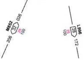
The symbol for enroute airways in ICAO Annex 4 is simply a black line, but Aneex 4 chapter 7.9.3.1.1 the required components for ATS are listed. For ATS routes in en-route flight for example designators and the track in both directions should be displayed, together with minimum heights and distances between significant or reporting points.
7.1.4.2 Recommendations
Here are two examples of how that information could be visualized.
Figure 7 - Airway symbol example
The first image shows an example with two directions and the second an airway with one direction.
With SE 1.1.0 this is be hard to accomplish. In SE 1.2 there are some proposed changes that probably could be used. A CompositeGraphic used in a GraphicStroke could accomplish some of the desired visualization and with RelativeOrientation set to "line" the symbol would be rotated along the line.
What remains is that the line should be clipped by the bound box of the
resulting length is hard to know, wouldn't it be better to have an element "ClipLine" which tells that the line should be clipped by the graphics bounding box. A Padding or gap element is probably needed as well to be able to extend the clip area. This approach makes the configuration simpler but perhaps it requires a more complex implementation. An alternative could be to use the CompoundStroke. The use of PreGap and PostGap seems a little awkward but perhaps I'm only misinterpreting it. How can PreGap and PostGap be used in CompoundStroke to create a gap? Explanatory text from the document "The PreGap tells how far to advance along the line before starting to plot content and the PostGap tells how far from the end of the line to stop all plotting."
7.1.5 Label deconfliction
7.1.5.1 Problem
Aeronautical data typically contains large amounts of data which are likely to be hard or impossible to create a readable visualization from without label deconfliction. Different data may have different importance when doing that so rules, priorities or hints to deconfliction may be necessary to enable such functionality in clients.
7.1.5.2 Recommendations
Label deconfliction is not supported in SE and likely far too complex to support in any detail. It should rather be up to the clients to support this, but in order to do so the client needs to know what it can and cannot do. Typically in regards to what features can be hidden or how much a label can be displaced and still create a good enough result. To support this deconfliction attributes will be necessary in SLD. There is a change request regarding this issue CR 11-023 but it is only for text labels. More complex symbols like a CompositeGraphic could also need deconfliction and organizing and an additional change proposal is necessary.
The proposal is to add a new element Deconfliction. The element CanBeRemoved in Deconfliction determines if the symbol can be removed if it cannot be placed without overlapping another symbol in the same layer. The element Priority should work as in CR 11-023 and is used to set importance of a symbol. The priority could be set with a number directly or by fetching a value from a property.
<xsd:element name="Deconfliction"> <xsd:complexType>
<xsd:sequence>
<xsd:element ref="se:CanBeRemoved" minOccurs="0"/> <xsd:element ref="se:Priority" minOccurs="0"/> </xsd:sequence>
</xsd:complexType> </xsd:element>
<xsd:element name="CanBeRemoved" type="xsd:boolean"/>
The possibility to use deconfliction is needed on
PointSymbolizer? and TextSymbolizer? and they should be modified to look like this.
<xsd:element name="PointSymbolizer" substitutionGroup="se:Symbolizer"> <xsd:complexType>
<xsd:complexContent>
<xsd:extension base="se:SymbolizerType"> <xsd:sequence>
<xsd:element ref="se:Geometry" minOccurs="0"/> <xsd:element ref="se:UnitOfMeasure" minOccurs="0"/> <xsd:element ref="se:Transform" minOccurs="0"/> <xsd:element ref="se:Graphic"/>
<xsd:element ref="se:Deconfliction" minOccurs="0"/> </xsd:sequence>
</xsd:extension> </xsd:complexContent> </xsd:complexType> </xsd:element>
<xsd:element name="TextSymbolizer" substitutionGroup="se:Symbolizer"> <xsd:complexType>
<xsd:complexContent>
<xsd:extension base="se:SymbolizerType"> <xsd:sequence>
<xsd:element ref="se:Geometry" minOccurs="0"/> <xsd:element ref="se:UnitOfMeasure" minOccurs="0"/>
<xsd:element ref="se:PerpendicularOffset" minOccurs="0"/> <xsd:element ref="se:Transform" minOccurs="0"/>
<xsd:element ref="se:Label" minOccurs="0"/>
<xsd:element ref="se:Deconfliction" minOccurs="0"/> </xsd:sequence>
</xsd:extension> </xsd:complexContent> </xsd:complexType> </xsd:element>
The current suggestion of the Deconfliction element is a bare minimum and it probably needs to be extended to give more control over the deconflition behavior. Perhaps the ability to specify a deconfliction algorithm (e.g. 'explode on click') would be useful. A code-list of well known deconfliction algorithms could be identified.
7.2 Data dependent
7.2.1 Specifying geometries in symbolizers
7.2.1.1 Problem
Symbolizers use xpath expressions to point to the geometry that they want to display.
7.2.1.2 Recommendations
Different implementers tend to support different xpaths in this element, so we need to agree on a few best practices:
Do not specify a geometry in case the feature only has one tag in which the geometry can be defined, this allows a bit more freedom for the implementation, which can be useful for instance in airspaces. (Airspaces can have multiple geometry components that need to be combined.)
Always point to the actual geometry, not to the property around it. For instance AirportHeliportTimeSlice /ARP/ElevatedPoint, not AirportHeliportTimeSlice /ARP.
Avoid the use of '//', even though this is a convenient shortcut, since it does force the implementation to do a search through the entire feature.
7.2.2 Portrayal of hierarchical data
7.2.2.1 Problem
The AIXM model contains many feature types of a hierarchical nature. There is a need to encode styles for such features using rule conditions that evaluate the properties of the features’ nested children.
7.2.2.2 Recommendations
The AIXM model contains many feature types of a hierarchical nature. There is a need to encode styles for such features using rule conditions that evaluate the properties of the features’ nested children.
A change request entitled SE Symbolizer and Rule for styling of nested child objects has been raised to allow different style to be applied to nested children based on the
childrens’ properties. See Annex C for more details on the change request.
7.2.3 Portrayal of relational data
7.2.3.1 Problem
Many of AIXM’s feature types are conceptually composite types. The AIXM model tends to specify uni-directional relationships between features and their component features. Unfortunately the navigable direction of such relationships also tends to be in the opposite direction to that required for portrayal.
7.2.3.2 Recommendations
In order to portray AIXM data such as the examples below, it is recommended that the WFS services behind the FPS should be either an Xlink WFS (WFS 1.1.0) or be WFS 2.0.0 compliant.
This recommendation and others are explored in the airport portrayal example below and in Annex A.
7.2.3.3 Example: Airport Portrayal
The Aeronautical Charts (Annex 4 to the Convention on International Civil Aviation) calls for an abbreviated form which may be in association with Aerodrome symbols. This abbreviated form looks like this:
The labels displayed rely on properties of the airport’s components, for example the length of the longest runway must be obtained by evaluating all of the airport’s runways. The problem is that an SLD cannot define a rule that can access the associated runways in terms of the airport’s properties. In short, the Airport does not contain a reference to its runways, so the SLD cannot access the “length”. We can see that the required links are missing from the Airport by inspection of the example GML Airport feature below.
<aixm:AirportHeliport gml:id="gmlID102079" xmlns:aixm="http://www.aixm.aero/schema/5.1" xmlns:gml="http://www.opengis.net/gml/3.2">
<gml:identifier codeSpace="http://www.comsoft.aero/cadas-aimdb/caw"> 000AB061-864F-4E7C-94B6-D769C7238AC2</gml:identifier>
<aixm:timeSlice>
<gml:validTime>
<gml:TimePeriod gml:id="gmlID102142">
<gml:beginPosition>2000-01-01T00:00:00.000Z</gml:beginPosition> <gml:endPosition>9999-12-31T23:59:59.000Z</gml:endPosition> </gml:TimePeriod>
</gml:validTime>
<aixm:interpretation>BASELINE</aixm:interpretation> <aixm:sequenceNumber>1</aixm:sequenceNumber> <aixm:correctionNumber>0</aixm:correctionNumber> <aixm:featureLifetime>
<gml:TimePeriod gml:id="gmlID102143">
<gml:beginPosition>2000-01-01T00:00:00.000Z</gml:beginPosition> <gml:endPosition>9999-12-31T23:59:59.000Z</gml:endPosition> </gml:TimePeriod>
</aixm:featureLifetime>
<aixm:designator xmlns:xsi="http://www.w3.org/2001/XMLSchema-instance" xsi:nil="true"/> <aixm:name>CURTIS MUNI</aixm:name>
<aixm:locationIndicatorICAO xmlns:xsi="http://www.w3.org/2001/XMLSchema-instance" xsi:nil="true"/>
<aixm:designatorIATA xmlns:xsi="http://www.w3.org/2001/XMLSchema-instance" xsi:nil="true"/> <aixm:type>AH</aixm:type>
<aixm:certifiedICAO xmlns:xsi="http://www.w3.org/2001/XMLSchema-instance" xsi:nil="true"/> <aixm:privateUse>NO</aixm:privateUse>
<aixm:controlType xmlns:xsi="http://www.w3.org/2001/XMLSchema-instance" xsi:nil="true"/> <aixm:fieldElevation xmlns:xsi="http://www.w3.org/2001/XMLSchema-instance" xsi:nil="true"/> <aixm:fieldElevationAccuracy xmlns:xsi="http://www.w3.org/2001/XMLSchema-instance" xsi:nil="true"/>
<aixm:verticalDatum xmlns:xsi="http://www.w3.org/2001/XMLSchema-instance" xsi:nil="true"/> <aixm:magneticVariation xmlns:xsi="http://www.w3.org/2001/XMLSchema-instance" xsi:nil="true"/> <aixm:magneticVariationAccuracy xmlns:xsi="http://www.w3.org/2001/XMLSchema-instance" xsi:nil="true"/>
<aixm:dateMagneticVariation xmlns:xsi="http://www.w3.org/2001/XMLSchema-instance" xsi:nil="true"/>
<aixm:magneticVariationChange xmlns:xsi="http://www.w3.org/2001/XMLSchema-instance" xsi:nil="true"/>
<aixm:referenceTemperature xmlns:xsi="http://www.w3.org/2001/XMLSchema-instance" xsi:nil="true"/>
<aixm:altimeterCheckLocation xmlns:xsi="http://www.w3.org/2001/XMLSchema-instance" xsi:nil="true"/>
<aixm:secondaryPowerSupply xmlns:xsi="http://www.w3.org/2001/XMLSchema-instance" xsi:nil="true"/>
<aixm:windDirectionIndicator xmlns:xsi="http://www.w3.org/2001/XMLSchema-instance" xsi:nil="true"/>
<aixm:landingDirectionIndicator xmlns:xsi="http://www.w3.org/2001/XMLSchema-instance" xsi:nil="true"/>
<aixm:transitionAltitude xmlns:xsi="http://www.w3.org/2001/XMLSchema-instance" xsi:nil="true"/> <aixm:transitionLevel xmlns:xsi="http://www.w3.org/2001/XMLSchema-instance" xsi:nil="true"/> <aixm:lowestTemperature xmlns:xsi="http://www.w3.org/2001/XMLSchema-instance"
xsi:nil="true"/>
<aixm:abandoned xmlns:xsi="http://www.w3.org/2001/XMLSchema-instance" xsi:nil="true"/> <aixm:certificationDate xmlns:xsi="http://www.w3.org/2001/XMLSchema-instance" xsi:nil="true"/> <aixm:certificationExpirationDate xmlns:xsi="http://www.w3.org/2001/XMLSchema-instance" xsi:nil="true"/>
<aixm:contaminant xmlns:xsi="http://www.w3.org/2001/XMLSchema-instance" xsi:nil="true"/> <aixm:servedCity>
</aixm:City> </aixm:servedCity>
<aixm:responsibleOrganisation xmlns:xsi="http://www.w3.org/2001/XMLSchema-instance" xsi:nil="true"/>
<aixm:ARP>
<aixm:ElevatedPoint gml:id="gmlID102145" srsName="urn:ogc:def:crs:OGC:1.3:CRS84"> <gml:pos>-100.47275 40.63875</gml:pos>
</aixm:ElevatedPoint> </aixm:ARP>
<aixm:aviationBoundary xmlns:xsi="http://www.w3.org/2001/XMLSchema-instance" xsi:nil="true"/> <aixm:altimeterSource xmlns:xsi="http://www.w3.org/2001/XMLSchema-instance" xsi:nil="true"/> <aixm:contact xmlns:xsi="http://www.w3.org/2001/XMLSchema-instance" xsi:nil="true"/>
<aixm:availability>
<aixm:AirportHeliportAvailability gml:id="gmlID102152"> <aixm:operationalStatus>NORMAL</aixm:operationalStatus> <aixm:usage>
<aixm:annotation xmlns:xsi="http://www.w3.org/2001/XMLSchema-instance" xsi:nil="true"/> </aixm:AirportHeliportTimeSlice>
</aixm:timeSlice> </aixm:AirportHeliport>
When we inspect an example of a Runway, we can see the link to the airport feature:
<aixm:Runway gml:id="gmlID67205" xmlns:aixm="http://www.aixm.aero/schema/5.1" xmlns:gml="http://www.opengis.net/gml/3.2">
<gml:identifier codeSpace="http://www.comsoft.aero/cadas-aimdb/caw"> 00AB92E2-9B9B-48F7-AD0A-79FD7639F4A5</gml:identifier>
<aixm:timeSlice>
<aixm:RunwayTimeSlice gml:id="gmlID67206"> <gml:validTime>
<gml:TimePeriod gml:id="gmlID67207">
<gml:beginPosition>2000-01-01T00:00:00.000Z</gml:beginPosition> <gml:endPosition>9999-12-31T23:59:59.000Z</gml:endPosition> </gml:TimePeriod>
</gml:validTime>
<aixm:interpretation>BASELINE</aixm:interpretation> <aixm:sequenceNumber>1</aixm:sequenceNumber> <aixm:correctionNumber>0</aixm:correctionNumber> <aixm:featureLifetime>
<gml:TimePeriod gml:id="gmlID67208">
</aixm:featureLifetime>
<aixm:designator>17/35</aixm:designator>
<aixm:type xmlns:xsi="http://www.w3.org/2001/XMLSchema-instance" xsi:nil="true"/> <aixm:nominalLength xmlns:xsi="http://www.w3.org/2001/XMLSchema-instance" xsi:nil="true"/>
<aixm:lengthAccuracy xmlns:xsi="http://www.w3.org/2001/XMLSchema-instance" xsi:nil="true"/>
<aixm:nominalWidth xmlns:xsi="http://www.w3.org/2001/XMLSchema-instance" xsi:nil="true"/>
<aixm:widthAccuracy xmlns:xsi="http://www.w3.org/2001/XMLSchema-instance" xsi:nil="true"/>
<aixm:widthShoulder xmlns:xsi="http://www.w3.org/2001/XMLSchema-instance" xsi:nil="true"/>
<aixm:lengthStrip uom="M">2255.8248</aixm:lengthStrip> <aixm:widthStrip uom="M">30.48</aixm:widthStrip>
<aixm:lengthOffset xmlns:xsi="http://www.w3.org/2001/XMLSchema-instance" xsi:nil="true"/>
<aixm:widthOffset xmlns:xsi="http://www.w3.org/2001/XMLSchema-instance" xsi:nil="true"/>
<aixm:abandoned xmlns:xsi="http://www.w3.org/2001/XMLSchema-instance" xsi:nil="true"/>
<aixm:surfaceProperties xmlns:xsi="http://www.w3.org/2001/XMLSchema-instance" xsi:nil="true"/>
<aixm:associatedAirportHeliport xlink:href=" http://www.comsoft.aero/cadas- aimdb/generated#xpointer(//AirportHeliport[gml:identifier=000AB061-864F-4E7C-94B6-D769C7238AC2'])" xmlns:xlink="http://www.w3.org/1999/xlink"/>
<aixm:overallContaminant xmlns:xsi="http://www.w3.org/2001/XMLSchema-instance" xsi:nil="true"/>
<aixm:annotation xmlns:xsi="http://www.w3.org/2001/XMLSchema-instance" xsi:nil="true"/>
<aixm:areaContaminant xmlns:xsi="http://www.w3.org/2001/XMLSchema-instance" xsi:nil="true"/>
</aixm:RunwayTimeSlice> </aixm:timeSlice>
</aixm:Runway>
In order to portray AIXM data such as the examples above, it is recommended that the WFS services behind the FPS should be either an Xlink WFS (WFS 1.1.0) or be WFS 2.0.0 compliant. The onus will then be on the WFS (with appropriate instruction from the FPS regarding Xlink resolution) to ensure that the results of a query include not only the requested features, but any related features that are referenced (xlinked) by the requested features, which as mentioned above may well be required / used by the SLD.
For example with a WFS 2.0.0 compliant WFS, we can use the resolve and resolveDepth parameters of the GetFeature query to ensure that all of the GML content required for portrayal of this airport and runway length is included in the result:
xmlns:gml="http://www.opengis.net/gml/3.2" <wfs:Query typeNames="Runway">
<wfs:PropertyName>aixm:timeSlice/aixm:RunwayTimeSlice/aixm:lengthStrip</wfs:PropertyName> <wfs:PropertyName resolve="all"
resolveDepth="1">aixm:timeSlice/aixm:RunwayTimeSlice/aixm:associatedAirportHeliport</wfs:Property Name>
The above query yields the following result with the airport definition included inline:
<aixm:Runway gml:id="gmlID67205" xmlns:aixm="http://www.aixm.aero/schema/5.1" xmlns:gml="http://www.opengis.net/gml/3.2">
<aixm:timeSlice>
<aixm:RunwayTimeSlice gml:id="gmlID67206">
<aixm:lengthStrip uom="M">2255.8248</aixm:lengthStrip> <aixm:associatedAirportHeliport>
<aixm:AirportHeliport gml:id="gmlID102079"
xmlns:aixm="http://www.aixm.aero/schema/5.1" xmlns:gml="http://www.opengis.net/gml/3.2"> <gml:identifier codeSpace="
http://www.comsoft.aero/cadas-aimdb/caw">000AB061-864F-4E7C-94B6-D769C7238AC2</gml:identifier> <!-- contents omitted for brevity-->
</aixm:AirportHeliport> </aixm:associatedAirportHeliport> </aixm:RunwayTimeSlice>
</aixm:timeSlice> </aixm:Runway>
Using the CompositeChildSymbolizer, this allows an SLD to render the airport geometry as well as a label containing the runway length. There is one remaining problem with this however in that the SLD would need to define a FeatureTypeStyle for the
RunwayElement to achieve this portrayal.
Logically speaking the composition is the other way around; the Runway forms part of the Airport, not vice versa. But more importantly, the style may need to account for more than just the component Runways of an Airport; it may wish to create rules based on the properties of an associated Apron or RadarSystem.
Therefore, it is further recommended that the “reverse associations” extension of AIXM 5.1 be employed for the purposes of defining AIXM portrayal SLDs.
As a final comment, future versions of the AIXM UML Application Schema model may want to consider specifying bi-directional associations where applicable in the aerospace domain. Note that this comment applies to the AIXM conceptual model (i.e. Platform independent UML model). The two-way navigability of the relationships could then be reflected in derived “encoding models” such as the GML application schema. The encoding model for data storage, in a database for example, would not need to be affected.
See also Annex A.
7.2.4 AIXM Temporality
7.2.4.1 Problem
The temporality model of AIXM 5 is a problem, since it would typically require filtering of features based on temporal properties.
7.2.4.2 Recommendations
The temporality aspect has not been explored to any great depths within the portrayal project but a few recommendations can still be pointed out:
Some temporal filtering can be performed from within an SLD document but should preferably be performed at the WFS-level, to greatly simplify the SLDs, reduce the workload for the portrayal service and to reduce the amount of data transferred between the data provider and portrayal service. Querying a WFS for AIXM-data is covered in further detail in OGC 11-073 - OWS-8 WFS Guidance for AIXM.
It is however possible to perform time dependent styling as explored in the SAA-pilot project. This showed that a requirement for time dependent styling is the need for an evaluateDuring function, which is also covered in the WFS guidance document.
7.3 Portrayal of status information
7.3.1 Closed/unserviceable features
7.3.1.1 Problem
The ICAO Annex 4 contains no recommendation on how to portray availability information such as closed runways and taxiways, unserviceable navaids etc.
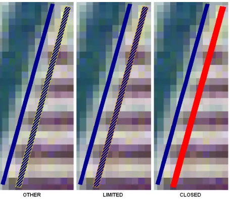
7.3.1.2 Recommendations – Surface Availability (Runways/Taxiways)
especially important when viewing data at higher zoom levels as a hatching pattern becomes very indistinct as can be seen in Figure 9 and Figure 10.
The status of the surface will be retrieved from the availability element using the following XPath:
aixm:timeSlice/aixm:RunwayElementTimeSlice/aixm:availability/aixm:ManoeuvringAre aAvailability/aixm:operationalStatus and the constant can have four different values: 'NORMAL','LIMITED', 'CLOSED' and 'OTHER'.
We suggest that surfaces with status 'CLOSED' be visualized with a solid red fill and the 'LIMITED' and 'OTHER' availability, be visualized with the hatched pattern in amber and yellow respectively as to avoid the stronger danger indication that red provides. Pros of using a solid color is of course that it is a simpler visualization and red will make it very clear that the surface is unavailable. A con of using colors as indicators is that they make it hard to distinguish between open and closed surfaces in black and white.
7.3.1.2.1 Hatching pattern
The hatched fill pattern can be achieved using raster image tiles in a format that supports transparency. Encoding in SLDs can then easily be achieved using the GraphicFill? element from the SE 1.1 specification.
Optionally a HatchedFill keyword is being considered for SE 1.2. According to that schema, a hatching fill would look like:
<HatchedFill uom="urn:ogc:def:uom:se::px">
<Stroke>SE stroke parameters such as color and line width</Stroke> <Angle>45</Angle>
<!--Default is 45 so this can be dropped--> <Distance>8</Distance>
<!--Distance in pixels, should we use meters?--> </HatchedFill>
One minor problem with a hatching pattern is that viewing a runway with bearing 45/225 with north up would not visualize the status as well, since the hatch pattern would be parallel with the runway. Ideal would be a hatch angle which is relative to the runway bearing. But unfortunately, the runway elements themselves do not contain this information. It is available in the runway direction, but there is no clear path from the elements to the direction. For further discussion on this type of problems, see Annex A.
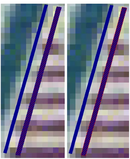
7.3.1.2.2 Outline
The outline should be set to the same color as the hatchings and will help to distinguish between runways of differing status more clearly. This is particularly noticeable when the view is not zoomed in such that a single runway fills the screen / viewing panel.
Figure 9 — Close-up of hatched filled Runway with (Right) and without (Left) additional outline
Figure 10 — Zoomed out view of hatched filled Runway with (Right) and without (Left) additional outline
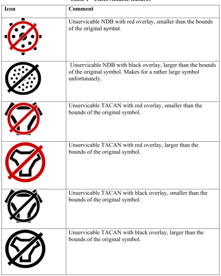
7.3.1.3 Recommendations – Unserviceable features
Table 1 - Unserviceable features
Icon Comment
Unservicable NDB with red overlay, smaller than the bounds of the original symbol.
Unservicable NDB with black overlay, larger than the bounds of the original symbol. Makes for a rather large symbol
unfortunately.
Unservicable TACAN with red overlay, smaller than the bounds of the original symbol.
Unservicable TACAN with red overlay, larger than the bounds of the original symbol.
Unservicable TACAN with black overlay, smaller than the bounds of the original symbol.
Unservicable TACAN with black overlay, larger than the bounds of the original symbol.
7.3.2 Contamination
7.3.2.1 Problem
The ICAO Annex 4 contains no recommendation on how to portray contamination of surfaces, such as runways and taxiways.
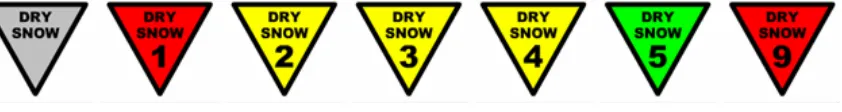
7.3.2.2 Recommendations
In the digital SNOWTAM trial of Eurocontrol a triangular icon was used to indicate contaminations. The icon had a fill color based on friction estimate, and also showed the friction estimate together with the type of contaminant. Next to the icon, the extent of the upper contaminant layer was also visualized with a fill color based on contamination type. Se figures below.
Figure 12 — SNOWTAM symbols.
Figure 2 — Multiple layer contamination icon.
Contaminations are modeled as sub-objects of features, similar to light elements or markings. This means that we also have to use a hierarchical symbolizer.
7.3.2.2.1 Contamination data
Even if a surface has two or more layers with different horizontal projections, they should still be modelled as one SurfaceContamination, with several SurfaceContaminationLayer, but with different associated ElevatedSurface features. That's because there is only one observationTime. I this case a "multiple layer" symbol should be placed in the
7.3.2.2.2 Contamination Icon
The SE 1.2 SWG defines an update to how graphics can be defined in SLD. This can be used for the contamination icon. Note that this icon is supposed to be wrapped in a hierarchical symbolizer, so the xpaths are relative to an AbstractSurfaceContamination object.
The following is the outline of the SE specification for an icon, some blanks still need to be worked out:
<CompositeGraphic>
<PointTextGraphic>
<PointPosition><X>...</X><Y>...</Y></PointPosition>
<PointLabel>aixm:layer/aixm:SurfaceContaminationLayer/ aixm:type</PointLabel>
</PointTextGraphic> <PointTextGraphic>
<PointPosition><X>...</X><Y>...</Y></PointPosition>
<PointLabel>aixm:frictionEstimation</PointLabel><!--convert estimate to number--> </PointTextGraphic>
<MarkGraphic>
<WellKnownName>TRIANGLE</WellKnowName>
<Fill>convert friction coefficient/estimate to color</Fill>
<Stroke>thick black line</stroke> </MarkGraphic>
</CompositeGraphic>
7.3.2.2.3 Contamination Icon in SE 1.1.0
How can the contamination symbol be visualized in SE 1.1.0? This is a skeleton of a possible solution.
<!-- Contamination main symbol visualization --> <se:PointSymbolizer>
<se:Graphic> <se:Mark>
</se:Fill> </se:Mark>
<se:Size>8.0</se:Size>
<se:Rotation>180</se:Rotation> </se:Graphic>
</se:PointSymbolizer> <se:TextSymbolizer> <se:Label>
<!-- Recode into a number. Is that possible here? --> <se:Recode fallbackValue="UNDEFINED">
<LookupValue>
<ogc:PropertyName>aixm:frictionEstimation</ogc:PropertyName >
</LookupValue> ...
</se:Label> </se:TextSymbolizer> <se:TextSymbolizer> <se:Label>
aixm:layer/aixm:SurfaceContaminationLayer/aixm:type<ogc:Pro pertyName></ogc:PropertyName>
</se:Label>
</se:TextSymbolizer>
7.4 Enterprise Considerations
As with any system that migrates to a computerized environment, it is likely that new requirements and use cases will be formed, driven by the flexibility and power offered by automated systems.
7.4.1 Algorithmic Rules
7.4.1.1 Problem
As the symbology business rules evolve, they are likely to include conditions based on more abstract queries of other feature types. For example, there may come a need to render a feature (let’s say a runway) based on whether it intersects with the geometry of another feature (let’s say an airspace that is closed due to volcanic ash). SLD does not allow the encoding of queries / conditions of this nature.
7.4.1.2 Option 1
Either the SE spec may need to consider extension in this area, or the wider system will need to place the responsibility for the necessary filtering query elsewhere. The
pragmatic way forward could depend on the complexity of the required queries. In any case, some recommendations or guidelines for the AIM community might be desirable. For example a portal viewing an area of interest might need to create the required
and then fire off separate queries to retrieve affected and unaffected runways (by filtering based on the geometry retrieved from “affecting” airspaces). The portal would then ask the FPS to render a layer with affected runways with a very simple SLD, and then another layer with unaffected runways, again with a very simple SLD. In this way the portal (or more likely one of its application servers) would then own the domain specific business rules that cannot currently be encoded in an SLD.
One potential disadvantage of this approach is that geometries would need to be extracted by a portal component and embedded into SLDs for an FPS request. These geometries can be large and cumbersome to pass back and forth for such a transaction.
Of course allowing the SLD to specify rules / conditions of this nature would be a powerful extension to the standard and provide strong support to such a system.
7.4.1.3 Option 2 - Recommended
The suggested solution is an extension to the Rule element that allows multiple feature types to be specified. This would be semantically similar to the CSW specification. The existing Filter Encoding 2.0 specification would not need to change however the SE specification would need to define the semantic usage of the filter in this circumstance. The example below is an extract from 07-110r4 CSW-ebRIM Registry Service (section 10.2.3) shows a similar requirement being addressed by the CSW specification.
<csw:Query typeNames="wrs:ExtrinsicObject rim:Association_a1">
<csw:ElementSetName typeNames="wrs:ExtrinsicObject">full</csw:ElementSetName> <csw:Constraint version="1.1.0">
<ogc:Filter> <ogc:And>
<ogc:PropertyIsEqualTo>
<ogc:PropertyName>$a1/@associationType</ogc:PropertyName>
<ogc:Literal>urn:ogc:def:ebRIM-AssociationType:OGC:OperatesOn</ogc:Literal> </ogc:PropertyIsEqualTo>
<ogc:PropertyIsEqualTo>
<ogc:PropertyName>$a1/@sourceObject</ogc:PropertyName>
<ogc:Literal>urn:uuid:86084c6a-292f-4687-bf52-aef49b5ff2d6</ogc:Literal> </ogc:PropertyIsEqualTo>
<ogc:PropertyIsEqualTo>
<ogc:PropertyName>wrs:ExtrinsicObject/@id</ogc:PropertyName> <ogc:PropertyName>$a1/@targetObject</ogc:PropertyName> </ogc:PropertyIsEqualTo>
<ogc:PropertyIsEqualTo>
<ogc:PropertyName>wrs:ExtrinsicObject/@objectType</ogc:PropertyName> <ogc:Literal>urn:ogc:def:ebRIM-ObjectType:OGC:Dataset</ogc:Literal> </ogc:PropertyIsEqualTo>
</ogc:And> </ogc:Filter> </csw:Constraint> </csw:Query>
“FeatureTypeNames”. By applying the same semantics as the CSW example above, we would get something like this:
<se:FeatureTypeStyle>
<se:FeatureTypeNames>aixm:RunwayElement aixm:Airspace<se:FeatureTypeNames> <se:Rule>
The semantic meaning of the above is to apply the symbolizers to “all paved runways within forbidden airspaces”.
7.4.2 Delineations
Another potential evolution in portrayal requirements is that of “level of detail”. Of course, with a digitally displayed chart, the ease at which the user can change the zoom / scale calls for well defined portrayal behaviors for doing so. These behaviors are likely to be specific to the function of the particular type of digital chart. However, they are also likely to involve the issue of the applicability of features’ geometries at different scales. This brings us to delineation of the geometry. When a user is zoomed in to a close view of runways and airports, they may reasonably expect to see the detailed polygonal geometry of the features. However, when zoomed out to a much larger “overview” scale covering a vast area, (for example North America) they may still wish to see the locations of runways or airports. At this scale though, it would probably be more appropriate to display the same features using point symbols rather than polygonal geometry. The polygonal geometry may well be invisible at this scale; at world scale the extent of a runway on a digital display could be less than a pixel (depending on the resolution of the display medium).
the conditions for its rules based on the delineation of the geometry. An example of an existing implementation of this extension to the SE specification is displayed below:
<Rule>
<ogc:PropertyIsEqualTo>
<ogc:Function name="geometryType">
<ogc:PropertyName>geom</ogc:PropertyName>
</ogc:Function>
<ogc:Literal>Point</ogc:Literal>
</ogc:PropertyIsEqualTo>
<PointSymbolizer>
...
</PointSymbolizer> </Rule>
An extension to the SE specification should be considered in order to allow Rules to assess the type of geometry before applying symbolizers. The example above is clearly proprietary, and yet has cross-domain application. It would be a useful capability to add.
Alternatively, to address the simple case above, the SLD itself could be used to
approximate the geometry using the polygons’ centroid or centre of bounding box (this choice would need to be controllable from within the SLD). The scales could then be encoded in the SLD using existing constructs (MinScaleDenominator /
MaxScaleDenominator) to control the level of detail trigger ranges.
7.4.2.1 Centre of Line and Polygon geometries - recommendation
When a PointSymbolizer is used with a Polygon or Line geometry, the specification says: “In this case, if a line, polygon, or raster geometry is used with this Symbolizer, then the semantic is to use the centroid of the geometry, or any similar representative point.” It is recommended that a simple extension is made to the PointSymbolizer to
disambiguate its usage under these circumstances. Furthermore, the choice of “centre-of” algorithm should also be a controllable aspect of the SLD. It should allow for centroid, centre of bounding box, and for polygons a flag to force the resultant point to fall inside the polygon (consider a moon crescent shaped polygon)
Annex A
- Aviation Portrayal based on Directional Associations in AIXM
1 Introduction
1.1 Purpose and Scope
This technical note has been produced by Envitia to summarise some of the issues encountered when applying the OGC Symbology Encoding (SE) to the area of aviation portrayal. In particular, it concentrates on the issue of portrayal rules that are dependent on associations between feature types in the AIXM conceptual model, but which are not realised explicitly via GML properties within the AIXM GML application schema. This report is the result of ongoing research by Envitia within the OGC OWS-8 Aviation Thread [6]. The issue with AIXM associations can be traced to specific requirements in the ICAO portrayal specifications that were studied in OWS-8 [4].
Section 2 describes the problem space in more detail, while Section 3 proposes some solutions.
1.2 Abbreviations
AIXM Aeronautical Information Exchange Model
Envitia Envitia Ltd
EUROCONTROL European Organisation for the Safety of Air Navigation FAA Federal Aviation Administration
FPS Feature Portrayal Service
GML Geography Markup Language
ICAO International Civil Aviation Organization ISO International Organization for Standardization ISO/TC ISO / Technical Committee
OGC Open Geospatial Consortium
OWS OGC Web Services
SE Symbology Encoding
UML Unified Modelling Language
XML Extensible Markup Language
XSD XML Schema
1.3 References and Supporting documents
The following documents are referenced by, or are directly relevant to, this document: 1. AIXM Conceptual Model, version 4.5, EUROCONTROL, 2007
2. AIXM Conceptual Model, version 5.1, FAA, EUROCONTROL, 2010 3. AIXM XML Schema, version 5.1, FAA, EUROCONTROL, 2010
4. Convention on International Civil Aviation, Annex 4 – Aeronautical Charts, 11th Edition, ICAO, 2009
5. ISO 19136:2007, Geographic information – Geography Markup Language (GML). 6. OGC OWS-8 Engineering Report - Guidelines for ICAO portrayal using SLD/SE, OGC, in preparation, 2011
7. OGC 05-077r4, Symbology Encoding Implementation Specification, v.1.1.0, 2006 8. OGC 05-078r4, Styled Layer Descriptor profile of the Web Map Service