BACHELOR THESIS AND COLLOQUIUM
–
ME 141502
FIRE RISK ASSESSMENT OF TERMINAL LPG
SEMARANG
Thariq Arafatul Akbar
NRP 4213 101 025
Supervisor
A.A.B. Dinariyana D.P., S.T. MES. Ph.D.
Ir. Alam Baheramsyah, M.Sc.
DEPARTMENT OF MARINE ENGINEERING
Faculty of Marine Technology
Institut Teknologi Sepuluh Nopember
Surabaya
a
BACHELOR THESIS AND COLLOQUIUM
–
ME 141502
FIRE RISK ASSESSMENT OF TERMINAL LPG
SEMARANG
Thariq Arafatul Akbar
NRP 4213 101 025
Supervisor
A.A.B. Dinariyana D.P., S.T. MES. Ph.D.
Ir. Alam Baheramsyah, M.Sc.
DEPARTMENT OF MARINE ENGINEERING
Faculty of Marine Technology
Institut Teknologi Sepuluh Nopember
Surabaya
i
APPROVAL FORM
FIRE RISK ASSESSMENT OF TERMINAL LPG SEMARANG
BACHELOR THESIS
Submitted to Comply One of the Requirement to Obtain a Bachelor of Engineering Degree
On
Reliability, Availability, Management, and Safety (RAMS) Laboratory S-1 Programe Department of Marine Engineering
Faculty of Marine Technology Institut Teknologi Sepuluh Nopember
Prepared by:
THARIQ ARAFATUL AKBAR Nrp. 4213 101 025
Acknowledged by Bachelor Thesis Supervisor:
1. A.A.B. Dinariyana D.P., S.T. MES. Ph.D. ... NIP. 1975 1006 2002 12 1003
2. Ir. Alam Baheramsyah, M.Sc. ... NIP. 1976 0310 2000 03 1001
ii
iii
APPROVAL FORM
FIRE RISK ASSESSMENT OF TERMINAL LPG SEMARANG
BACHELOR THESIS
Submitted to Comply One of the Requirement to Obtain a Bachelor of Engineering Degree
On
Reliability, Availability, Management, and Safety (RAMS) Laboratory S-1 Programe Department of Marine Engineering
Faculty of Marine Technology Institut Teknologi Sepuluh Nopember
Prepared by:
THARIQ ARAFATUL AKBAR Nrp. 4213 101 025
Approved by
Acknowledged by Head Department of Marine Engineering: ( )
iv
v
APPROVAL FORM
FIRE RISK ASSESSMENT OF TERMINAL LPG SEMARANG
BACHELOR THESIS
Submitted to Comply One of the Requirement to Obtain a Bachelor of Engineering Degree
On
Reliability, Availability, Management, and Safety (RAMS) Laboratory S-1 Programe Department of Marine Engineering
Faculty of Marine Technology Institut Teknologi Sepuluh Nopember
Prepared by:
THARIQ ARAFATUL AKBAR Nrp. 4213 101 025
Approved by
Representative of Hochschule Wismar in Indonesia
( )
vi
vii
DECLARATION OF HONOUR
I hereby who signed below declare that:
This thesis has been written and developed independently without any plagiarism act. All contents and ideas drawn directly from internal and external sources are indicated such as cited sources, literature, and other professional sources.
Name : Thariq Arafatul Akbar Student ID Number : 4213101025
Thesis Title : Fire Risk Assessment of Terminal LPG Semarang Department : Marine Engineering
If there is plagiarism act in the future, I will be fully responsible and receive the penalty given according to the regulation applied.
Surabaya, July 2017
viii
ix
FIRE RISK ASSESSMENT OF TERMINAL LPG SEMARANG
Name : Thariq Arafatu Akbar
NRP : 4213101025
Department : Marine Engineering
Supervisors : A.A.B. Dinariyana D.P., S.T. MES. Ph.D. Ir. Alam Baheramsyah, M.Sc.
ABSTRACT
Terminal LPG Semarang as one of vital facilities in handling hydrocarbon energy for cooking fuel covering Northern Central Java region is one of appealing subject to do safety assessment, espescially fire risk assessment. The importance of the assessment is inevitable since in similar facility such as Terminal LPG Cilacap there was already an fire occurence that lead in conclussion that it’s fire fighting equipment cannot overcome incoming incident. The unavailability of fire risk assessment in Terminal LPG Semarang also has inevitable escalation since the specific action that need to be taken during certain fire incident have not planned well. This research are focusing to do the Quantitative Risk Assessment as an baseline for determining the Fire Risk and its hazard potency. The process are involving performing Hazard and Operability (HAZOP) based on Terminal System P&ID, Frequency analysis such as Fault Tree Analysis and Event Tree Analysis, and Consequences analysis using Process Hazard Analysis Software Tools, and risk representation using Company Risk Matrix. And the result will be baseline to arrange Pre Fire Planning Assessment based on the possible event that may occur and analyze Terminal Fire Fighting Facility wether it can overcome the possible occurence or not. The concern to model the outcome of the fire risk are to determine what the output based on various leak scenario such as: 3 mm, 10 mm, 50 mm, and 150 mm bore diameter. The result concluded that in the operational process of the LPG system there are several potential hazard such as: overpressure, high temperature, high flow rate, and blockage of the system that can lead into failure of the system caused gas leak and then gas released from the system. The frequency analysis conclude the node involved in Loading Line has the higher frequency, meanwhile the lowest frequency located on system which involved the storage tank. The consequences modelling show the effect of the scenario is differ based on the working parameter of the corresponding facility. The risk representation shows that affected zone based on leak scenarios shows that several locations are located in high risk area of fire hazard and need
x
scenarios. The high risk level in need of special attention will become baseline to dtermine the mitigation plan, or so called the Pre Fire Planning. To overcome the potential hazard mitigation plan found that Terminal LPG Semarang need improvement at their fire extinguishing equipment such as improvement of water supply capacity as fire extinguishing agent by atleast 4.000 m3.
xi
PENILAIAN RISIKO KEBAKARAN PADA TERMINAL LPG SEMARANG
Nama : Thariq Arafatu Akbar
NRP : 4213101025
Departemen : Teknik Sistem Perkapalan
Dosen Pembimbing : A.A.B. Dinariyana D.P., S.T. MES. Ph.D. Ir. Alam Baheramsyah, M.Sc.
ABSTRACT
xii
menyebabkan hal tersebut adalah banyaknya jumlah LPG yang terdapat pada tangki timbun dibanding sistem lainnya. Dalam proses representasi resiko ditemukan bahwa konsekuensi dari beberapa skenario tidak dapat ditangani oleh fasilitas yang ada sehingga membutuhkan sebuah rencana mitigasi yang dituangkan dalam Pre Fire Planning. Dari perencanaan mitigasi ditemukan bahwa beberapa parameter fasilitas tidak memenuhi syarat untuk mengatasi skenario yang menjadi tinjauan. Salah satu fasilitas yang perlu dilakukan peningkatan kemampuannya adalah peningkatan kapasitas suplai air pemadam sebanyak setidaknya 4.000 m3.
xiii
PREFACE
Alhamdulillahirobil alamin huge thanks to Allah SWT the Almighty for giving the author the chance, health, and prosperity so the author finally can make it finish this Bachelor Thesis.
This bachelor thesis aims to assess the potential fire risk assessment at Terminal LPG Semarang so that the coreesponding parties can take benefits regarding the content of this Bachelor Thesis.
The author also would like to express his appreciation and gratitude for all those ho heped the author during the fulfilment of this Bachelor Thesis:
1.
The author’s parents Bambang Murdadi, S.E. M.M. and Endang SriHarmini, author’s sister Annisa Amalia and Anida Akhsania and the whole family who always give their support, pray, and motivation.
2.
Mr. A.A.B. Dinariyana D.P., S.T. MES. Ph.D. and Mr. Ir. Alam Baheramsyah, M.Sc. as supervisor in this Bachelor Thesis, who provide assistance, knowledge, guidance, and motivation through the completion of this Bachelor Thesis.3.
Prof. Ketut Buda Artana as Vice Rector of ITS and RAMS Laboratory Lecturer who always gives motivatios and push RAMS Laboratory members to improve to be better at all aspect of college life.4.
Mr. Sutopo Purwono Fitri, S.T. M.Sc. Ph.D. as author’s academicadvisor.
5.
Mr. Dr.Eng. Badrus Zaman, S.T. M.T. as Head Departement of Marine Engineering FTK-ITS Surabaya.6.
Mr. Ir. Dwi Priyanta, MSE. As Secretary of Double Degree Program in Marine Engineering, and Mr. Dr.Ing. Wolfgang Busse as Representative of HS Wismar in Indonesia .7.
Mr. Bayu Maryono as Head of Terminal LPG Semarang and Mr. Nipan as Head of HSE Departement Terminal LPG Semarang, Mr. Agastia K.W. Geni as head of Operational Departement who provide the data and advisory during the completion of this Bachelor Thesis.8.
Mas Bawono R. Putra who provide previous research of safety assessment on Terminal LPG Semarang.9.
My best friend in college Dicky Nalendra S., S.T. B.Eng and Lusi Fadilah, S.T. B.Eng. who provide motivation and advice in both academic and life lessons.xiv
11.
F3 friends Adhit, Leo, Suryo who always accompany the author to fulfil this Bachelor Thesis.12.
All Double Degree Batch ‘13 members who accompany duringauthor’s 4 year study period.
13.
All of BARAKUDA 13 members for all the coooperation duringauthor’s 4 year study.
14.
Other parties who also give support during the working of this Bachelor Thesis.The author realizes that this Bachelor Thesis still far from perfect. Therfore, every constructive and supportive suggestion and idea to to improve this Bachelor Thesis are highly expected by the author so that the better version of this Bachelor Thesis can be reached in the future.
Finally last but not least may Allah SWT bestow his grace, mercy, and blessing to all of us and hopefully this Bachelor Thesis can be advantegeous to corresponding parties who may concern.
xv
Table of Contents
APPROVAL FORM ... i
APPROVAL FORM ... iii
APPROVAL FORM ... v
DECLARATION OF HONOUR ... vii
ABSTRACT ... ix
PREFACE ... xiii
CHAPTER 1 ... 1
INTRODUCTION ... 1
1.1. Background ... 1
1.2. Statement of the Problem ... 4
1.3. Problem Limitations ... 5
1.4. Research Objectives ... 5
1.5. Research Benefits ... 5
CHAPTER 2 ... 7
LITERATURE STUDY ... 7
2.1. Recent Conditions ... 7
2.2. Previous Research ... 7
2.2.1. Hazard Potency Analysis Of LPG Loading Process In Terminal LPG Semarang ... 7
2.2.2. Pre Fire Planning Assessment Of Depot LPG Cilacap. ... 8
2.3. Theories... 8
2.3.1. Liquefied Petroleum Gas (LPG) ... 8
2.3.2. Hazard And Operability (HAZOP) Assessment ... 10
2.3.3. Fault Tree Analysis (FTA) Assessment ... 11
2.3.4. Event Tree Analysis (ETA) Assessment ... 12
2.3.5. Consequences Modelling Using Process Hazard Analysis Software Tools ... 12
2.3.6. Consequences Evaluation: Fire, Release, Explosion, and Dispersion . ... 13
2.3.6.1. Jet Fire ... 14
2.3.6.2. Vapour Cloud Fire ... 15
2.3.6.3. Boiling Liquid Expanding Vapor Explosion (BLEVE) ... 16
2.4. Standards ... 16
2.4.1. British Standard IEC 61882:2001 Hazard And Operabilities (HAZOP) Studies Applications Guide... 16
2.4.2. DNV Failure Frequency Guidance ... 17
xvi
2.4.4. International Association of Oil & Gas Producers (OGP) Ignition
Probability ... 19
2.4.5. NFPA 15 Standard for Water Spray Fixed Systems for Fire Protection ... 20
CHAPTER 3 ... 21
METHODOLOGY ... 21
3.1. Methodology Flowchart ... 21
3.2. Research Methodology ... 22
CHAPTER 4 ... 25
DATA REQUIREMENT ... 25
4.1. General Description ... 25
4.2. Data Requirement ... 25
4.2.1. Terminal Plant Layout ... 25
4.2.2. Systems Piping and Instrumental (P&ID) Diagrams ... 25
4.2.3. Company Risk Matrix ... 27
4.2.4. Terminal Fire Fighting Arrangement and Components ... 28
CHAPTER 5 ... 31
TERMINAL SYSTEM DESCRIPTION ... 31
5.1. General Description ... 31
5.2. Receiving System ... 31
5.3. Storage Tank System ... 33
5.4. Distribution Subsystem ... 34
CHAPTER 6 ... 35
HAZARD AND OPERABILITY (HAZOP) STUDY ... 35
6.1. Node Classification ... 35
6.2. Systems Deviation Determination ... 39
6.3. Causes and Consequences Determination ... 39
6.4. Safeguard Determination ... 39
6.5. Action Required Determination ... 39
6.6. List of Abbreviations ... 40
CHAPTER 7 ... 57
FREQUENCY ANALYSIS ... 57
7.1. General Description ... 57
7.2. Table of Components Failure Frequencies ... 58
7.3. Fault Tree Analysis (FTA) ... 68
7.3.1. Fault Tree Result Recapitulation ... 70
7.4. Event Tree Analysis ... 71
7.4.1. Event Description ... 73
xvii
CONSEQUENCES ANALYSIS ... 77
8.1. General Description ... 77
8.2. Receiver Determination ... 77
8.3. Consequences Modelling of Jet Fire using Process Hazard Analysis Software Tool ... 78
8.4. Consequences Modelling of Flash Fire using Process Hazard Analysis Software Tools ... 80
8.4.1. Conversion of Flash Fire Envelope Into Heat Intensity ... 81
8.5. Consequences Modelling of Explosion using Process Hazard Analysis Tools Sofware ... 83
CHAPTER 9 ... 85
RISK REPRESENTATION ... 85
9.1. General ... 85
9.2. Risk Representation of Jet Fire ... 87
9.3. Risk Representation of Flash Fire ... 87
9.4. Risk Representation of Explosion ... 87
CHAPTER 10 ... 91
MITIGATION AND PRE FIRE PLANNING ... 91
10.1. General... 91
10.2. Fire Fighting Specification of Terminal LPG Semarang ... 91
10.3. Calculation of Auxilliary Cooling for Storage Tank ... 92
10.4. Calculation of Fixed Fire Extinguisher at High Risk Receiver ... 95
10.4.1. Calculation of Gas Release Rate ... 95
10.4.2. Calculation of Jet Fire Heat Release ... 95
10.4.3. Calculation of Fire Temperature ... 96
10.4.4. Calculation of Water Absorpent Requirement ... 96
10.4.5. Determination of Compliance and Reachability of Fire Extinguisher ... 99
10.1. Fire Risk Card ... 99
CHAPTER 11 ... 103
CONCLUSSION AND SUGGESTION ... 103
11.1. Conclussion ... 103
11.2. Sugestion ... 103
References ... 105
APPENDIX ... 107
Appendix 1: Terminal Layout ... 109
Appendix 2: Terminal System P&ID ... 113
Appendix 3: Terminal Fire Fighting Arrangement ... 121
xviii
Appendix 5: Fault Tree Result ... 131
Appendix 5: Event Tree Result ... 167
Appendix 6: Consequences Modelling Result ... 211
Appendix 7: Risk Representation Recapitulation ... 251
Appendix 8: Fire Risk Card ... 265
xix
Table Of Figures
xx
xxi
List Of Table
xxii
1
CHAPTER 1
INTRODUCTION
1.1. Background
Terminal LPG Semarang is one of strategic facility in the supply chain of LPG
covering the Indonesia’s Central Java region. Terminal LPG Semarang which its
main business activity are involving receiving, storage, and distribution activity involving 1600 MT – 2000 MT of LPG uses as household needs as cooking fuel each day is the one of the National Vital Object (OBVITNAS) that need higher practice of risk management to minimize the fatal risk or accident that may occur. As one of the facilities that handling the hydrocarbons material that most likely risk occurrence that may occur is the fire and explosion even though the event of another occurrence such as release and dispersion, the consequences of two another occurrence when its ignite are inevitable. Based on that background Terminal LPG Semarang is one of subject that to be most likely appeal to do an research in safety assessment due to the absences of any specific analysis or assessment regarding emergency action to overcome certain accident such as fire or explosion of its facility. One of the chain reaction that occur due to its absences is the authorities are blindly does not know how big the effect of accident can affect the surrounding or how much the amount of action need to be taken for specific accident since the consequences have a lot of variations and type of accident that may occur. The location of Terminal LPG Semarang which located in the Tanjung Emas Port area as seen on Figure 1.1. which act as main gateway of sea transportation at Central Java region is also creates such a concern that the effect also affected Port activity and not only cause loses in operational or lives in Terminal LPG Semarang but also disturb Port of Tanjung Emas activity.
Another reason why fire risk assessment and pre fire planning such an important thing is that in similar facility (LPG Terminal) in Cilacap, Central Java Province. On Thursday 22 March 2012 at 10.00 PM on Cilacap LPG Terminal storage tank F which contains mixed LPG is ongoing LPG supplying into that tank from RU IV T-105 tank. Suddenly the fire spark occurs on the roof side of the tank, and the tank also suffers a leakage on pressure release valve causing a fire on relief valve. The fire first saw by one of the employees and immediately reported into tank security officer.
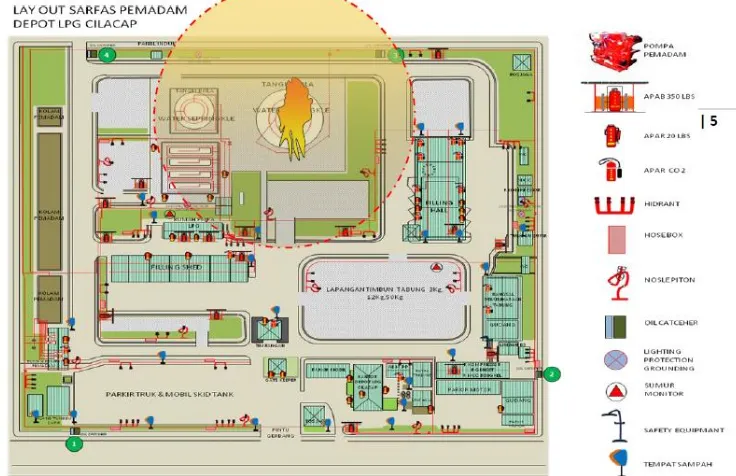
The consequences modelling of this case is using software called ARCHIE to determine the effect of the event. The result of the modelling later become the baseline to evaluate the existing firefighting equipment in Depot LPG Cilacap. The result of the assessment concluding that certain firefighting facility is not comply with the minimum requirement based on NFPA (National Fire Protection Agency). The recommendation of this paper is to evaluate the facility to overcome the event in the future based on a recent accident that happened. The affected area of the leakage can be seen in Figure 1.2.
Figure 1.2 Terminal Layout Cilacap LPG Terminal (Pertmina HSSE Jawa Tengah, 2012)
3
so called quantitative risk assessment. But as the stage in risk assessment cannot suddenly to modelling the outcome without doing another assessment to support the consequences modelling that can become baseline for pre fire planning or fire risk assessment.
To do the complete fire risk assessment several methods also need to do as a complete schematic stage to perform a risk assessment. First is to determine the hazard that may occur using HAZOP (Hazard and Operability) method. This will reveal potential hazard in every component that involving in Terminal’s operation.
The next stage performs the frequencies analysis and the system failure analysis. As each components potential hazard that may occur already examine in HAZOP assessment, the system failure, and its consequences also need to be determined. At this stage, the idea of using FTA (Fault Tree Analysis) and ETA (Event Tree Analysis) will be used. Event trees and fault trees are logic diagrams used to represent, respectively, the effects of an event and the contributory causes of an event (Mannan, 2005).
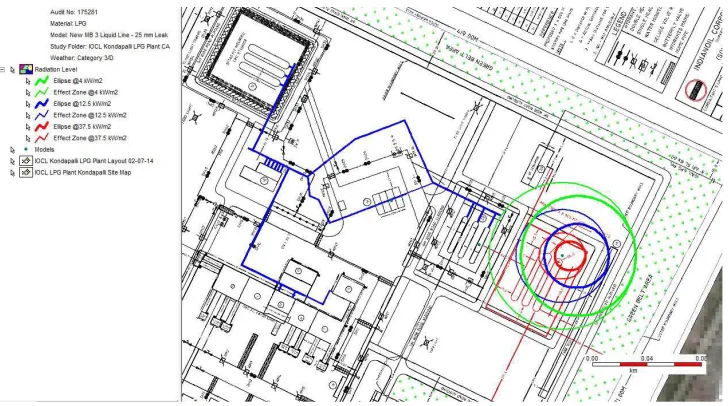
The next step is to modelling the possible outcome from FTA and ETA analysis using Consequences Modelling. Consequences modelling is a method to predict or calculate the physical damage and losses or how big the area is threatened due to a certain accident involving hazardous or toxic substances in oil & gas, processing, distribution, and transmission industry. The visual outcome can be seen in Figure 1.3. In one case the end point of the consequences can be predicted as well as the amount of heat radiation or flux during the event.
On this thesis, the software that chosen is Process Hazard Analysis Software Tools. Process Hazard Analysis Software Tools is one of most comprehensive hazard analysis software for all stages including process industry, design, and operation will very comply with the problem above, since Process Hazard Analysis Software Tools is can analyze the present potential hazard that may occur accurately and also provide clear illustration of the outcomes that may result from the modelling process. Process Hazard Analysis Software Tools is also in compliance with the safety regulations that are strictly monitored in oil and gas industry. Regarding the background above doing the consequences modelling using Process Hazard Analysis Software Tools can be used as a platform for Terminal LPG Semarang to create such as detailed and specific assessment (DNV, 2014).
existing facility in Terminal LPG Semarang are capable to overcome fire incident that may occur.
Figure 1.3 Consequences Modelling Result (UltraTech Environmental Consultancy and Laboratory, 2015)
All the methods that being implemented hopefully become a recommendation for Terminal LPG Semarang as an platform to perform further risk assessment and also evaluation for their facility so that in the future there will be major safety improvement in Terminal LPG Semarang.
1.2. Statement of the Problem
The process of thesis is to determine several problem that have to be answered during the research, in this thesis the problem are:
1. How to determine the Hazard and Operability Scenario on Terminal LPG Semarang using BS IEC 61882-2001 HAZOP standard?
2. How to analyze the system failure and event frequencies using FTA (Fault Tree Analysis) and ETA (Event Tree Analysis) methods?
3. How did the consequences modelling outcome using Process Hazard Analysis Software Tools?
4. How to formulate the risk outcome using Company Risk Matrix?
5. What needs to be evaluate in firefighting equipment based on consequences modelling outcome?
5
1.3. Problem Limitations
The problem limitation of this thesis are:
1. This thesis scope is at entire section of the Terminal’s facility including receiving, storage, and distribution facility but not consider the potential loss outside Terminal surrounding.
2. Consequences analysis of this research only based on iginited hazard. 3. The quantity of LPG in storage are considered at its maximum amount
(2500 MT).
4. The system work are considerd in its maximum capacity.
5. The representation of severity only assess the indiviual losses and not assess through operational losses point of view.
.
1.4. Research Objectives
1. Identify the potential hazard using Hazard and Operability Assesment. 2. After the potential hazard identified, the process is necessary to describe
systems failure frequencies using Fault Tree Analysis and Event Tree Analysis.
3. The probable consequences based on event which has been determined have to be calculated using Process Hazard Analysis Software Tools. 4. To examine whether the possible risk are acceptable or not using
company risk profile formulation.
5. To assess the pre fire planning as further mitigation
6. To conclude the Pre Fire Planning to overcome the possible action to take in certain occurence.
1.5. Research Benefits
As the process of assessment in this thesis are involving various and sequential Quantitative Risk Assessment methods each method is giving Terminal LPG Semarang greater improvement in their safety aspect. The hazard identification process in this thesis is giving Terminal LPG Semarang major depiction in their LPG handling system which aspects and components may lead into posible hazard in operational prpocess.
The Frequency Analysis in this thesis are giving Terminal LPG Semarang detailed calculation of the failure frequency and probability of their commponents in LPG handling systems. The quantitive result on this assessment stage are giving Terminal LPG Semarang the chance to determine its risk based ranking by the quantitative result.
the consequences will impact the societal aspect and the effect of certain event that can lead into another or escalated effect that may occur.
7
CHAPTER 2
LITERATURE STUDY
2.1. Recent Conditions
Terminal LPG Semarang as one of vital facility in LPG supply chain especially in Central Java region is one of gas facility that required to have absolute and strict regulation in safety standard including a planning of action to be taken when an accident occurred. Regarding of those requirement Terminal LPG Semarang is prosecuted to have a detailed procedure such as Fire Risk Assessment. The Fire Risk Assessment later will be a platform to examine pre fire planning. Pre fire planning is an method to plan such as action to overcome specific accident that may occur due to specific condition when the event of accident occur, in this case the pre fire planning is due to fire event.
The things that considered in pre fire planning are mostly the action that have to be taken when the fire event occur. Other things that consist in pre fire plan is the analysis of firefighting equipment such as sprinkle, fire hose, etc. to calculate the need of the firefighting equipment the calculation are based on the NFPA (National Fire Protection Agency) standard.
The effect of unavailability of the pre fire plan can be catastrophic. The escalation of the effect is can be increasing due to lack of action. The action has to be correct information and in details. Also the good action are has to be synchronize with good firefighting equipment planning.
The platform to plan and analysis whether the firefighting equipment or firefighting action is taken from the calculation and modelling how big the accident may occur based on specific condition that affect how catastrophic the event will. This can be done by certain method using consequences modelling with the correct and specific approach.
2.2. Previous Research
2.2.1. Hazard Potency Analysis Of LPG Loading Process In Terminal LPG Semarang
level is in medium or higher level. All LPG loading system should be analyzed to guarantee that the system would not cause small or big accident (Putra, 2016).
All LPG loading system should be analyzed to guarantee that the system would not cause small or big accident. An LPG loading system is a system that load propane and butane from the carrier vessel to the tank in the LPG plant. The system that have been analyzed then must be categorized based on it risk level, a low or moderate risk level shall not be mitigated while a medium or higher risk level shall be mitigated, the risk level itself was based on the risk matrix, this risk matrix had it definition to determine the probability and severity level, when the severity and probability number was combined, a risk level could be determined, which means risk level is a combination of severity and probability of a system or sub-system. The mitigation process shall reduce the risk xii level of the LPG loading process.
This research resulted in a decission that all the hazard are in allowed level so thet significant mitigatioin plant are not necessarily conducted.
2.2.2. Pre Fire Planning Assessment Of Depot LPG Cilacap.
On Thursday at 22 March 2012 at 10.00 PM on Cilacap LPG Terminal storage tank F which contains mixed LPG which ongoing LPG supply operations into corresponding tank from RU IV T-105 tank. Suddenly the fire spark is occur on the roof side of the tank, and the tank is also suffer a leakage on pressure release valve causing a fire on relief valve. The fire was first saw by one of the employee and immediately reported into tank security officer.
The consequences modelling of this case are using software called ARCHIE to determine the effect of the event. The result of the modelling later become the baseline to evaluate the existing firefighting equipment in Depot LPG Cilacap. The result of the assessment concluding that certain firefighting facility are not comply with the minimum requirement based on NFPA (National Fire Protection Agency). The recommendation of this paper are to evaluate the facility to overcome the event in the future based on recent accident that happened (Pertmina HSSE Jawa Tengah, 2012).
2.3. Theories
2.3.1. Liquefied Petroleum Gas (LPG)
Liquefied Petroleum Gas (LPG) or in Indonesia so called ELPIJI is a major fuel to support Indonesia’s household needs as cooking fuel. LPG contains 2 (two) main components of Hydrocarbons gases which are Propane (C3H8) and Butane
(C4H10). In Indonesia LPG for cooking purpose is mixture LPG with 50:50 ratio
9
been determine by Indonesia’s Ministry of Natural Resources (ESDM) can be seen in Table 2.1.
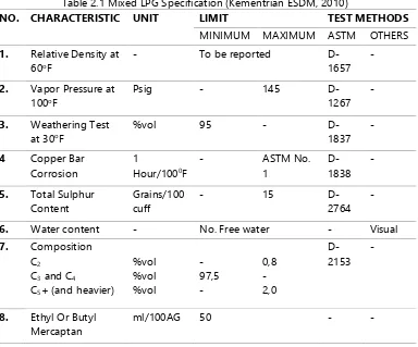
Table 2.1 Mixed LPG Specification (Kementrian ESDM, 2010)
NO. CHARACTERISTIC UNIT LIMIT TEST METHODS
MINIMUM MAXIMUM ASTM OTHERS
1. Relative Density at
60oF
- To be reported
D-1657 -
2. Vapor Pressure at
100oF
Psig - 145
D-1267 -
3. Weathering Test
at 30oF
%vol 95 -
D-1837 -
4 Copper Bar
Corrosion
1
Hour/1000F
- ASTM No.
1
D-1838
-
5. Total Sulphur
Content
Grains/100 cuff
- 15
D-2764 -
6. Water content - No. Free water - Visual
7. Composition
C2
C3 and C4
C5+ (and heavier)
%vol %vol %vol - 97,5 - 0,8 - 2,0 D-2153 -
8. Ethyl Or Butyl
Mercaptan
ml/100AG 50 - -
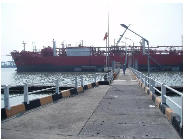
LPG in Indonesia mainly supplied by importing from another country and carried into floating storage in Teluk Semangka for Western Indonesia region and Kalbut for Eastern Indonesia region, then transferred into main receiving terminal accross Indonesia using Gas Carrier Ship as seen in Figure 2.1. From inland main terminal then carried by skid tank or truck with gas tank into bottling station or known as SPBE (Stasiun Pengisian Bahan Bakar Elpiji) accross the country before its distributed in botlled gas in various capacity such as 3 kg, 12 kg, and 50 kg.
Figure 2.1 Gas Carrier Ship Unloading Process
2.3.2. Hazard And Operability (HAZOP) Assessment
HAZOP (Hazard and Operability) is one of technique to analyze the potential hazard in specific system with the intention of knowing the cause from the guidewords that lead the analysis into what kind of consequences that may occur. This technique is a development from critical examination. It is a team exercise, which involves examining the design intent in the light of guidewords. The technique has itself been subject to numerous variations (Mannan, 2005).
The basic concept of the HAZOP study is to take a full description of the process and to question every part of it to discover what deviations from the intention of the design can occur and what the causes and consequences of these deviations might be. This is done systematically by applying suitable guidewords. Thus important features of the study are:
1. design intent 2. deviations
3. causes of deviations 4. consequences 5. hazards
6. Operating difficulties. (Mannan, 2005)
11
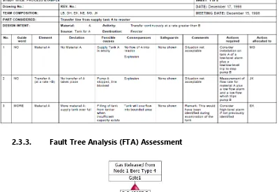
Table 2.2 Example of HAZOP Assessment (British Standard, 2001)
2.3.3. Fault Tree Analysis (FTA) Assessment
Figure 2.2 FTA Applications
2.3.4. Event Tree Analysis (ETA) Assessment
Event Tree Analysis is a method to predict the posible outcomes by showing it into graphs that show the probability of various scenarios and the consequences. The results of the Event Tree Analysis are accident sequences; that is, sets of failures or errors that lead to an accident. These results describe the possible accident outcomes in terms of the sequence of events (successes or failures of safety functions) that follow an initiating event (American Institute of Chemical Engineers, 1992).
As seen in Figure 2.3 show the typical LPG handing Event Tree Analysis result. The results of an Event Tree Analysis are the event tree models and the safety system successes or failures that lead to each defined outcome. Accident sequences depicted in an event tree represent logical and combinations of events; thus, these sequences can be put into the form of a fault tree model for further qualitative analysis (American Institute of Chemical Engineers, 1992).
Figure 2.3 Typical ETA for LPG Handling (Selvan, 2015)
2.3.5. Consequences Modelling Using Process Hazard Analysis Software Tools
Consequences modelling is one of the method to numerical and computational based modelling to predict what an accident can affect and what its physical outcome to the surrounding, and also show what its potential impact to people, assets or safety function.
13
Software) to do an approach is have their own boundaries/limits to calculation. For example for certain software which concerning about thermal and radiation approach are cannot to be used in smoke or toxicity approach. This limitation make the approach to overcome an event are have to be specifically determined and chosen to do such an analysis.
Process Hazard Analysis Software Tools is one of most comprehensive hazard analysis software for all stages including process industry, design, and operation will be very comply with the problem above, since Process Hazard Analysis Software Tools is can analyze the present potential hazard that may occur accurately and also provide clear illustration of the outcomes that may results from the modelling process. Process Hazard Analysis Software Tools is also in compliance with the safety regulations that is strictly monitored in oil and gas industry. The result is as shown in Figure 2.4 the modelling gives clear visual outcome that show the affected areas and the physical outcome such as heat flux.
Figure 2.4 Process Hazard Analysis Software Tools Modelling Result (DNV GL, 2015)
2.3.6. Consequences Evaluation: Fire, Release, Explosion, and Dispersion
2.3. The hazardous event that may appear also differ based on what kind of material and what kind of process involved.
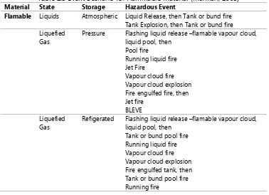
Table 2.3 Event Scenario for Flammable Material (Mannan, 2005)
Material State Storage Hazardous Event
Flamable Liquids Atmospheric Liquid Release, then Tank or bund fire
Tank Explosion, then Tank or bund fire Liquefied
Gas
Pressure Flashing liquid release –flamable vapour cloud, liquid pool, then
Pool fire
Running liquid fire Jet Fire
Vapour cloud fire Vapour cloud explosion Fire engulfed fire, then Jet fire
BLEVE Liquefied
Gas
Refigerated Flashing liquid release –flamable vapour cloud, liquid pool, then
Tank or bund pool fire Running liquid fire Vapour cloud fire Vapour cloud explosion Fire engulfed tank, then Tank or bund pool fire Running fire
2.3.6.1. Jet Fire
Basically Jet Fire is an event when certain material or gases release followed by ignition of the material. This caused spray fire which is turbulent diffusion flame resulting from the combustion of a fuel continuously released with some significant momentum in a particular direction or directions as seen in Figure 2.5. Jet fires can arise from releases of gaseous, flashing liquid (two phase) and pure liquid inventories (Cowley, 1992).
There are a lot of aspect that that make jet fire is become harmful such as: 1. Flame extent and geometry.
2. Ignitability, stability, and lift off. 3. Radiation to surrounding. 4. Directional stability.
5. Properties of combustion products (eg. Smoke, gases, liquids) 6. Heat fluxes.
7. Turbulence level and aerodynaics forces into fire.
15
Figure 2.5 Jet Fire (Kontrol, 2013)
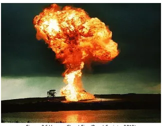
2.3.6.2. Vapour Cloud Fire
Figure 2.6 Vapour Cloud Fire (Royal Society, 2012)
Cloud Fires are transient event resulting from the ignition of a cloud of gas vapour and not subject to significant flame acceleration via the effect of confinment or turbulence (Cowley, 1992).
As can be seen in Figure 2.6 the example of cloud fire which an massive fire
that create such as “cloud-like” form.
2.3.6.3. Boiling Liquid Expanding Vapor Explosion (BLEVE)
BLEVE is simply explosively expanding vapor or two-phase fluid. A BLEVE results from a “hot rupture” of a vessel typically containing hydrocarbons such as LPG3, stored and maintained as a liquid under pressure, due to an impinging or
engulfing fire. A flammable material will be ignited immediately upon rupture by the impinging/engulfing fire and will burn as a fireball (International Associations of Oil and Gas Producers (OGP), 2010).
2.4. Standards
2.4.1. British Standard IEC 61882:2001 Hazard And Operabilities (HAZOP) Studies Applications Guide
As on methods on this assessment is to determine the potential hazard using Hazard and Operability (HAZOP) study one of the concern is determining the sguidance so tht during the process of hazard identification is going
objective.
British Standard as one of major standarization organization has provide a guideline to do HAZOP assesment. This is providing the method to be
standarize as one complete schematic stage that must be follow with the object of:
Identifying potential hazards in the system. The hazards involved may include both those essentially relevant only to the immediate area of the system and those with a much wider sphere of influence, e.g. some environmental hazards;
Identifying potential operability problems with the system and in particular identifying causes of operational disturbances and production deviations likely to lead to nonconforming products (British Standard, 2001).
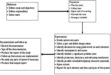
17
Definition
Define scope and objectives
Define responsibility
Select team
Preparation
Plan the study
Collect data
Agree style of recording
Estimate the time
Arrange a schedule
Examination
Divide system into parts
Select a part and define design intent
Identify deviation bu using guide words on each elements
Identify consequences and causes
Identify whether a significant problem exist
Identify protection, detection, and indicating mechanism
Identify possible remedial/mitigating measures (optional)
Agree actions
Report for each element and then each part of the system
Documentation and follow up
Record the examination
Sign off the documentation
Produce the report of the study
Follow up that actions are implemented
Re-study any parts of system if necessary
Produce final output report
Figure 2.7 British Standard for HAZOP Studies (British Standard, 2001)
2.4.2. DNV Failure Frequency Guidance
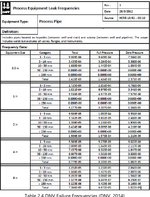
DNV as one of safety Assessor is providing data of failure or leak event from various source of process industry; DNV’s data is derived from the Hydrocarbon Release Database (HCRD) which has been compiled by the UK Health and Safety Executive (HSE) over a 20 year period The database contains details of over 4000 leak events at oil and gas installations in the UK Continental Shelf. It identifies 78 different types and size categories of process equipment, and records the quantity of the release and the release holes size (DNV, 2014). This data then proceed and analyze so that become an frequency analysis as shown in Table 2.4.and being used for various risk assessment in process industry.
Table 2.4 DNV Failure Frequencies (DNV, 2014)
2.4.3. International Association of Oil & Gas Producers (OGP) Storage Incident Frequencies
From various hydrocarbon containtment system around the world which
becomes OGP’s research object, OGP conduct datasheet about the failure or
incident frequencies per years that can be use as an baseline for determining our failure frequencies of hydrocarbons containtment systems. The datasheet presents frequencies of releases from the following types of storage:
19
5. Non-process Hydrocarbon Storage Offshore
6. Underground storage (International Association of Oil and Gas Producers (OGP) , 2010).
The complete table of pressurised storage cann be seen on Table 2.5.
Table 2.5 Pressurised Storage Failure Frequancies (International Association of Oil and Gas Producers (OGP) , 2010)
Hole Diameter Leak Frequency (per vessel year)
Range (mm) Nominal (mm) Storage Vessel Small Containers
1-3 2 2,3 x 10 -5 4,4 x 10 -7
3-10 5 1,2 x 10 -5 4,6 x 10 -7
10-50 25 7,1 x 10 -6
50-150 100 4,3 x 10 -6
>150 Catastrophic 4,7 x 10 -7 1,0 x 10 -7
Total 4,7 x 10 -5 1,0 x 10 -6
2.4.4. International Association of Oil & Gas Producers (OGP) Ignition Probability
In the process of gas leakage or release there are probability the released gas to be ignited so that its no longer release or dispersion, its become fire. OGP has conduct a research that identified the connection between released gases and its probability to be ignited. Development of the research deliver datasheets that can be use to predict the probability of ignited gas release. The complete datasheet table for specific scenarios in this thesis can be seen on Table 2.6.
Table 2.6 OGP Ignition Probability (Oil and Gas Producers, 2013)
Large Plant Gas LPG
Release of flamable gases, vapour or liquids significantly above their normal (NAP) boiling point from large onshore outdors plants.
Release Rate (kg/s) Ignition Probability
0,1 0,0010
0,2 0,0014
0,5 0,0019
1 0,0025
2 0,0050
5 0,0125
10 0,0250
20 0,0500
50 0,1250
100 0,2500
200 0,5000
500 0,6500
1000 0,6500
2.4.5. NFPA 15 Standard for Water Spray Fixed Systems for Fire Protection
Table 2.7 Requirement for Flow Rate (NFPA, 2007)
Pipe Size Flow
In. mm gpm L/min
4 100 300 1.476
6 150 880 3.331
8 200 1.560 5.905
10 250 2.440 9.235
12 300 3.520 13.323
As the evaluation of fire protection system in Terminal LPG Semarang there should be an standar as an standard and guideline. This will determine whether the facility in Terminal LPG Semarang are comply with certain regulation and can overcome certain fire incident. For example as shown in Table 2.7. there are minimum flow rate for water spray supply.
21
CHAPTER 3
METHODOLOGY
3.1. Methodology Flowchart
Sta rt
Statement of the problem
Literature Study
Data Collection 1. Terminal Layout a nd P&ID 2. Terminal Facility 3. Terminal Ambient Paramaters 4. Release Frequecies 5. LPG Properties Hazard and
Operability (HAZOP) Analysis
Fault Tree Analysis (FTA)
Event Tree Analysis (ETA)
1. Recent Conditions 2. Theories 4. Sta ndards -BS IEC 61882:2001 -DNV Leak Frequencies -NFPA 15
Consequences Modelling Using Process Hazard Analysis Software Tools
1. Event Occurance 2. Ambient Paramater
Pre Fire Planning
Does System Comply The Requirement ?
Recommendation Yes No Conclus sion Evaluation End Risk Mapping
Compa ny Risk Matrix
3.2. Research Methodology
Research methododlogy is the proposed solution methods to solve the problem at one specific research. On this thesis the main framework for solving the problem are consist of 4 (four) stage, which are: hazard identification, frequency analysis using fault tree and event tree analysis, consequences modelling, and pre fire planning evaluation. The complete stage of this thesis methodology will be explained further below.
1. Statement of the problem
First to identify the problem to determine what kind of formulation and methods to be taken. This is the initial stage to start the research. The amount of problem and the limitation are things to be considered during this stage, and in the middle of the research there are might be correction depend on the course of the research.
2. Literature Study
There are a lot of reference to do a research. On this stage all the reference during this thesis work will be reviewed. This including the basic theories that come from various literature source, recent condition, and standard including: BS IEC 61882:2001, DNV Leak Frequencies, NFPA 15. And also various previous resaerach on risk assessment that may useful to this thesis.
3. Collection of Data
One of the main stage of this research are to be modelling the consequences of accident that may occur and its effect. The modelling process is need various data to be considered an as close as actual condition in operation process. This data collection have very big influence further in analytical process so the validity of data are the things that need to be considered very carefully.
Kind of data that need to be collected in this research are such as: Terminal Layout and P&ID, Terminal facility, Terminal operation data, Terminal ambient parameters, Release frequencies, LPG Properties. 4. Hazard and Operability (HAZOP) Analysis
Potential cause of failure describes how a process failure could occur, in terms of something that can be controlled or corrected. The goal is to describe the direct relationship that exists between the cause and resulting process failure mode. The major steps to do HAZOP assessment are: 1. Preparing for the review, 2. Performing the review, and 3. Documenting the results. (American Institute of Chemical Engineers, 1992)
23
Based on previous HAZOP assessment the FTA determine the probability of failure event that may occur. There are four steps an analyst must take to perform a Fault Tree Analysis: 1. defining the problem, 2. constructing the fault tree, 3. analyzing the fault tree model qualitatively, and 4. documenting the results (American Institute of Chemical Engineers, 1992).
6. Event Tree Analysis
Event Tree Analysis evaluates the potential for an accident that is the result of a general type of equipment failure or process upset (known as an initiating event. The general procedure for Event Tree Analysis contains six steps: 1. identifying the initiating events of interest that can result in the type of accident of concern, 2. identifying the safety functions designed to mitigate the initiating event, 3. constructing the event tree, 4. describing the resulting accident sequence outcomes, 5. determining the accident sequence minimal cut sets, and 6. documenting the results. 7. Consequences Modelling
From the event which already predicted using ETA the actual consequences will be modelling using Process Hazard Analysis Software Tools. This will give clear visual representation how the consequences will affect, and the effect of the occurence.
8. Risk Representation
From the analysis the posible risk outcome will be determined for each scenarios. Every possible occurence will be represented into company based risk evaluation whether the outcomes are acceptable (low risk) or not. The desired result are the majority scenarios will be not in high risk level area. But if theres any medium or high risk outcome there will be mitigation efforts. The risk mapping in this thesis will be using company risk matrix where the company already determine by themself
which grouping certain risk by it’s severity and occurence likelihood.
9. Pre Fire Planning Evaluation
The modelling give result that can be a baseline to evaluate the terminal facility whether the consequences that may be occur can be overcome by terminal facility. This resulting as pre fire planning which this stage when pre fire planning will be made. The standard thet will be used is NFPA 15. If there’s found incompliance the process will prosecuted into evaluation of terminal facility.
10. Result and Discussion
This stage are summarize the analytical stage and evaluation stage, and also considering certain deviation that may occur.
25
CHAPTER 4
DATA REQUIREMENT
4.1. General Description
This thesis analyze potential fire risk and pre fire planning to overcome the fire occurrence that may occur based on the risk evaluation using quantitative risk assessment, with Terminal LPG Semarang as an object to assess. The scope of the assessment are in entire system on the terminal which handling the LPG including receiving (from tanker ship), storage, and distribution process.
4.2. Data Requirement
In the assessment process there are required several data to support the assessment process, the required data on this thesis are:
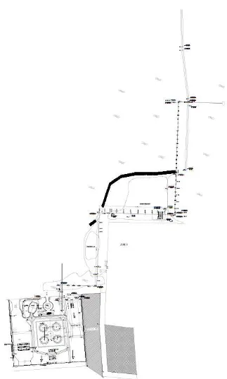
4.2.1. Terminal Plant Layout
The terminal layout are required to give the depiction of the area to be assess and further the layout also needed to plot the consequences evaluation. The brief layout of Terminal LPG Semarang can be seen on Figure 4.1. The lyout of Terminal LPG Semarang shows the coverage area of entire Terminal. The Jetty which exceed 1.200 m consist of the Jetty area of Marine Loading arm, Trestle area, and the pipeline exceed into partial part of shoreline. The Terminal area consist of Tank Farm, office, filling shed, pumphouse and skid tank parking area. The more detailed layout can be seen on Appendix 1.
4.2.2. Systems Piping and Instrumental (P&ID) Diagrams
To find certain possible hazard on the systems the analysis is involving to analyze how the systems works and during operational what are the possible failure that can lead into hazard. To do that it required the complete schematic P&ID of the systems and its components so it can be analyze. Considering in this thesis will be assess entire terminal system from receiving (from tanker ship), storage, and distribution the complete the following P&ID are:
1. LPG Ship Loading and Unloading P&ID
2. LPG Loading Storage Tank P&ID (consist 2 sheets of documents)
3. LPG Loading Pumps and Filling Points P&ID (consist 3 sheets of documents)
4. Fire Water Distribution System P&ID.
27
4.2.3. Company Risk Matrix
The risk mapping process require the standard to determine the level of risk. To fulfill the process this thesis will be using company risk matrix as standard (Terminal LPG Semarang, 2013). The risk matrix consist of two axis which determine the likelihood and the severity of certain risk. The ranking of each aspect then otted into matrix then the resul will be determine as the risk level. The description of likelihood and severity can be seen on Table 4.2. and 4.3. The risk matrix can be seen on Figure 4.4.
Table 4.2 Company Risk Likelihood Descriptions (Terminal LPG Semarang, 2013)
Likelihood
Level Criteria Description
Qualitative Quantitative
1 Rare Considered but not only in
extreme condition.
Less than 1 time in 10 years.
2 Unlikely Not happen yet but can be
occur sometimes
1 times in 10 years.
3 Possible Supposed to be occur here / in
other places.
1 time in 5 years until 1 time a year.
4 Likely Easily occur, might occur in a
more likely way.
More than 1 time a year until 1 time a month.
5 Almost
certain
Often occur and appear in a often occurence.
More than 1 times a month.
Table 4.3 Company Risk Severity Descriptions (Terminal LPG Semarang, 2013) Consequences / Severity
Level Description Severity Workdays
1 Not
significant
Occurence does not caused loss or injury.
Not causing loss of workdays
2 Minimal Causing minor injury and no direct
effect into business activity.
Still can work on the same day / shift.
3 Moderate Major injury and hospitalized but not
causing permanent disability, and moderate financial loss.
Loss of workdays under 3 days.
4 Major Major injury and permanent disability
and major financial loss and seriously damage business activity.
Loss of workdays more than 3 days.
5 Catastrophic Serious causality (die) and stopping
business activity forever
RISK LEVEL L IK E L IH O O D
5 5 10 15 20 25
4 4 8 12 16 20
3 3 6 9 12 15
2 2 4 6 8 10
1 1 2 3 4 5
SCALE
1 2 3 4 5
SEVERITY CONSEQUENCES
Figure 4.3 Company Risk Matrix
Definitions
Low Risk Medium Risk High Risk Extreme
4.2.4. Terminal Fire Fighting Arrangement and Components
The arrangement are required to assess whether the firefighting facility can overcome the possible outcome. The terminal Fire Fighting can be seen on Figure 4.3. The terminal Fire Fighting facility also can be seen on Table 4.1, and the complete equipment list can be seen on Appendix 3.
Table 4.1 Fire Fighting Equipment (Terminal LPG Semarang, 2013)
Fire Fighting Equipment
Quantity Amount Brand Type Engine Mover
Fixed Fire Pump cap @3000 GPM
Unit(s) 4 Amarillo Vertical Clarke Diesel
Amarillo Vertical Clarke Diesel
Amarillo Vertical Clarke Diesel
Amarillo Vertical Clarke Diesel
Jockey Pump Cap. 13.51 GPM
Unit(s) 2 Grunfos Vertical - Electric
Mufitec Vertical - Electric
Fixed Fire Pump Jetty Area Cap 1000 GPM
29
As a primary system to overcome fire evnent in the Terminal are using fresh water as an estinguisher the firefighting system in Terminal LPG Semarang are mainly consist of fixed water spray or sprinkle and fire hose. All the main estinguisher are provided with water from water pond using main fire pump which use diesel as a prime mover. The water pond get its water from external resource so that the design intent of the fire fighting system are closed loop so that no external resources (such as sea water coming from the sea which surround the Terminal) are intentionally come in handy when in condition of the water pond is out of water.
31
CHAPTER 5
TERMINAL SYSTEM DESCRIPTION
5.1. General Description
Terminal LPG Semarang consist 3 (three) main subsystem on its facility. The first are receiving subsystem that conduct receiving operation of bulk LPG from Gas Carrier Ship the second subsystem is storage of LPG in storage tank. The last subsystems are distribution system that responsible in transferring the LPG from storage tank into filling station related with the transfer process into Skid Tank (Truck equipped with tank) for transportation into the destination.
5.2. Receiving System
During receiving operations of bulk LPG from ship, the LPG are transfered using pump onboard ship. The preliminary step of the transfer process are including the connection of Terminal’s Marine Loading Arm (MLA) into ship’s manifold.
The major components to be considered in Receiving subsyetem are Marine Loading Arm (MLA) as seen on Figure 5.1 which connect the shore with ship’s manifold. Materring station as shore measurement components to calculate the amount and flow rate of the LPG. And Mercaptan injection station as component with the purpose of odorizing the LPG. Another components to be considered are main pipeline, various valve such as Shutdown Valve (SDV). Control Valve (CV), erc. Also various measuring components such as: Temperature Indicator (TI), Pressure Indicator (PI), etc.
This system are using 10” pipeline as a main pipe, the complete components specification of this system are:
Marine Loading Arm
Producer: Woodfield Systems Limited Equipment Type: Hydraulic Lever Model Number: A2/08/1200/600/008 Manufacturing year: 2008
Flow/Pressure: 4 LMP/13,6 BarG Ship Unloading Meterring Package
Max. Flow Rate : 300 MT/Hr Operational Press : 7-14 BarG Operational Temp. : 5-30oC
Vapour Return Meterring Package Max. Flow Rate : 8 MT/Hr Operational Press : 7-14 BarG Operational Temp. : 5-30oC
The process of loading LPG into shore storage tank beside the liquid LPG loading are also involve with unloading the LPG vapour back into Gas Carrier Ship. The process make the receiving process also invlove two different flow of fluids: the liquid LPG flow into storage tank, and Vapour LPG from storage tank into Gas Carrier Ship which using 4” pipelines. The complete system P7ID can be seen on Appendix 2.
33
5.3. Storage Tank System
The next system is storage tank system, storage tank are the end point of transferring LPG from Gas Carrier after injected by Mercaptan. The Storage Tank type are Spherical type storage as seen on Figure 5.3. As main system of handling that involve a lot amont of LPG the storage tank are equipped with various safeguard and measurement and instrumentation of LPG Cpndition such as: Atomatic Tank Gauging (ATG), Pressure Safety Valve (PSV), Pressure Indicator (PI), Temperature Indicator (TI), etc.
Figure 5.3 Spherical Storage Tank
The operational activity on storage tank subsystem are consists of receiving activity, intertank activity, and distribution activity. The activity listed above are supported by various dimension of pipeline. The pipeline for receiving and
intertank activity are using 10” pipelines, the distribution activity are using 12”
pipelines. Meanwhile the vapour return line are using 4” pipelines. The techinical specification for Storage Tank are:
Size : 21216 mm
Capacity : 2500 MT
Operation Press. : 7-14 BarG Operating Temp : 5-30oC
Manufacturer : Shi-Asia Company LTD Design Pressure : 17,2 BarG at 700C
Test Pressure : 21,93 kg/cm2 (Top of vessel)
Min. Metal Design
Temp. : Minus 100C
5.4. Distribution Subsystem
Distribution system are responsible for distribute the LPG into filling point as well as do intertank operation. The distribution system are consist of 4 (four) LPG Pumps, and that supply activity in filling point into Skid Tank using Quick Coupling Connection. The operation of 4 (Four) LPG pumps are redundant considering the operation cycle requested by distribution division so that the redundant system are designed the distribution are still can fulfill the need when something happend with one of the pump. Also in the system is consist of one unloading pump from skid tank in a case when overfilling is happend into Skid Tank. In normal distribution activity usually 2 (two) LPG pumps are used.
The distribution process from storage tanle into pumps suction head are
using 12” pipelines, and reduced into 6” pipelines so do with the pipelines in
filling point. Meanwhile the filling process into skid tank are using various size of pipelines depends on the intent of the operational.
The technical specification for distribution subsystem are: LPG Pumps
Type : Centrifugal Pump
Flow rate : 30 MT/hr max 50 MT/hr Max. Press. : 17,24 BarG
Rated Discharge
Press. : 205,65 psi ~ 13, 99 BarG
35
CHAPTER 6
HAZARD AND OPERABILITY (HAZOP) STUDY
Hazard and Operability (HAZOP) study giving the detailed assessment of the potential hazard which may occur. The basis of HAZOP is a “guide word
examination” which is a deliberate search for deviations from the design intent (British Standard, 2001). The basic concept of the HAZOP study is to take a full description of the process and to question every part of it to discover what deviations from the intention of the design can occur and what the causes and consequences of these deviations might be. Based on BS IEC 61882:2001 the process of HAZOP study are include in determining the nodes, deviations, safeguards, and another criteria to support the study.
6.1. Node Classification
The LPG handling facility consists of various system that divided into main division: Receiving (from Gas Carrier), Storage, and Distribution. The complete system of the Terminal as P&ID can be seen in Appendix 2. The main division still consist of several subsystem that support the Terminal Activity based on P&ID classification eventhough certain process need to be separeted due to different flow direction and different operational intent. The node classification is ease us to assess the HAZOP study since every subsystem are consist of various components and also different operational intent. The complete node classifications can be seen on Table 5.1. above.
The technical description of the node classification above are:
1.
Node 1This Node are concerned in liquid loading line from Gas Carrier into meterring station this system are divided based certain part in unloading system and Jetty Area. Considering the length of unloading line are 1.200 m that divides into in Trestle area and shore area, every line need to be separate since the system has its own hazard potency based on its location. The part considered in this node are MLA (Marine Loading Arm) Liquid loading line, and pipeline located on trestle and causeway. The specification of liquid loading line of MLA are mentioned below:
Max. Flow Rate : 300 MT/Hr Operational Press : 7-14 BarG Operational Temp. : 5-30oC
The concern of this node are the system of liquid loading LPG from Gas Carrier into meterring station and located in shore area. Since this node are exposed into labour and open space rather than enclosed area like node 1. The part considered in this node are meterring station that show how much amount of Liquid LPG that transferred from Gas Carrier.
3.
Node 3The loading process of liquid LPG are followed by the unloading process of LPS vapour from storage tank into Gas Carrier. The reason why this line need to be separate into different node are because the flow direction and the type of fluids involved are different than loading line. The process of vapour return are only involving vapour phase of LPG rather than liquid phase. The consideration of this node to be determined are because this line are located in shore are of the Terminal. The part considered in this node is vapour return meterring station.
4.
Node 4This node is considered as the vapour return line at trestle or causeway area the pipeline are located in same location as node 1 but with different fluuids and flow direction works eventhough with the same part consideration such as MLA (Marine Loading Arm).
5.
Node 5This node classified storage tank subsystem that consist 4 (four) storage tank which are V110, V120, V130, and V140. This node are assess the possible hazard on storage in all operation intent into all storage tank. The operational specification of this node are:
Size : 21216 mm
Amount of Storage : 4( four)
Capacity : 2500 MT
Operation Press. : 7-14 BarG Operating Temp : 5-30oC
6.
Node 6: Receiving OperationApart from storage tank itself, the storage tank system have the pipelines that have to assess separately since the system has different components and different safeguard implementation comparing with the storage tank itself. The operational specification of this node are:
Pipe Size : 10” Pipe, 4” Pipe (Vapour Return)
37
Operation Press. : 7-14 BarG Operating Temp : 5-30oC
7.
Node 6: Distribution OperationThis process has the same design intent with Node 3: Receiving above but with differetnt operational intent, this node conduct assess in distribution operation. The operational specification of this node are:
Pipe Size : 12” Pipe Flow Rate : 30 - 50 MT/Hr Operation Press. : 7-14 BarG Operating Temp : 5-30oC
8.
Node 6: Intertank OperationThis process has the design intent with Node 3: Receiving with Intertank Operation. The operational specification of this node are:
Pipe Size : 12” Pipe Flow Rate : 30 - 50 MT/Hr Operation Press. : 7-14 BarG Operating Temp : 5-30oC
9.
Node 7Node 4 is conduct assessment on LPG Pumps system. This pump provide the distribution into filling point. On this system consists of 4 (four) identical LPG Pumps with redundant operation. The technical specification of this node are:
Type : Centrifugal Pump
Flow rate : 30 MT/hr max 50 MT/hr Max. Press. : 17,24 BarG
Rated Discharge
Press. : 205,65 psi ~ 13, 99 BarG
10.
Node 8Table 6.1 Node Classification
No P&ID Drawing Code and Description
Node Classification Description
1 FTLS-30-DW-C006
LPG Ship
Loading/Unloading P&ID
Node 1 Liquid loading MLA
(Marine Loading Arm), Liquid loading line at trestle/jetty area
2 FTLS-30-DW-C006
LPG Ship
Loading/Unloading P&ID
Node 2 Liquid loading line at
shore area and meterring station
3 FTLS-30-DW-C006
LPG Ship
Loading/Unloading P&ID
Node 3 Vapour return line
located in shore area, and vapour return meterring station
4 FTLS-30-DW-C006
LPG Ship
Loading/Unloading P&ID
Node 4 Vapour return line
located in trestle and jetty, Vapur return MLA (Marine Loading Line)
5 FTLSMG-30-DW-C007
LPG Loading Storage Tank V110, V120, V130, V140 P&ID
Node 5 Storage Tank V110,
V120, V130, V140
6 FTLSMG-30-DW-C007
LPG Storage System Pipelines
Node 6: Receiving Operation
Storage System Pipelines Receiving Operation
Node 6: Distribution Operation
Storage System Pipelines Distribution Operation
Node 6: Intertank Operation
Storage System Pipelines Intertank Operation
7 FTLSMG-30-DW-C008
LPG Loading Pumps
Node 7 LPG loading pumps in
Distribution Operation
8 FTLSMG-30-DW-C008
Filling Point P&ID
Node 8 LPG Filling/Distribution