Howard Gould
Database Design and
Implementation
A practical introduction using Oracle SQL
Howard Gould
Database Design and Implementation
3
Database Design and Implementation: A practical introduction using Oracle SQL
1
stedition
© 2015 Howard Gould & bookboon.com
ISBN 978-87-403-1046-7
A practical introduction using Oracle SQL Contents
Contents
Acknowledgements 8
Foreword 9
1 Introduction to database development 10
1.1 Conceptual data modelling 11
1.2 The Entity Relationship Diagram (ERD) 12
1.3 Entity types 12
1.4 Producing the ERD 14
1.5 Entity attributes 14
1.6 Entity selection and validation 15
1.7 Entity definitions 19
1.8 Validating the model 20
www.sylvania.com
We do not reinvent
the wheel we reinvent
light.
Fascinating lighting offers an infinite spectrum of possibilities: Innovative technologies and new markets provide both opportunities and challenges. An environment in which your expertise is in high demand. Enjoy the supportive working atmosphere within our global group and benefit from international career paths. Implement sustainable ideas in close cooperation with other specialists and contribute to influencing our future. Come and join us in reinventing light every day.
A practical introduction using Oracle SQL
5
Contents
2 Entity Relationships 21
2.1 Introduction 21
2.2 Relationships 21
2.3 Relationship cardinality 24
2.4 Relationship optionality 27
3 Complex relationships 31
3.1 Introduction 31
3.2 Associative relationships 32
3.3 Link entity identifier 34
3.4 Recursive relationships 37
3.5 Sub types 40
3.6 Exclusive relationships 42
3.7 Summary 42
4 Logical Database Design 44
4.1 Introduction 44
4.2 Relations 44
4.3 Keys 45
4.4 Identifying relations 46
Click on the ad to read more Click on the ad to read more
360°
thinking
.
© Deloitte & Touche LLP and affiliated entities.
A practical introduction using Oracle SQL Contents
4.5 Resolving many-to-many relationships 49
4.6 Resolving one-to-many relationships with optionality 51
4.7 Resolving one-to-one relationships 52
4.8 Recursive relationships 54
4.9 Exclusive relationships 55
4.10 Identification Dependency 55
4.11 Modelling problems 57
4.12 Summary 58
5 Normalisation 62
5.1 Introduction 62
5.2 Un-normalised form (UNF) 63
5.3 First Normal Form (1NF) 69
5.4 Second Normal Form (2NF) 72
5.5 Third Normal Form (3NF) 77
5.6 Denormalisation 80
5.7 Checking the model 80
5.8 Summary 80
6 Introduction to Oracle SQL 85
We will turn your CV into
an opportunity of a lifetime
Do you like cars? Would you like to be a part of a successful brand? We will appreciate and reward both your enthusiasm and talent. Send us your CV. You will be surprised where it can take you.
A practical introduction using Oracle SQL
7
Contents
7 Using Foreign Keys 104
8 Selecting data from a table 108
9 Selecting data from multiple tables 115
10 Subqueries and group functions 123
11 Creating pages & reports 129
12 Appendices 153
12.1 Appendix A. UML Modelling Notation 153
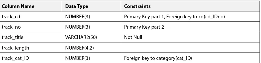
12.2 Appendix B. Music System Specification (ERD and Tables) 156
12.3 Appendix C. Order System Specification (ERD and Tables) 160
12.4 Appendix D. Normalisation Template 163
13 Bibliography 164
Click on the ad to read more Click on the ad to read more Click on the ad to read more Click on the ad to read more
AXA Global
Graduate Program
A practical introduction using Oracle SQL Acknowledgements
Acknowledgements
I should like to express my gratitude to colleagues at Leeds Beckett University (formerly known as Leeds Metropolitan University) for reviewing the manuscript and making helpful suggestions. Particular thanks go to Dr Mark Dixon for developing the QSEE CASE tool. The idea for this book evolved from teaching an introductory level databases module to undergraduate computing students for many years. The main material used by the module was a workbook developed and delivered by a number of staff at Leeds Beckett University, and this book is based on some of the ideas and content of the workbook; I would like to thank colleagues past and present for their contributions to the original student workbook, and apologise to those who I have been unable to formally acknowledge here.
Trademarks
Some of the product and company names used in this book have been used for the purpose of identification only and may be trademarks or registered trademarks of their respective manufacturers and sellers.
Oracle is a registered trademark of Oracle Corporation and/or its affiliates.
Microsoft is a registered trademark of Microsoft Corporation in the United States and/or other countries.
A practical introduction using Oracle SQL
9
Foreword
Foreword
This book has been written to provide a practical introduction to relational database design and database development for students studying computing-related courses and anyone else who needs to work with relational databases, either as users, designers or developers. Similarly, people who are commissioning a database may benefit from an understanding of this content.
This book is based on an approach that has been used successfully over a number of years to teach many undergraduate computing students, and is presented in a concise form that will make it easy for you to grasp the essential principles and techniques and apply these in any relational database environment.
An established data modelling methodology is explained which includes Entity Relationship models. These are presented using the long-established crow’s foot notation; however, as the Unified Modelling Language (UML) has become an industry standard, the Class Diagram notation is also introduced to show how it can also be used for ER modelling, though there are differences (Hay & Lynott, 2008).
The modelling diagrams used in this book have been drawn using the QSEE SuperLite v1.1.2 CASE tool which is available to download from http://www.leedsbeckett.ac.uk/qsee/.
The Oracle database management system and Oracle Application Express (APEX) development environment are used to introduce the industry standard Structured Query Language (SQL). An APEX user account can be obtained from apex.oracle.com for web access; alternatively, a copy of Oracle Database 11g Express Edition and Oracle APEX can be downloaded from Oracle.com for installation on your own system.
A practical introduction using Oracle SQL Introduction to database development
1 Introduction to database
development
On completion of this chapter you should be able to:
• be aware of the database development lifecycle • understand the purpose of data modelling • identify the key terms used in data modelling.
Databases are at the centre of most information systems in everyday use, therefore it is important that they are designed and built using appropriate methods to ensure that they meet users’ requirements whilst being robust and maintainable. A database system is usually regarded as the database which contains related tables of data maintained by a database management system (DBMS), along with applications that provide controlled access to the database.
In order to build an effective database system it is important to understand and apply the database development lifecycle, which includes the following phases:-
1. Strategy and planning 2. Requirements analysis 3. Design
4. Development
5. Deployment/implementation 6. Operations and maintenance.
1. Strategy and planning – typically the cycle starts with the strategy and planning phase to identify the need and scope of a new system.
2. Requirements analysis phase – a more detailed requirements analysis will be carried out which will include identifying what the users require of the system; this will involve conceptual analysis.
A practical introduction using Oracle SQL
11
Introduction to database development
4. Development phase – this involves creating the database structure using an appropriate Database Management System (DBMS) and usually includes the development of applications that provide a user interface consisting of forms and reports which will allow controlled access to the data held in the database. This book will show how the Oracle relational database management system and the Oracle Application Express (APEX) application developer tool can be used for this purpose.
5. Deployment/implementation – when the system has been developed it will be tested, it will then be deployed ready for use.
6. Operations and maintenance – following the system release for use it will be maintained until it reaches the end of its useful life, at this stage the development lifecycle may restart.
1.1
Conceptual data modelling
Why do you need to model?
In many environments modelling is used to ensure that a product will satisfy the user’s requirements before it is produced. For example, an architect may use a scale model of a building so the client can see what it will look like before it is built. This allows for any changes to be made to the design following feedback and before any expensive building work takes place. Similarly, a modelling approach is needed when designing a database system so that interested parties can check that the design will satisfy the requirements.
How do you model a database system?
In order to design an effective database system you need to be able to understand an organisation’s information needs and, in particular, identify the data needed to satisfy these needs. Entity Relationship modelling (Chen P. 1976) is an important top-down analysis technique which is used to show the structure of the data used by a system. Initially, a conceptual model is produced which is independent of any hardware or DBMS system; this is achieved by using an Entity Relationship Diagram (ERD) or alternatively a UML Class Diagram (CD). This modelling technique will be used to determine how this business data is structured and show the relationships between the different data entities. The model forms the basis for the design of the database system that will be built.
A practical introduction using Oracle SQL Introduction to database development
1.2
The Entity Relationship Diagram (ERD)
The Entity Relationship Diagram (ERD) shows “entities” and the “relationships” that link them. The entities represent the data items needed by the system and the relationships show how the entities are related to one another. An “entity” is formally called an “entity type” and can be defined as:
“A group of objects with the same properties which are identified by the enterprise as having an independent existence.” (Connolly & Begg 2015, p. 406)
There are a number of notations used for drawing ERDs; this book will show you how to use the commonly used Crow’s foot notation (Barker 1990). In addition, as the Unified Modelling Language (UML) (www.uml.org) is becoming more widely established, Appendix A shows how the UML Class Diagram can also be used for data modelling. Using the Crow’s foot notation, each entity type is modelled on the ERD as a round-cornered box with the entity name inside it e.g.
Entity type
You should always use UPPER case letters for entity names, and the name of the entity type should be written in the
singular, e.g. INVOICE not INVOICES.
Remember, the entity symbol is used to represent the entity type, not the number of occurrences; this information will be added to the ERD later.
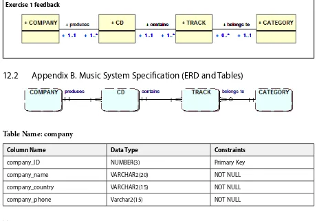
An example ERD for the Music System from Appendix B is shown below. This shows four entities – represented by round edge boxes – which are needed; production COMPANY, their music CDs which consist of TRACKs (i.e. songs). Each track is classified by a music CATEGORY (e.g. Pop, Rock). The lines and their symbols linking the entities are the relationships which provide further information about the entities.
Music System ERD
1.3
Entity types
A practical introduction using Oracle SQL
13
Introduction to database development
If modelling using the Unified Modelling Language (UML) then the term “instance” is used to refer to an entity occurrence.
You should consider the entity type as the definition or template of what data is to be held, and an occurrence as a single set of actual data e.g. entity type: STUDENT, occurrence “Mike Jones”.
Often many entities can be identified, although they are not always relevant to the needs of the system being considered, so care needs to be taken to ensure that only those that are needed are added to the ERD. The following are examples of typical entity types:
For a business system: CUSTOMER, ORDER, INVOICE. For a university system: STUDENT, LECTURER, COURSE.
Entities often fall into one of the following categories: Physical – CAR, BUILDING
Human – CUSTOMER, EMPLOYEE Place – FACTORY, SCHOOL
Group – DEPARTMENT, TEAM Document – INVOICE, PAYSLIP
Click on the ad to read more Click on the ad to read more Click on the ad to read more Click on the ad to read more Click on the ad to read more
as a
I joined MITAS because
Maersk.com/Mitas�e Graduate Programme for Engineers and Geoscientists
I wanted
real responsibili�
I joined MITAS because
A practical introduction using Oracle SQL Introduction to database development
1.4
Producing the ERD
When you have identified the entity types, these need to be added to the Entity Relationship Diagram (ERD). Although ERDs can be drawn by hand, it is good practice to use a Computer Aided Software Engineering (CASE) tool to ensure your models can be amended easily and presented in a professional form to others. There are many CASE tools available to support modelling.
The QSEE tool can be used to draw ERDs and UML Class Diagrams and is available to download from http://www.leedsbeckett.ac.uk/qsee/
CASE tools are more than just drawing tools; they are used to hold information about the data entities and their attributes (Meta data) and can be used to assist in the development stage of the database development lifecycle.
Exercise 1
Identify which of the following are likely to be entity types and which occurrences. If an occurrence, suggest a suitable entity type; if an entity type suggest a suitable occurrence:
PARIS, MODULE, AMIN KHAN, CUSTOMER, STUDENT, CITY
Exercise 1 feedback
ENTITY TYPE
ENTITY OCCURRENCE
CITY
Paris
MODULE
Introduction to Databases
CUSTOMER or STUDENT Amin Khan
1.5
Entity attributes
When you have identified your entity types you then need to identify their attributes. An attribute is defined as follows:
“A property of an entity or a relationship type” (Connolly & Begg 2015, p. 413).
Each entity will usually have a number of attributes. These are the individual items of data that you need to hold for each occurrence of an entity type. In some situations a relationship between a pair of entities may also yield attributes; this situation will be discussed later.
A practical introduction using Oracle SQL
15
Introduction to database development
An example entity occurrence of the entity type INVOICE would be as follows:
Invoice number 1102
Invoice date 12-Jan-2015
Invoice amount 1000
Customer code C101
Exercise 2
Which of the following are likely to be attributes and which are likely to be entity types? CUSTOMER, PRODUCT, ORDER, ORDER DATE, SIZE, QUANTITY, NAME.
Exercise 2 feedback
ENTITY TYPES: CUSTOMER, PRODUCT, ORDER. ATTRIBUTES: ORDER DATE, SIZE, QUANTITY, NAME.
1.6
Entity selection and validation
In order to produce the ERD you need to ensure you have identified the entities that are suitable for inclusion. The entities initially selected are usually referred to as “candidate entities” as not all may be suitable for inclusion. Entity names are normally nouns not verbs. The candidate entities are usually identified by referring to a written system description, a set of requirements, or perhaps the notes from a discussion with a person who has knowledge of the system under consideration. Read through the relevant documents and underline, highlight or draw a box around each noun (an item you can store information about). These nouns will form the candidate entity list.
To ensure that a candidate entity is valid for inclusion on the ERD it should satisfy the following three checks:
1. It should not be the name of the system being modelled
A practical introduction using Oracle SQL Introduction to database development
2. The object should be of importance to the system being studied
There are likely to be many objects in the system being studied but you have to decide whether the object is relevant. This usually means determining if the system users are likely to need to retrieve information about the object. For example, if you were designing a university student information system is a “litter bin” likely to satisfy the check? The answer would be no, but are there any circumstances in which it might? If the purpose of the system was to record all university assets, then you might need to record information about the litter bins. In that case you would need an entity type to represent this information, though the entity type would be called ASSET and bin would be an entity occurrence.
3. There should be data attributes that can be associated with the entity
There must be at least two attributes for an entity type. If you cannot identify any or only one attribute for the entity then you may need to consider whether, in fact, it is actually an attribute of another entity type.
Exercise 3
Identify the candidate entities for the following brief business system description. Then remove any of the candidates that do not satisfy the checks for an entity.
“Customers of the Yorkshire Supplies Co. order high and low value products. Most customers use a computer and so have an email address.”
M A ST E R I N M A N A G E M E N T
mim.admissions@ie.edu Follow us on IE MIM Experience
www.ie.edu/master-management
Av. Experience: 1 YEAR
Language: ENGLISH / SPANISH
Format: FULL-TIME
Intakes: SEPT / FEB
• STUDY IN THE CENTER OF MADRID AND TAKE ADVANTAGE OF THE UNIQUE OPPORTUNITIES THAT THE CAPITAL OF SPAIN OFFERS
• PROPEL YOUR EDUCATION BY EARNING A DOUBLE DEGREE THAT BEST SUITS YOUR
PROFESSIONAL GOALS
• STUDY A SEMESTER ABROAD AND BECOME A GLOBAL CITIZEN WITH THE BEYOND BORDERS EXPERIENCE
A practical introduction using Oracle SQL
17
Introduction to database development
Exercise 3 feedback
“Customers of the Yorkshire Supplies Co. place orders for high and low value products. Most customers use a
computer and so have an email address.”
An initial search for candidate entities may produce the following list:
CUSTOMER
If you now apply the three checks, YORKSHIRE SUPPLIES CO. would be eliminated as it fails the first check. There is only one, i.e. the system being modelled is the “Yorkshire Supplies Co.”
COMPUTER would be eliminated as it would not satisfy the second check, as it is unlikely that there would be a need to store details about a customer’s computer.
EMAIL ADDRESS would be eliminated too, as it fails the third check, however it is likely to be an attribute of CUSTOMER.
So you would be left with the following entity types which would be added to the ERD: CUSTOMER, ORDER, PRODUCT.
Once you have identified the entities needed for the system these can be added to the ERD. You should now try and identify the entity attributes. Following the entity checks some attributes may have come to light, either as a result of applying check two where the item may in fact be an attribute rather than an entity, or check three because you only have one attribute. To ensure you have identified all the required attributes you will need to analyse the system documentation which was used to identify the entities and discuss the system with its users to identify and extract all the items of data that are needed for each entity type. The entity and attribute information is usually recorded in a CASE tool repository to make it easier to reference during the system design and development phases. It is unlikely that you will identify all the attributes initially so you should always try and check with the users of the system to ensure that you have not missed any.
All entities require an entity identifier. This is an identifying attribute (or attributes) which is used to uniquelyidentify
an occurrence of an entity type.
For example:
A motor VEHICLE entity type can use the vehicle registration number as its unique identifier.
A practical introduction using Oracle SQL Introduction to database development
Q. Why can you not use ‘student name’ as the entity identifier for the STUDENT?
A. Because it is possible that you could have two or more students with the same name. In this case, the artificial identifier student id could be used as the unique identifier.
Exercise 4
What would be the identifying attribute in each of the following examples of entity types where some attributes have been identified?
CUSTOMER – Customer name, Address, Postcode, Customer code, Phone number. INVOICE –. Invoice Date, Invoice number, Invoice Amount, Customer code.
Remember, wherever possible you should use an existing attribute for the entity identifier and make sure that it will
always uniquely identify an occurrence of an entity type.
Exercise 4 feedback
For CUSTOMER the obvious choice would be Customer code.
Although Customer name might be considered, there may be more than one customer with the same name. Postcode may also be considered but this should be rejected as more than one customer may have the same postcode. Likewise, whilst no two customers should have the same phone number, this would not be a suitable choice as not all customers may have a phone number.
For INVOICE, the obvious choice would be Invoice number as this would be unique for each invoice. The other attributes would not be suitable as their values could be duplicated amongst all the invoices.
Exercise 5
For a university student information system list two entity types.
1. For each entity type list some of their attributes including an identifying attribute. 2. Produce a sample entity occurrence for each entity type.
Exercise 5 feedback
Entity type: STUDENT
Attributes: Student ID, Name, Address, Post Code, Date of Birth
Identifier: Student ID
Occurrence: S101, Paul Adams, 4 Long Row Leeds, LS6 3QS, 12-Jan-1960
Entity:
COURSE
Attributes: Course code, Course name, Start date
Identifier: Course code
A practical introduction using Oracle SQL
19
Introduction to database development
1.7
Entity definitions
It is important to ensure that anyone involved with designing the system is clear about the meaning of the entities being modelled. This is achieved by clearly documenting each entity type with a concise unambiguous definition. The list of definitions is referred to as the “data dictionary” or “data repository”
and is usually stored within a CASE tool as this provides a central reference point and allows for easy searching, amendment and reporting. Other information relating to the entities and their attributes may also be added to the data dictionary such as the number of likely entity occurrences and the data types and sizes of the attributes. This information may be needed in the design phase.
Here are examples of full definitions for some entity types.
Entity type Entity definition Entity Attributes
CUSTOMER A person or organisation who purchases products or services from the business.
Customer name, Address, Postcode, Customer code, Phone number.
INVOICE A request to a customer for payment for products or services supplied by the business.
Invoice Date, Invoice number, Invoice Amount, Customer code.
A practical introduction using Oracle SQL Introduction to database development
1.8
Validating the model
The model should be checked with the client or system users to ensure that all relevant entities have been identified, along with the required attributes. This process may need to be repeated a number of times until everyone is satisfied that all requirements have been met.
Remember it is easier and cheaper to change a model than it is to change a developed system.
Exercise 6
For the following business descriptions identify the candidate entities and eliminate any which are not entities, giving a reason for this.
For each remaining entity provide an entity definition and some suitable attributes including the identifying attribute.
1. A large business consists of a number of divisions. Each division has a number of departments. Each employee works for a department.
2. A car hire company’s customers make bookings to hire its cars. When a booking is made it is for a specific model of car and includes the collection and return dates. At the time of the booking the company may assign a particular car, however at the time of collection a different car may be provided. The company needs to keep records of which car each customer actually hired.
Activity 6 feedback
The identifying attributes are shown in bold. The # symbol is used to represent a number e.g. Employee number.
1. BUSINESS is eliminated as there is only one occurrence; you are modelling the business.
DIVISION
Attributes: Division Name, location, …
Description: A major functional area of the business.
DEPARTMENT Attributes: Department Name, office location, …
Description: A functional section within a division of the business.
EMPLOYEE
Attributes: Employee#, name, office, grade, ….
Description: A member of staff who works for one of the departments within the business.
2. CAR HIRE COMPANY is eliminated as you are only modelling the one.
CUSTOMER Attributes: Customer#, name, address, Tel no. …
Description: A person registered to hire cars from the company.
A practical introduction using Oracle SQL
21
Entity Relationships
2 Entity Relationships
On completion of this chapter you should be able to:
• understand what is meant by an entity relationship • identify and model entity relationships.
2.1 Introduction
In the previous chapter you started to use analysis techniques to try and identify a system’s entities and their attributes in order to model the system. As entities do not exist in isolation you need to be able to identify the relationships that link them together and so complete the entity relationship diagram (ERD).
2.2 Relationships
In order to see what is meant by a relationship, consider the following example which uses the music system entity types COMPANY, CD, TRACK and CATEGORY.
There are a number of relationships between these entity types as follows:
- A COMPANY produces CDs - A CD contains music TRACKs
- A TRACK belongs to a music CATEGORY
It is important to understand how one occurrence of an entity relates to an occurrence of another entity in order to define the relationship between them accurately.
To help you understand the nature of a relationship you may initially find it helpful to see the entity occurrences in a graphical format. If you consider the relationship “COMPANY produces a CD” the diagram below shows how one occurrence of COMPANY relates to two occurrences of CD when looked at from the viewpoint of the COMPANY, which is at the one end of the relationship. From this direction the relationship can be read as “A COMPANY produces CDs.”
COMPANY produces CD
A practical introduction using Oracle SQL Entity Relationships
You now need to consider the relationship from the other direction, the CD to COMPANY. This relationship direction could be described as “A CD is produced by a COMPANY.” As shown below:
COMPANY is produced by CD
SONY The Rising
Missundaztood
By looking at the relationship between two entities in both directions you can define the relationship with meaningful labels. Do not confuse relationships between entity types and entity occurrences.
Exercise 1
Which of the following are relationships between entity types and which are relationships between occurrences?
1. CUSTOMER receives INVOICE 2. YORKSHIRE SUPPLIES sells TV 3. STUDENT studies COURSE
4. JOHN JACKSON studies COMPUTING
“The perfect start
of a successful,
international career.”
CLICK HERE
to discover why both socially and academically the University
of Groningen is one of the best places for a student to be
www.rug.nl/feb/education
A practical introduction using Oracle SQL
23
Entity Relationships
Exercise 1 feedback
1 and 3 are relationships between entity types, 2 and 4 are relationships between entity occurrences.
Exercise 2
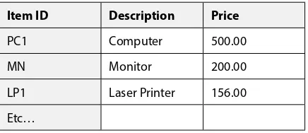
The following table shows an extract from the records of a food store. It shows CUSTOMERs and the PRODUCTs that they purchased.
a) how each occurrence of CUSTOMER is related to occurrence(s) of PRODUCT b) how each occurrence of PRODUCT is related to occurrence(s) of CUSTOMER
Exercise 2 feedback
a) CUSTOMER is related to occurrence(s) of PRODUCT
CUSTOMER PRODUCT
Jones Eggs
Smith
Khan Butter
Lewis Apples
b) PRODUCT is related to occurrence(s) of CUSTOMER
Jones Eggs
Smith Butter
Khan
Lewis Apples
A practical introduction using Oracle SQL Entity Relationships
If there is a relationship between an occurrence of one entity type and an occurrence of another entity type, then it is shown on the entity relationship diagram as a line linking the two entity symbols. The relationship between the two entities should be labelled by using a suitable verb. For example the relationship “STUDENT Studies a COURSE” would be represented as follows:
As it is important to consider a relationship from both directions you should also label the relationship from COURSE to STUDENT as follows:
The relationship labels should be positioned as above, near to the relevant entities to aid readability.
Always use UPPER case text to label entities and lower case text to label relationships.
Exercise 3
Label the following relationship:- CUSTOMER receives INVOICE from the direction of INVOICE to CUSTOMER.
Exercise 3 feedback
INVOICE is sent to CUSTOMER
2.3
Relationship cardinality
Once you have established a relationship between two entity types it is important to consider how many occurrences of one entity could be related to the other entity. This is referred to as “cardinality”.
There are three types of relationship cardinality:
One to One abbreviated as 1:1 One to many abbreviated as 1:M
Many to Many abbreviated as M:M or M:N
A practical introduction using Oracle SQL
25
Entity Relationships
Using the earlier example of the relationship between STUDENT and COURSE, consider the relationship from the STUDENT’s viewpoint. You can say that a student can study a course and if you then consider the relationship from the COURSE viewpoint, you can say that a COURSE can be studied by many STUDENTs. This would be a “one to many” (1:M) relationship and would be drawn on the ERD as follows:
A one to many (1:M) relationship
The “crow’s foot” symbol is used to represent many and is placed at the “many” end of the relationship. The relationship would be read formally as “a student studies one and only one course and a course is studied by one or many students”. If you now reconsider the relationship between STUDENT and COURSE but want to be able to show that a student may study more than one course, you now need to alter the relationship to show as a “many to many” (M:M or M:N). A M:N relationship is sometimes written as M:M though M:N is preferred so as to indicate that the number of occurrences at one end of the relationship can be different from number at the other end of the relationship. This is drawn on the ERD as follows:
Click on the ad to read more Click on the ad to read more Click on the ad to read more Click on the ad to read more Click on the ad to read more Click on the ad to read more Click on the ad to read more Click on the ad to read more Click on the ad to read more
American online
LIGS University
▶
enroll
by September 30th, 2014
and
▶
save up to 16%
on the tuition!
▶
pay in 10 installments / 2 years
▶
Interactive
Online education
▶
visit
www.ligsuniversity.com
to
find out more!
is currently enrolling in the
Interactive Online
BBA, MBA, MSc,
DBA and PhD
programs:
Note: LIGS University is not accredited by any
nationally recognized accrediting agency listed
by the US Secretary of Education.
A practical introduction using Oracle SQL Entity Relationships
A many to many (M:N) relationship
There are now crow’s foot symbols at both ends of the relationship, because they are both “many” ends. This relationship would now be read as “a student studies one or many courses and a course is studied by one or many students”.
The final cardinality type that needs to be examined is for the “one to one” relationship. If a STUDENT is assigned a LECTURER as a supervisor and the LECTURER only supervises one student, you can show this as follows on the ERD:
A one to one (1:1) relationship
In this case the relationship would be read as “a student is supervised by one and only one lecturer and a lecturer supervises one and only one student.
Exercise 4
Draw a single Entity Relationship Diagram showing the four entities and three relationships for each of the following:
a) An ID CARD is issued to a STUDENT A STUDENT receives an ID CARD
b) A STUDENT studies one or more MODULEs A MODULE is studied by one or more STUDENTs
c) A MODULE LEADER leads many MODULEs A MODULE has one MODULE LEADER
A practical introduction using Oracle SQL
27
Entity Relationships
2.4
Relationship optionality
When describing an entity relationship you need to record the fact on the ERD that in some cases an occurrence of an entity type may not always be present, in which case the relationship is said to be
optional. Using the previous cardinality example, the model states that a lecturer supervises a student. However, what if some lecturers do not act as supervisors to students? In this situation an occurrence of LECTURER will not always be related to an occurrence of STUDENT so it will be an optional relationship. However, if you consider the relationship from the STUDENT perspective it is still present as all students must have a supervising LECTURER.
To denote that a relationship can be optional a small circle is included on the relationship line at the end that is optional. The following shows the optional 1:1 relationship between STUDENT and LECTURER:
A one to one (1:1) relationship with optionality.
The circle might be viewed as the letter O for optional but it is best considered as a zero.
As you will recall, you always consider the relationship from the perspective of a single occurrence of each participating entity. This diagram would be read as “a student is supervised by one and only one lecturer and a lecturer supervises zero or one student”. Notice that the optionality is placed at the opposite end of the relationship to the entity on which you are concentrating. From the STUDENT end of the relationship, this diagram shows that a STUDENT is always supervised by a LECTURER.
Referring to the previous M:N relationship between STUDENT and COURSE which shows a student studies one or many courses and a course is studied by one or many students, could there be optionality in this relationship? Consider this from both ends of the relationship; firstly do all students study a course? Secondly are all courses studied by students?
A practical introduction using Oracle SQL Entity Relationships
This optionality can now be shown on the ERD as follows:
A many to many (M:N) relationship with optionality
The alternative to an optional relationship is a mandatory relationship. If the relationship is mandatory i.e. where there will always be at least one occurrence of the entity type, this is usually shown by a short vertical line | on the relationship. If you recall that the O can be said to represent a zero, then the | can be taken to represent the number one. The relationship as drawn above therefore shows the minimum and the maximum cardinality for each direction of the relationship.
It is helpful to think of the inner relationship symbol as the minimum and the outer symbol as the maximum number of occurrences. In the example above the inner symbols used ore o and | and the crow’s feet are the outer symbols.
The relationship is read as follows:
One STUDENT studies one or more COURSEs
A practical introduction using Oracle SQL
29
Entity Relationships
The reading of the relationship starts with “one” whatever the cardinality at that end is. Always read the relationship in
BOTH directions to ensure you have correctly identified the cardinality and optionality for both ends of the relationship.
It is important to label relationships clearly. If you do not, readers may misinterpret the relationship and choose the wrong cardinality or optionality. For example, the following pair of entities is shown to have two different relationships, each requiring different cardinality and optionality values.
LECTURER
STUDENT
teaches
is taught by
Different relationships
Exercise 5
Here is a revised version of Exercise 4. The relationships have now been altered to include optionality in some areas. Produce an amended ERD to reflect this.
a) An ID CARD is issued to a STUDENT A STUDENT receives an ID CARD
b) A STUDENT studies one or more MODULEs
A MODULE is studied by zero, one or more STUDENTs
c) A MODULE LEADER leads many MODULEs A MODULE may have a MODULE LEADER
A practical introduction using Oracle SQL Entity Relationships
Exercise 6
Below are the exercises that you modelled in the last chapter. Using the entities you identified, draw ERDs showing all the entities and relationships for each scenario. Remember to use meaningful relationship names and determine the cardinality and optionality.
1. A large business consists of a number of divisions. Each division has a number of departments. Each employee works for a department.
2. A car hire company’s customers make bookings to hire its cars. When a booking is made it is for a specific model of car and includes the collection and return dates. At the time of the booking the company may assign a particular car, however at the time of collection a different car may be provided. The company needs to keep records of which car each customer actually hired.
Exercise 6 feedback
1.
A practical introduction using Oracle SQL
31
Complex relationships
3 Complex relationships
On completion of this chapter you should be able to:
• build a more complex entity relationship diagram
• identify relationships that have data associated with them • model entities in which occurrences are related to each other.
3.1 Introduction
The previous chapters have introduced you to the basic concepts of the entity relationship modelling technique. You are now going to look at some modelling situations in more detail. In particular you are going to consider a technique to enable you to deal with modelling relationships that have data associated with them. You will also be introduced to extended entity-relationship modelling techniques (sub types and exclusive relationships) that can be used in more complex situations.
Click on the ad to read more Click on the ad to read more Click on the ad to read more Click on the ad to read more Click on the ad to read more Click on the ad to read more Click on the ad to read more Click on the ad to read more Click on the ad to read more Click on the ad to read more Click on the ad to read more
A practical introduction using Oracle SQL Complex relationships
3.2
Associative relationships
An ERD may contain several many-to-many relationships. If you consider these many-to-many relationships in more detail you are likely to discover that they actually hold attributes of data. To understand this, consider the following example.
In a business situation an invoice showing products purchased could be represented by an INVOICE entity type related to a PRODUCT entity type as a M:N relationship shown as follows:
Many to many relationship between INVOICE and PRODUCT
If you consider the data attributes that might be stored for INVOICE, these might include the invoice number (unique identifier), invoice date and customer code. The PRODUCT attributes would include product code, description and unit price. However, this combined set of attributes does not actually represent the complete set of data needed to represent an actual business invoice, as you cannot identify the quantity purchased of a product for a specific invoice.
This is clearly data that needs to be recorded, but it cannot be recorded as an attribute of either of the relationship entities. In fact, it needs to be placed somewhere else, as will be explained shortly. It is desirable to show this hidden information on the ERD. This is accomplished by resolving the many-to-many relationship and capturing the data in a third entity type. This new entity links together a single occurrence of each of the other two entities.
A practical introduction using Oracle SQL
33
Complex relationships
The new link entity can now be used to hold the quantity purchased of a product. It will also need other attributes which will be used as the entity identifier and also to link to the appropriate occurrence of the INVOICE and PRODUCT entities; this will be explained later. In this example the new link entity has been called ITEM as it represents an invoice item line. However, it is not always easy to think of a meaningful name for the link entity, although if the original relationship name was meaningful this may provide the answer. Alternatively, if you consider the purpose of the new entity and, in particular, what attributes will be included it should make it easier to choose one. If you cannot identify a suitable name, you could combine the two entity names e.g. INVOICE and PRODUCT.
A M:N relationship is replaced with a new entity and two 1:M relationships. The new link entity uses both original entity identifiers together to form its identifier.
Exercise 1
For a car hire business consider one occurrence of CUSTOMER and one occurrence of a HIRE CAR. What data might you need to record about that particular customer’s use of the hire car?
Exercise 1 feedback
The main data values to be recorded would be the collection date and return date, though you may choose to store other information as well.
Exercise 2
a) Resolve the many-to-many relationship between CUSTOMER and HIRE CAR. Make sure that you show the cardinality of the relationships correctly. First choose a suitable name for the new link entity. Then you can decide on sensible names for the relationships.
A practical introduction using Oracle SQL Complex relationships
Exercise 2 feedback
Based on Exercise 1 you may choose to call the new entity type RENTAL or HIRE.
a)
If it is likely that a car may not be hired out, the optionality symbol could be placed on the relationship between hire car and rental at the rental end of the relationship.
b) CUSTOMER ( Customer no., booking date, customer name,…..)
HIRE CAR ( Car reg., model, …)
c) RENTAL (Customer no., collection date, return date, Car reg, …)
3.3
Link entity identifier
As mentioned in Chapter 1, all entities must have a unique identifying attribute, and those looked at so far have all been single attributes. However this is not appropriate for a link entity.
www.mastersopenday.nl
Visit us and find out why we are the best!
Master’s Open Day: 22 February 2014
Join the best at
the Maastricht University
School of Business and
Economics!
Top master’s programmes
• 33rd place Financial Times worldwide ranking: MSc
International Business
• 1st place: MSc International Business
• 1st place: MSc Financial Economics
• 2nd place: MSc Management of Learning
• 2nd place: MSc Economics
• 2nd place: MSc Econometrics and Operations Research
• 2nd place: MSc Global Supply Chain Management and
Change
Sources: Keuzegids Master ranking 2013; Elsevier ‘Beste Studies’ ranking 2012; Financial Times Global Masters in Management ranking 2012
A practical introduction using Oracle SQL
35
Complex relationships
It is unlikely that there will be a suitable natural single attribute for identifying the new entity. The identifier for a CUSTOMER is its Customer no. and the identifier for a HIRE CAR is its Car Registration. However, neither of these identifying attributes can be used alone in the new entity as they may have repeat occurrences, as shown in the example tables below. In this situation, the identifier is usually formed by combining the identifiers from the original pair of entities.
Let us apply this to the car hire system that was modelled in Exercise 2. The unique identifier that will identify a single occurrence of RENTAL will be the combination of Customer no. and Car Registration.
Now, if you examine some occurrences of these entities, you can clearly see that a combined identifier is needed to uniquely locate a specific RENTAL of a particular HIRE CAR by a CUSTOMER.
What issue might arise relating to the identifier if a customer could rent a car more than once?
If the following sample data is
used:-CUSTOMER
Customer no. Name
C101 M Jones
C102 A Khan
HIRE CAR
Car reg. Model
A77 NWW Peugeot 205Gti
F123 XWX Subaru Imprezza
RS101 Ford Focus RS
RENTAL
Customer no. Car reg. Collection date Return date
C101 A77 NWW 10-Jan-2015 15-Jan-2015
C102 A77 NWW 3-Mar-2015 3-Mar-2015
C101 F123 XWX 7-Apr-2015 8-apr-2015
A practical introduction using Oracle SQL Complex relationships
If customer C101, having hired car A77 NWW in January 2015, then hired it again in March, including the data in the table above would cause the combined identifier C101and A77 NWW to be duplicated, so a further attribute, collection date, would be needed as part of the identifier to uniquely identify the occurrences.
RENTAL
Customer no. Car reg. Collection date Return date
C101 A77 NWW 10-Jan-2015 15-Jan-2015
C102 A77 NWW 3-Mar-2015 3-Mar-2015
C101 A77 NWW 7-Mar-2015 9-Mar-2015
C101 F123 XWX 7-Apr-2015 8-apr-2015
C102 RS101 11-Jun-2015 22-Jun-2015
Exercise 3
Model the following situation:
The small independent “Yorkshire Cinema” has two screens, Screen one and Screen two. Only one film each evening is shown on each screen. Cinemagoers can make online bookings for films currently being screened. To make a booking the person selects the screen and the screening date. A booking reference number is emailed to the purchaser. Cinemagoers sometimes enquire about current films and information about the film actors appearing in them, film length etc. is supplied.
The entity types have already been identified for this system as SCREEN, CINEMAGOER, BOOKING, SCREENING, FILM and ACTOR.
a). Draw the ERD for this case study including these entity types and the relationships linking them. Remember to name the relationship from both entity types involved and also to include the cardinality and any potential optionality. There is one many-to-many relationship; resolve this by including a link entity.
A practical introduction using Oracle SQL
37
Complex relationships
Exercise 3 feedback
This ERD shows the entity types with two attributes and their data types (data types will be discussed in Chapter 6), the identifiers are shown underlined. This is made possible as the attributes were entered into the case tool.
The many-to-many relationship between FILM and ACTOR has been resolved by including the link entity CAST MEMBER.
3.4
Recursive relationships
So far you have concentrated on identifying and modelling relationships between pairs of entity types. Most of these relationships will be to-many, a few might be many-to-many and some might be one-to-one. You have also discovered how to resolve many-to-many relationships that contain data which is of interest in the situation being modelled.
You may also encounter entities that are related to themselves. To be more specific, occurrences of the entity type are related to other occurrences of the same entity type. This is called a recursive relationship.
A practical introduction using Oracle SQL Complex relationships
This gives rise to a hierarchical relationship within this single EMPLOYEE entity type. This can be represented graphically using a hierarchy diagram, as follows:
A practical introduction using Oracle SQL
39
Complex relationships
This hierarchy diagram clearly shows that an occurrence of the entity EMPLOYEE, say Dean, manages one or more other occurrences of EMPLOYEE. Another occurrence of the entity, a Head of department, also manages one or more other occurrences of the same entity, Lecturer.
To show this 1:M recursive relationship on an ERD you draw a relationship line starting and finishing at the entity, as follows:
Modelling a recursive relationship
This relationship would be read from the ‘one’ end as, “an EMPLOYEE manages one or more other EMPLOYEEs”. Reading the relationship from the other end, you can say an EMPLOYEE is managed by one and only one EMPLOYEE.
Following a more detailed analysis, this model does not accurately model the ‘manages’ relationship between occurrences of university employees. The reason for this is that there is an optional participation in the relationship. The Vice-chancellor in effect manages all employees. However, the Vice-chancellor is not managed by another member of staff. (His/her activity is monitored by a Board of Governors, but the Governors are not occurrences of the entity EMPLOYEE). Similarly, there are many individual lecturers who do not manage any other staff. Consequently, this optionality needs to be modelled on the ERD:
Recursive relationship with optionality
A practical introduction using Oracle SQL Complex relationships
Exercise 4
Model the following situation:
A car manufacturer makes a number of different models of car, each of which comprises many components. Some components are used in many models. A number of suppliers supply the components and each supplier supplies a number of different components. In some cases components are used to build other components, e.g. pistons, crankshaft etc. are used to build an engine which is a component of a car. Each component is checked by the quality inspector before use; the inspector will be responsible for checking many different components.
Exercise 4 feedback
The recursive relationship is read as “a component may be used in zero, one or many components and a component may use zero one or many components”.
3.5
Sub types
A practical introduction using Oracle SQL
41
Complex relationships
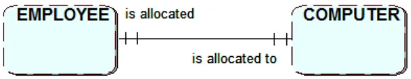
E.g. An employee at a car hire company could be modelled using sub types to show the different categories of employee.
Click on the ad to read more Click on the ad to read more Click on the ad to read more Click on the ad to read more Click on the ad to read more Click on the ad to read more Click on the ad to read more Click on the ad to read more Click on the ad to read more Click on the ad to read more Click on the ad to read more Click on the ad to read more Click on the ad to read more Click on the ad to read more
Get Help Now
Go to www.helpmyassignment.co.uk for more info
Need help with your
dissertation?
A practical introduction using Oracle SQL Complex relationships
3.6
Exclusive relationships
Sometimes two or more relationships are mutually exclusive, e.g. a VEHICLE may be undergoing a SERVICE or an INSPECTION but not both at the same time. This is shown by an arc symbol pointing towards the mutually exclusive options.
3.7 Summary
Here is a summary of the main terminology relating to entities and relationships that you have now been introduced to:
Entity A data object of interest to the system
Attribute A property of an entity
Identifying attribute An attribute or combination of attributes that uniquely identifies an entity occurrence
Relationship An association between two entities
Cardinality The number of occurrences in one entity that can have a relationship with the occurrences in another entity
one to one 1:1
one to many 1:M or 1:m
many to one M:1 or m:1
many to many M:N or m:n (or M:M)
Optionality Participation in a relationship
Exercise 5
1. A car hire company takes bookings from customers for hire vehicles. A booking may relate to a group of other bookings i.e. when a customer has made multiple bookings for vehicles to be collected at the same time. Vehicles receive regular services. When vehicles are returned following a hire they may be inspected. Following an inspection the vehicle may need repairs. A repair will result in further inspections.
A practical introduction using Oracle SQL
43
Complex relationships
Exercise 5 feedback
a)
Click on the ad to read more Click on the ad to read more Click on the ad to read more Click on the ad to read more Click on the ad to read more Click on the ad to read more Click on the ad to read more Click on the ad to read more Click on the ad to read more Click on the ad to read more Click on the ad to read more Click on the ad to read more Click on the ad to read more Click on the ad to read more Click on the ad to read more
By 2020, wind could provide one-tenth of our planet’s electricity needs. Already today, SKF’s innovative know-how is crucial to running a large proportion of the world’s wind turbines.
Up to 25 % of the generating costs relate to mainte-nance. These can be reduced dramatically thanks to our systems for on-line condition monitoring and automatic lubrication. We help make it more economical to create cleaner, cheaper energy out of thin air.
By sharing our experience, expertise, and creativity, industries can boost performance beyond expectations.
Therefore we need the best employees who can meet this challenge!
The Power of Knowledge Engineering
Brain power
A practical introduction using Oracle SQL Logical Database Design
4 Logical Database Design
On completion of this chapter you should be able to:
• convert an ERD into a logical database design • identify primary and foreign keys
• provide a logical design for relationships of different cardinalities.
4.1 Introduction
Once you have completed the conceptual design and have produced your Entity Relationship Diagram you can move on to the next stage in the database development lifecycle, namely Logical Design. You will produce an initial logical design for a database in this chapter, and in the next chapter you will study the process of Normalisation. This is used to check the structure of your database tables with a view to eliminating data redundancy and ensuring that you have produced an efficient set of tables to be implemented in the final design stage Physical Design.
In this chapter you will learn how to turn an Entity Relationship Diagram into a logical design comprising a set of relations (not to be confused with relationships). This design will become a set of tables suitable for implementation using a relational database management system such as Microsoft Access, MySQL or Oracle. A relation is a table-like structure made up of columns (attributes) and rows. Each column has a domain name and this defines the nature of the data to be held.
4.2 Relations
The relational database derives from the relational model which is based on mathematical concepts introduced by (E.F. Codd, 1970). A relation is a logical construct that is similar to a table. (Please note that a relation is not the same as a relationship). However, as you will see below, the term relation can be used in a slightly different context.
A relational database just stores data, and nothing more, inside tables. Any processing of the data is done by using a data manipulation language which works on the tables to output information or alter values stored within the tables. The most commonly used data manipulation language used for accessing relational databases is the Structured Query Language (SQL).
Although SQL has an American National Standard (ANSI) there are some differences between the implementations used by the different database management systems.
A practical introduction using Oracle SQL
45
Logical Database Design
Here is an example of a relation for the entity type CUSTOMER:
CUSTOMER (Customer_no., name, address, date_of_birth, ………)
Customer no. is the unique identifier, but in the relation it is referred to as the Primary Key (PK).
Just as all entity types have a unique identifier, all relations have a Primary Key.
The alternative definition of a relation is the relational database table itself. However, to avoid confusion in this context you would normally refer to it as a ‘table’. You can now visualise the relation CUSTOMER as a table showing occurrences of entity types as follows:
Customer_no. Name Address Date_of_birth …
C4347888 Amin Khan 103, Short Street, Wakefield WYS6 2EG 13-Jan-1987
C8365872 Sarah Jones 13, Gain Lane, Sheffield SS7 1AX 09-Dec-1980
Although all tables consists of rows and columns, a relational database table has to satisfy the following rules.
- Each row of the table (also called a ‘tuple’ – sounds like ‘couple’) is associated with exactly one entity occurrence so no two are identical (although column values other than the primary key could be identical)
- Rows can be in any order
- Each table column contains attribute values.
4.3 Keys
Keys play a vital role in database design and have to be identified and used correctly. The following terminology is used in association with relational database keys:
- a key uniquely identifies an entity occurrence: it is the entity identifier - a primary key is the key ‘chosen’ for a given relation / table
- a candidate key is a ‘possible’ primary key (several candidate keys may exist for a relation) - a compound key is a key consisting of two or more attributes.
In the following relation:
VEHICLE (vehicle_identification_no., registration_no., vehicle_make, vehicle_model, …)
A practical introduction using Oracle SQL Logical Database Design
(Note that from now on, spaces in the names of attributes will be replaced by underscore characters like this: An_attribute_name_of_several_words. This is because when the design is implemented the database management system will not allow column names which include spaces.)
Exercise 1
Which candidate key from the VEHICLE relation above would you choose as the primary key and why?
Exercise 1 feedback
A manufacturer-assigned vehicle_identification_no. would be chosen, as the vehicle registration_no. may change over the lifetime of the vehicle. Though depending on the use of the system, vehicle registration no. may be a better choice, i.e. in a car hire business.
Exercise 2
a) Consider the following ERD:
Choose a Primary Key for each of the entities.
b) Which of these applies to the key for BOOKING?
- a compound key - a candidate key
Exercise 2 feedback
a) Primary key for entity type CUSTOMER would be Customer_no.
Primary key for entity type CAR would be vehicle_identification no. or registration number.
Primary key for entity type BOOKING would be Customer_no. and vehicle_identification no. together.
b) A compound key.
4.4
Identifying relations
A practical introduction using Oracle SQL
47
Logical Database Design
In order to establish the relationships between entities you will make use of keys. In order to do this a new type of key, the Foreign Key (FK), is needed.
For example, earlier you modelled the one-to-many relationship between CUSTOMER and BOOKING on the conceptual level. To achieve a logical design for the tables in your database you will need to produce two relations: CUSTOMER and BOOKING. In order to take into account the link between these two relations you must copy the primary key of CUSTOMER (which is at the “one-end” of the relationship) into the relation BOOKING (at the “many-end” of the relationship). So the Customer_no. becomes a foreign key in the relation BOOKING. The following diagram emphasises this:
This ERD would result in the following two relataions:
CUSTOMER (Customer no., customer name, customer_address, …) BOOOKING (Booking ref., Booking_date, Customer_no, …)
A practical introduction using Oracle SQL Logical Database Design
In order to identify all the relations and their keys you need to work methodically from your ERD, checking each relationship in turn in order to produce a set of ‘skeleton relations’. A skeleton relation
shows only the name of the relation and all of the keys, i.e. the primary key and any foreign keys. The additional attributes can be added at a later stage to form a completed set of relationships.
A skeleton relationship for the booking from above is shown as follows:
BOOKING (Booking ref., Customer_no)
It is important to ensure that keys are clearly identifiable, as such the following notation is used in printed text when showing relations:
Primary key – bold or underline or both e.g. Student_ID
Foreign key – italicise e.g. Course_Code
In handwritten text you can use a dotted underline for a foreign key.
In handwritten text a key that is both a primary key and a foreign key can be underlined twice, once with dotted and once with normal underline.
Also note that if underlining a compound key consisting of 2 or more attributes, ensure the underline under them is continuous e.g. order_no, line_no
Whichever notation you choose, you should ensure that you use it consistently.
A foreign key is an attribute (or combination of attributes) in one relation which exists as a primary key in some other relation.
Remember for a 1:M relationship with no optionality at the one end, the primary key from the one end of the relationship goes in at the many end as the foreign key.
Exercise 3
A practical introduction using Oracle SQL
49
Logical Database Design
Exercise 3 feedback
As a customer may make many bookings you would need to make provision to hold all of the Booking references in customer. This is not practical, as you would need to decide the maximum number of bookings to allow for, and if this number altered it would need a change to the implemented table structure. If a large number of Booking Refs. were allowed for this could also result in many of them being left empty in the customer row. Finally, it is much more difficult to search through a repeating list of attributes, so whilst it is technically possible to store repeating attributes this is not normally acceptable so you should avoid doing this.
Exercise 4
a)
Which of the following would you do to represent the above relationship between a hire CAR and CUSTOMER on the logical level?
• put Car_reg. as an attribute of CUSTOMER • put Customer_no. as an attribute of CAR • both
• neither
b)
What would be the skeletal logical relations in this case? Choose a sensible notation for the primary and foreign keys.
Exercise 4 feedback
a) put Car_reg. as an attribute of CUSTOMER
b) CAR (Car_reg.)
Car_reg. is the primary key in CAR
CUSTOMER (Customer_no., Car_reg.) Car_reg becomes a foreign key in CUSTOMER.
4.5
Resolving many-to-many relationships
A practical introduction using Oracle SQL Logical Database Design
For example, the following ERD will require three skeletal relations:
STUDENT (Student_id)
MODULE (Module_Id)
STUDY (Student_id, Module_id)