Contents
1
Product information ... 3Diversity and quality ... 3
Why specify angular contact ball bearings? ... 3
Why specify SKF angular contact ball bearings? ... 3
Advantages by design with SKF Explorer bearings ... 4
Technical improvements ... 4
Identification symbols ... 5
Advantages for your design: higher performance with SKF Explorer bearings ... 6
Longer service life ... 6
New designs with smaller bearings ... 7
New designs with higher power density ... 7
Efficient in all industrial segments ... 8
2
Recommendations ...10Selection of bearing size ... 10
Bearing life ... 10
Load carrying capacity of paired single row bearings ... 11
Equivalent dynamic bearing load ... 12
Equivalent static bearing load ... 12
Minimum load ... 12
Determining axial force for bearings mounted singly or paired in tandem ... 13
Design of bearing arrangements ... 14
Mounting and dismounting ... 16
Mounting ... 16
Dismounting ... 17
Service for a lasting partnership ... 18
3
Product data ...19Single row angular contact ball bearings ... 19
General bearing data ... 19
Assortment ... 22
Product table ... 24
Double row angular contact ball bearings ... 34
General bearing data ... 34
Assortment ... 38
Product tables ... 40
Other SKF angular contact ball bearings ... 46
The SKF brand now stands for more than ever before, and means more to you as a valued customer.
While SKF maintains its leadership as the hallmark of quality bearings throughout the world, new dimensions in technical advances, product support and services have evolved SKF into a truly solutions-oriented supplier, creating greater value for customers.
These solutions encompass ways to bring greater productivity to customers, not only with breakthrough application-specific products, but also through leading-edge design simulation tools and consultancy services, plant asset efficiency maintenance programs, and the industry’s most advanced supply management techniques.
The SKF brand still stands for the very best in rolling bearings, but it now stands for much more.
1
Why specify angular
contact ball bearings?
High rotating speeds, combined radial and axial loads, a high degree of stiff-ness and running accuracy – these are the application requirements where angular contact ball bearings excel. The great variety of applications and operating conditions calls for unique bearing solutions made possible by a wide range of angular contact ball bearings.
Why specify SKF angular
contact ball bearings?
Because SKF is your reliable, expert source for angular contact ball bear-ings. Because SKF has a wide range of types and variants unmatched any-where else. Because when you work with SKF you don’t have to settle for any unfavourable compromises. Since the introduction of the BE bearings in 1984, SKF single row angular contact ball bearings have set the standard. Since then, time certainly hasn’t stood still, and neither has SKF.
The best example: the SKF Explorer single row and double row angular
Diversity and quality
contact ball bearings offer a completely new level of performance. With SKF angular contact ball bearings, you bene-fit in a number of ways:
High performance
They have a high load carrying capacity and thus allowing smaller bearings to be used while still providing long ser-vice life.
Quieter and cooler running
With their optimal internal geometry, they run quieter and cooler and can provide longer maintenance intervals.
Precise shaft guidance
Due to precision manufacturing pro-cesses, almost all SKF angular con-tacts meet closer tolerances, to enable a smoother, truer running shaft with less heat and less vibration.
High temperature capability
They can withstand relatively high operating temperatures without sig-nificant loss of dimensional stability.
Universal matching
At SKF, universally matchable single row angular contact ball bearings are standard. These bearings simplify assembly and can also increase the quality of your products. Our selection of clearance and preload classes covers almost all possible application requirements.
Integral sealing solutions
Double row angular contact ball bear-ings are available with integral seals and shields. These bearings are sup-plied with grease and do not require maintenance.
Standard solutions
It will be hard to find an application for which there’s no standard SKF bearing readily available from our vast selection and enormous variety.
Customer satisfaction
Now you can build additional value into your products with SKF Explorer bear-ings. Your customers will definitely be impressed by the low operating costs, reliability and long service life of your machines – no doubt in part to your use of SKF bearings.
angular contact ball bearings are less sensitive to potential axial overloading.
More precise shaft guidance
SKF Explorer single row bearings are manufactured to P5 running accuracy. SKF Explorer double row bearings are manufactured to P6 running accuracy.
Better ball quality
The balls used in SKF Explorer angular contact ball bearings are one ISO grade better than before. The more uniform ball diameter helps to improve run-ning accuracy even at high speeds, while reducing noise and operating temperature.
New cages
SKF Explorer single row angular con-tact ball bearings have solid cages At SKF we’re continuously working to
improve the performance and durabil-ity of our products. And with the new SKF Explorer angular contact ball bearings, we think you’ll notice the difference immediately. These bear-ings can provide:
• Even longer service life, • Even higher reliability, • Even more performance.
The following pages will describe the improvements we have made to our angular contact ball bearings in the 72 B and 73 B series and in the 32 A and 33 A series, of course also for the bearings in the 52 A and 53 A series, which are identical to the correspond-ing 32 A and 33 A bearcorrespond-ings.
Technical improvements
Improved materials
SKF Explorer angular contact ball bearings are manufactured from an extremely high quality bearing steel with a very low oxygen content and a minimum number of impurities. The rings are manufactured from forged or cold rolled blanks.
All rings are heat treated to provide dimensional stability up to 150 °C (300 °F). The advantage: SKF single row angular contact ball bearing sets hold their original built-in clearances and preloads for extended operating
times (➔diagram ).
Improved inner geometry
Computer-aided design and manufac-turing programs permit almost unde-tectable geometrical changes in the bearing. These small but effective changes in the bearing’s geometry lead to measurable improvements in
1
Advantages by design with
SKF Explorer bearings
0,015 0,010 0,005 0
-0,010 -0,015 -0,020 -0,005
10 100 1000 10 000
1
Diagram
Operating hours
Clearance, mm
Pr
eload, mm
Examples: 7307 BE set, Fa/Fr= 1,23, C/P = 29, operating temperature 110 °C (230 °F)
3310 A/C3, Fa/Fr= 1,23, C/P = 19, operating temperature 80 °C (175 °F)
Change of the residual axial bearing clearance/preload during operation SKF Explorer 7307 BECB set
SKF previous standard 7307 BECB set
SKF Explorer 3310 A/C3 SKF previous standard 3310 A/C3
SKF Explorer 7307 BEGA set SKF previous standard 7307 BEGA set
1
to better withstand high accelerations. Machined brass cages are manufac-tured to closer tolerances and have been improved to provide better ball guidance and maximize the effects of the lubricant under all operating condi-tions.
SKF Explorer double row angular contact ball bearings are available as standard with a newly-developed crown cage made of sheet steel.
Effective seals
Double row angular contact ball bear-ings are available with seals or shields. Shielded SKF Explorer bearings (➔fig
) use a new shield design. A new simple labyrinth keeps contaminants out and retains grease in the bearing cavity.
Identification symbols
SKF Explorer angular contact ball bearings are not an extension of the assortment. They replace final variants of the previous types. And because it is easier for inventory management,
1
their part numbers remain the same. Nevertheless, SKF Explorer bearings can be recognised easily.
Packaging
SKF Explorer bearings come in a unique package, so that they can be recognised immediately as SKF Explorer bearings.
Laser inscription
A new feature of the SKF Explorer bearings is their laser inscription. It is not only more legible, but also more environmentally friendly because acids are no longer required for etch-ing. It also permits individual mark-ings. Depending on the requirements in Quality Assurance, the bearings can be traced precisely.
SKF Explorer angular contact ball bearings
• Improved materials
• Optimized internal geometry • Higher precision
• Higher ball quality • Improved cages
• For universal matching in bearing sets
• New shields for double row bearings
Shielded SKF Explorer double row angular contact ball bearing
1
Fig
Increase
power output
of existing designs
Avoid costly redesign by using an SKF Explorer bearing of equal size to:
• Increase power density (output) • Increase speeds
• Increase loads
Increase
power density
of new designs
Use a lower cross section SKF Explorer bearing with the same outside diameter to:
• Increase shaft size • Achieve a stiffer design
• Operate at the same or higher speeds
Maintain power output
of new designs
Use a smaller SKF Explorer bearing to:
• Reduce overall dimensions to save on material cost and weight
• Reduce heat generation • Increase speeds
Increase service life
of existing designs
Don’t need to increase power output? Use an SKF Explorer bearing of equal size to:
• Increase the reliability • Reduce vibration • Reduce heat generation • Increase service intervals • Increase machine uptime
Advantages for your design: higher
performance with SKF Explorer
bearings
The technical improvements incorpor-ated in SKF Explorer angular contact ball bearings can provide one of four general design benefits. For existing designs, you can either increase ser-vice life or increase power output. For new designs, you can maintain power output or increase power density. The option you chose depends on the cus-tomer and the application’s require-ments. Whichever option you chose, new SKF Explorer angular contact ball bearings will provide increased service
life and decreased maintenance costs for your application.
Longer service life
The extended life of SKF Explorer angular contact ball bearings can be demonstrated best with the use of an example. The shafts of a twin screw compressor are supported radially with cylindrical roller bearings and axial-ly with a matched set of angular
con-tact ball bearings (➔fig ). With the existing design, the axial bearing of the drive shaft is the critical point. The calculated life of this bearing arrange-ment, consisting of three 7308 BEGAP bearings amounts to 50 900 hours; calculated in accordance with the SKF Life Method. With the new SKF Explorer bearings, the calculated life amounts to 96 200 hours. This means a life 1,9 times longer under otherwise identical conditions and without any changes in the design.
Comparison of SKF Explorer and previous standard bearings – possible downsizing
1
New designs with
smaller bearings
In many cases where 73 B series bearings are used, it will be possible to use 72 B series bearings in the future. Even with a smaller bearing, a longer bearing service life will be pos-sible. Table shows some suitable examples.
Without changes to the shaft, bearing arrangements can also be designed more compactly. SKF Explorer bearings permit lighter structures with the same capacity.
New designs with higher
power density
If the outside diameter of the bearing remains unchanged, the transition from 73 B series bearings to 72 B series bearings will permit the use of stronger shafts (➔table ).
With otherwise unchanged parts, more rigid designs with higher power density are possible. And the service life of the bearing will be increased significantly.
1 1
1
Fig
Twin-screw compressor bearing arrangement
Previous SKF Explorer Cross section Life increase standard bearing AExpl ×
100 L10m,Expl
bearing Aprev L10m,prev
Same bore 7306 BE 7206 BE 64 % 1
diameter
7308 BE 7208 BE 63 % 1,2
7319 BE
7219 BE 51 % 1,1
Same outer 7304 BE 7205 BE 84 % 1,7
diameter
7308 BE 7210 BE 70 % 1,6
7313 BE 7216 BE 63 % 1,5
1
Table
Efficient in all industrial
segments
Lower friction, quieter running and, above all, improved reliability in com-plex applications with combined loads make SKF angular contact ball bear-ings indispensable in many areas.
Long service life and reliable perform-ance have earned SKF angular con-tact ball bearings an excellent reputa-tion in a variety of industries ranging from gearboxes to turbines.
Nevertheless, the most common applications for angular contact ball bearings are pumps and compressors. These applications are not just the most common, they are also the most demanding. For example, the bearings
used in both pumps and compressors must be able to accommodate com-bined axial and radial loads, high speeds, poor lubrication and con-taminated conditions.
The improvements made to the new SKF Explorer bearings were aimed primarily at the demanding require-ments of both pumps and compres-sors. For these applications a recom-mended product range is available.
Industrial segments
• Fluid machinery:
Pumps, compressors, blowers, ventilators, turbines
• Automotive engineering: Drives, clutches, gearboxes, wheel bearings, components • Industrial drives and drive
motors
• Printing machines • Textile machines • Material handling
Requirements
• Long service life
• High load-carrying capacity and high speeds
• High degree of stiffness
• High degree of running accuracy • Low heat generation
• Quiet running • Technical support
Solution
1
Selection of bearing size
Bearing life
The life-extending improvements, embodied in SKF Explorer bearings can best be understood using the SKF Life Method. This life calculation method constitutes an extension of the fatigue life theory developed by Lundberg and Palmgren and is better able to predict bearing life. The life method, first presented by SKF in 1989 is standardized today in ISO 281:1990/Amd 2:2000. The modified rating life for angular contact ball bear-ings can be calculated from
Lnm= a1aSKFL10
or
Lnm= a1aSKF
(
C)
3P
With a constant rotational speed, the life in operating hours can be calcu-lated from the following formula:
1 000 000
(
C)
3Lnmh= a1aSKF
60 n P
where
Lnm = SKF rating life (at 100 – n %
reliability), millions of revolu-tions
Lnmh= SKF rating life (at 100 – n %
reliability), operating hours L10 = basic rating life (at 90 %
reli-ability), millions of revolutions a1 = life adjustment factor for
reliability (➔table ) aSKF = SKF life modification factor
(➔diagram )
C = basic dynamic load rating, kN
P = equivalent dynamic bearing
load, kN
1 1
Page ... 3 Bearing size Page ... 19
Life modification factor aSKFfor angular contact ball bearings
If κ> 4, use curve for κ= 4
As the value of ηc(Pu/P) tends to zero, aSKFtends to 0,1 for all values of κ
0,005 0,01 0,02 0,05 0,1 0,1
0,2 0,2
0,5 0,5
1 1
2 2
5 10 20 50
5
aSKF
ηcP
P––u
ηcP P u ––
κ = 4 2 1
0,8
0,5
0,3
0,15
0,1
0,2
0,4
0,6
0,005 0,01 0,02 0,05 0,1 0,2 0,5 1 2
SKF Explorer bearings Other SKF standard bearings
1
Diagram
Reliability Lnm a1
%
90 L10m 1
95 L5m 0,62
96 L4m 0,53
97 L3m 0,44
98 L2m 0,33
99 L1m 0,21 1
2
Page ... 3 Bearing size Page ... 19
The basic static load rating and the fatigue load limit of a pair of bearings can be obtained by multiplying the table value C0or Puby 2.
Condition Factor ηc1)
for bearings with diameter
dm< 100 mm dm≥100 mm
Extreme cleanliness 1 1 Particle size of the order of the lubricant film
thickness. Laboratory conditions
High cleanliness 0,8 …0,6 0,9 … 0,8 Oil filtered through extremely fine filter
Conditions typical of bearings greased for life and sealed
Normal cleanliness 0,6 … 0,5 0,8 … 0,6 Oil filtered through fine filter
Conditions typical of bearings greased for life and shielded
Slight contamination 0,5 … 0,3 0,6 … 0,4 Slight contamination in lubricant
Typical contamination 0,3 … 0,1 0,4 … 0,2 Conditions typical of bearings without integral
seals, coarse filtering, wear particles and ingress from surroundings
Severe contamination 0,1 … 0 0,1 … 0 Bearing environment heavily contaminated and
bearing arrangement with inadequate sealing
Very severe contamination 0 0
(under extreme contamination values of ηccan be
outside the scale resulting in a more severe reduction
of life than predicted by the equation for Lnm)
1)The scale for η
crefers only to typical solid contaminants. Contamination by water or other fluids detrimental
to bearing life is not included. In case of very heavy contamination (ηc= 0), failure will be caused by wear,
the useful life of the bearing can be shorter than the rated life
2
Table
Guideline values for factor ηcfor different levels of contamination Bearing life can be calculated easily
using the programs found in the “SKF Interactive Engineering Cata-logue”.
Life modification factor aSKF
The SKF Life Method takes into account the complex relationships between different factors influencing bearing life. These factors have been simplified so that they can be inserted into your calculations. Diagram
contains the life modification factor for SKF angular contact ball bearings. The values are given as a function of
• the viscosity ratio κ,
• the ratio of the fatigue load limit to the applied equivalent load (Pu/P),
• the contamination level in the bear-ing (ηc).
Guideline values for the selection of ηcare given in table .
Diagram is based on the general safety factors typically associated with the fatigue load limits for other mech-anical components. The diagram is valid for lubricants without EP addi-tives. If lubricants with EP additives are used, reference should be made to the information in the SKF General Catalogue or in the “SKF Interactive Engineering Catalogue“ on CD-ROM or online at www.skf.com.
Load carrying capacity
of paired single row
bearings
The values for the basic dynamic and static load ratings as well as for the fatigue load limit quoted in the bearing table on pages 24 to33are for single bearings.
For pairs of universally matchable angular contact ball bearings the basic dynamic load ratings C obtained from the table should be multiplied by
• 1,62 for standard bearings in all arrangements and SKF Explorer bearings in face-to-face or back-to-back arrangement,
• 2 for SKF Explorer bearings in tandem arrangement.
1
2
Page ... 3 Bearing size Page ... 19
Equivalent dynamic
bearing load
Single row bearings
For single row B and BE design angu-lar contact ball bearings mounted as single bearings or paired in tandem:
P = Fr when Fa/Fr≤1,14
P = 0,35 Fr+ 0,57 Fa when Fa/Fr> 1,14
When determining the axial load Fa,
reference should be made to the section “Determining axial force for bearings mounted singly or paired in tandem”.
For pairs of bearings arranged back-to-back or face-to-face:
P = Fr+ 0,55 Fa when Fa/Fr≤1,14
P = 0,57 Fr+ 0,93 Fawhen Fa/Fr> 1,14
Frand Faare the forces acting on the
pair of bearings.
Double row bearings
For double row angular contact ball bearings in the 32 A and 33 A series:
P = Fr+ 0,78 Fa when Fa/Fr ≤0,80
P = 0,63 Fr+ 1,24 Fa when Fa/Fr > 0,80
and for double row angular contact ball bearings in the 33 DNRCBM series:
P = Fr+ 0,55 Fa when Fa/Fr≤1,14
P = 0,57 Fr+ 0,93 Fawhen Fa/Fr> 1,14
and for double row angular contact ball bearings in the 33 D series:
P = Fr+ 0,47 Fa when Fa/Fr≤1,34
P = 0,54 Fr+ 0,81 Fawhen Fa/Fr> 1,34
Equivalent static bearing
load
Single row bearings
For single row B and BE design angu-lar contact ball bearings mounted as single bearings or paired in tandem:
P0= 0,5 Fr + 0,26 Fa
If P < F then P = F. When
deter-bearings mounted singly or paired in tandem”.
For pairs of bearings arranged back-to-back or face-to-face:
P0= Fr+ 0,52 Fa
Frand Faare the forces acting on the
pair of bearings.
Double row bearings
For double row angular contact ball bearings in the 32 A and 33 A series:
P0= Fr+ 0,66 Fa
and for bearings in the 33 DNRCBM series:
P0= Fr+ 0,52 Fa
and for bearings in the 33 D series:
P0= Fr+ 0,44 Fa
Minimum load
In order to provide satisfactory oper-ation, a minimum load must be applied to the bearing arrangement. This is particularly important in high-speed applications where inertial forces of the balls and the cage as well as the friction in the lubricant influence the rolling conditions in the bearing to cause sliding movements (skidding) between the balls and race-ways.
For single row individual bearings and pairs of bearings in a tandem ar-rangement, the requisite minimum load can be calculated as follows:
C0
(
n dm)
2Fam= ka
1 000 100 000
For pairs of bearings arranged back-to-back or face-to-face as well as for double row bearings, the following applies:
(
νn)
2/3(
dm)
2Frm= kr ×
1 000 100
where
Fam = minimum axial load, kN
Frm = minimum radial load, kN
C0 = basic static load rating of bearing
or bearing pair respectively, kN ka = minimum axial load factor
according to table
kr = minimum radial load factor
according to table
ν = oil viscosity at operating tem-perature, mm2/s
n = rotational speed, r/min
dm = mean diameter of bearing
= 0,5 (d + D), mm
As a rule, the load is already higher than the necessary minimum load through the weight of the parts sup-ported and the external forces. If the calculated minimum load is not obtained, the bearing must be loaded additionally in other ways. In the case of individual bearings or pairs of bear-ings in a tandem arrangement, an additional axial load can be achieved by adjusting the inner and outer ring or with the use of springs. Double row bearings as well as bearing sets arranged back-to-back or face-to-face can also be loaded radially.
3 3
Bearing Minimum load factors series ka kr
72 BE 1,4 0,095
72 B 1,2 0,08
73 BE 1,6 0,1
73 B 1,4 0,09
32 A – 0,06
33 A – 0,07
33 D – 0,095
33 DNR – 0,095
3
Table
Bearing arrangement Load case Axial forces
Back-to-back Case 1a
FrA ≥FrB FaA = R FrA FaB = FaA + Ka
Ka ≥0
Case 1b
FrA < FrB FaA = R FrA FaB = FaA + Ka
Face-to-face Ka ≥R (FrB– FrA)
Case 1c
FrA < FrB FaA = FaB – Ka FaB = R FrB
Ka < R (FrB– FrA)
Back-to-back Case 2a
FrA ≤FrB FaA = FaB + Ka FaB = R FrB
Ka ≥0
Case 2b
FrA > FrB FaA = FaB + Ka FaB = R FrB
Face-to-face Ka ≥R (FrA– FrB)
Case 2c
FrA > FrB FaA = R FrA FaB = FaA – Ka
Ka < R (FrA– FrB)
2
Page ... 3 Bearing size Page ... 19
B A Ka F F rB rA A B Ka
FrA FrB
B A Ka F F rB rA A B Ka
FrA FrB
Axial loading of bearing arrangements incorporating two single row B or BE design angular contact ball bearings and/or bearing pairs in tandem
4
Table
Determining axial force
for bearings mounted
singly or paired in
tandem
When a radial load is applied, the load is transmitted from one raceway to the other at an angle to the bearing axis and an internal axial force will be induced in single row angular contact ball bearings. This must be considered when calculating the equivalent bear-ing loads for bearbear-ing arrangements consisting of two single bearings and/or bearing pairs arranged in tan-dem.
The necessary equations are given in table for the various bearing arrangements and load cases. The equations are only valid if the bearings are adjusted against each other to practically zero clearance, but without any preload. In the arrangements shown, bearing A is subjected to a radial load FrAand bearing B to a
radial load FrB. Both FrAand FrBare
always considered positive even when they act in the direction opposite to that shown in the figures. The radial loads act at the pressure centres of the bearings (➔dimension a in the product table).
Variable R
The variable R from table takes
into account the contact conditions inside the bearing. The values for R
can be obtained from diagram as
a function of the ratio Ka/C. Kais the
external axial load acting on the shaft or on the housing and C is the basic dynamic load rating of the bearing, which must accommodate the exter-nal axial load. For Ka= 0 use R = 1.
2 4 4 1,00 0,98 0,96 0,94 0,92 0,90 0,88 0,86 0,84 0,82 0,80
0,00 0,10 0,20 0,30 0,40 K /Ca
R
2
Diagram
Adjusting single row angular contact ball bearings
Because of their internal design, angu-lar contact ball bearings should not be used alone and should always be used with a second bearing or as part of
a bearing set (➔figs and ).
In cases where there are two indi-vidual single row angular contact ball bearings, they should be adjusted against each other until the desired internal clearance or the necessary preload is obtained.
Adjusting clearance or preload cor-rectly is one of the most important factors that affects bearing service life and the reliability of the bearing
ar-rangement (➔diagram ). In the
case of excessive clearance, the load carrying capacity of the bearings will not be realized. This will cause exces-sive noise or skidding between the balls and raceways. In the case of excessive preload, higher friction and the resulting higher operating tempera-tures will reduce bearing service life.
1 2 1
Bearing arrangement with two individual bearings
Bearing service life as a function of clearance or preload
Bearing arrangement with a bearing set
1
Fig
Design of bearing arrangements
Single row angular contact ball bearings as bearing sets
Paired mounting is used when the load carrying capacity is inadequate (tandem arrangement) or when com-bined or axial loads act in both direc-tions (back-to-back and face-to-face arrangements).
When arranged in tandem (➔fig ), the radial and axial loads are shared equally by the bearings. However the bearing set can only accommodate axial loads acting in one direction. Axial loads acting in both directions, as well as combined loads, require a third bearing adjusted against the tandem pair.
Bearings arranged back-to-back
(➔fig ) can accommodate axial
loads acting in both directions, but only by one bearing in each direction. Bearings mounted back-to-back pro-vide a relatively stiff bearing arrange-ment, which can accommodate tilting moments.
Bearings mounted face-to-face
(➔fig ) can accommodate axial
loads acting in both directions, but only by one bearing in each direction.
3c 3b 3a
2
Fig Fig 3 Arrangement combinations
of universally matchable bearings 1
Diagram
a b c
Clearance Preload
Page ... 3 Application advice Page ... 19
2
2
This arrangement is not as stiff as the back-to-back arrangement and is less able to accommodate tilting moments.
Bearing sets that use universally matchable SKF bearings do not need special shims or final adjustments. These bearings are supplied with the correct preload or clearance manufac-tured into the bearing. To realize these predetermined values, the bearing seat in the housing and on the shaft must be manufactured to the correct tolerances.
Favourable load ratios for single row angular contact ball bearings
For single row angular contact ball bearings with a 40° contact angle (designation suffix B), the optimal rolling conditions will only be achieved in the bearing when the load ratio Fa/Fr≥1.
Axial loads acting in one direction
In applications where single row bear-ings are mounted back-to-back or face-to-face, axial loads acting predominantly in one direction can increase noise, cause the balls to skid,
interrupt the lubricant film or increase cage loads in the axially inactive bear-ing.
To correct this condition, bearings with zero clearance or a light preload are typically used. For additional in-formation, contact your local SKF application engineering service.
Double row bearings with shields or seals
Bearings with shields are typically used in applications where the inner ring rotates. In applications where the outer ring rotates, grease (at certain speeds) can exit between the shield and the outer ring.
Under extreme conditions, where there are high speeds or high oper-ating temperatures, grease can escape between the inner ring and seal.
Cage selection criteria
Angular contact ball bearings are avail-able with different cages. The charac-teristics of the cages and selection criteria are summarised in table 1.
Characteristics Cage design
Injection moulded Pressed steel Machined Pressed Machined brass
polyamide conventional crowned steel brass
Suffixes P or TN9 J or none J or none F Y M MA
Cage guidance ball ball ball ball ball ball outer ring shoulder
Sliding properties
of guiding surfaces ++ o + + o + +
Lubricant access ++ o ++ + o + – (grease) + (oil)
Weight ++ + + – + – o
Elasticity ++ o o – o – –
Strength – o o ++ o ++ +
Suitability for
high acceleration o – o – – + ++
high temperatures o + + ++ + ++ ++
vibration o – o + – + ++
high speed o – o o (grease) o + ++
+ (oil)
++ very favourable + favourable o average – unfavourable
1
Table
For more information on cages that are typically used in bearings for high-speed applications, contact your local SKF representative.
Cage characteristics and selection chart
Mounting and dismounting
Mounting
Angular contact ball bearings are usually mounted with an interference fit onto the shaft. Bearings up to a 50 mm diameter bore can usually be mounted mechanically. But it is not possible to mount larger bearings when they are “cold”, as the force required to mount the bearing in-creases considerably with its size. Therefore, the bearings should be heated prior to mounting.
When mounting, a clean work en-vironment is essential since dirt intro-duced into the bearing will dramatical-ly affect the bearing service life. In principle, bearings should always remain in the original packing until immediately before mounting.
Apply force to the bearing ring that needs to be mounted with interference
1
Fig
Mechanical mounting
• Oil the bearing seating surface lightly with thin oil.
• Press the bearing on at right angles to the shaft axis.
• Apply force to the bearing ring that needs to be mounted with interfer-ence (➔fig ).
SKF TMFT bearing fitting tools are designed for quick, precise and safe mounting of smaller sized bearings.
Hot mounting
• Heat the bearing with an induction heater (➔fig ) or a hotplate. SKF TIH series induction heaters provide high quality heating power and con-trol and provide excellent automatic demagnetisation.
• The required temperature difference between the bearing inner ring and shaft seating depends on the magni-tude of the interference fit and the bearing size. Normally a bearing temperature of 80 to 90 °C (175 to 195 °F) above that of the shaft is sufficient for mounting. Never heat a bearing to a temperature above 125 °C (255 °F).
2 1
• Wear clean protective gloves when mounting a hot bearing. Push the bearing along the shaft as far as the abutment and hold the bearing in position, pressing until a tight fit is obtained.
• Sealed bearings should be heated only with an induction heater and should never be heated above 80 °C (175 °F).
After mounting
• Check whether the outer ring can be turned without resistance.
• Secure the bearing onto the shaft or in the housing.
• Angular contact ball bearings usually operate at high speeds. Therefore, grease should fill only about 30 % of the free space in the bearing cavity.
Induction heater for bearings
2
Fig
2
2
Removing bearings from the shaft• Always use a puller. SKF offers a comprehensive assortment of suit-able pullers.
• Place the claws of the puller against the side face of the inner ring (➔fig
).
• To avoid damage to the bearing seat, the puller should be accurately cen-tred. The use of a self-centring puller is highly recommended and makes dismounting faster and easier. • Only in cases, where it is impossible
to engage the inner ring, should the claws of the puller be applied to the outer ring. Rotate the outer ring when dismounting so that no part of the bearing is damaged by the dis-mounting force. To do this lock the screw and rotate the puller continu-ously until the bearing comes free (➔fig ).
Note: Do not engage the puller to the low shoulder of a single row angular contact ball bearing (➔fig 5).
4 3
Detailed mounting instructions for almost all SKF rolling bearings are available online at
www.skf.com/mount
Dismounting
Dismounting is a potential source of bearing damage. Dirt may enter the bearing or errors may be made during remounting. Therefore avoid, if pos-sible, dismounting an undamaged bearing.
When dismounting a bearing, arrange for a suitable stop or support for the shaft, otherwise the bearing might be damaged by dismounting forces.
Cleanliness is very important. It is easier to prevent bearings from becoming dirty than it is to clean them. Most angular contact ball bear-ings can not be separated and are therefore difficult to clean.
An undamaged bearing should be remounted in the same position in the housing. Mark the relative position of each bearing, i. e. which section of the bearing is up, which side is front etc.
Always place the claws of the puller at the inner ring
3
Fig
Only in exceptional cases apply the claws of the puller to the outer ring
4
Fig
Never engage the puller at the side of the low shoulder of the bearing outer ring
5
Fig
Service for a lasting partnership
Under the proper conditions, bearings can run for an extremely long time. For them to run at least as long as they should, operating conditions must be optimized. At SKF we know our bear-ings and you know your operating conditions. Together, as partners SKF can work with you during the design stage and continue to work with you right through to installation and main-tenance to keep your machines in peak operating condition.
SKF concepts for creating customer value
Why not take advantage of SKF com-petencies for creating customer value? Decades of troubleshooting experi-ence in virtually every industrial sector
enables SKF to provide solutions that improve machine performance and productivity. With our Total Shaft Solutions™ concept you can take full advantage of our in-depth compe-tence comprising
• Root cause failure analysis and elimination
• Rotating equipment engineering • Products, services and systems • Machine monitoring
Another SKF concept that embraces a broader view of customer-focused technologies and competencies is called Asset Efficiency Optimization™, or AEO for short. As the name implies, AEO recognizes the importance of
treating machinery and equipment as plant assets. SKF programs that take a systems approach to optimizing these customer assets include
• Predictive Maintenance,
• Pro-active Reliability Maintenance • Operator-driven Reliability, and • Integrated Maintenance Solutions,
an all-inclusive contractual program.
For more information about SKF com-petencies and services, contact your local SKF representative.
3
Page ... 3 Page ... 10 Single row bearings
Single row angular contact
ball bearings
General bearing data
Designs
Only bearings in the 72 B and 73 B series (➔fig ) are shown in this brochure. For information about other single row angular contact ball bear-ings, please refer to the “SKF Inter-active Engineering Catalogue” on CD-ROM or online at www.skf.com. SKF bearings in the 72 B and 73 B series have a 40° contact angle (➔fig ) and are designed to be non-separable. Two versions are available:
• Bearings for universal matching in sets. These bearings are designed for arrangements where two or more bearings are mounted immediately adjacent to each other in random order.
• Basic design bearings. These bear-ings are intended for arrangements where only one bearing is used at each bearing position.
Universally matchable bearings are precision manufactured so that a spe-cific clearance or preload is “built into” the bearings when mounted immedi-ately adjacent to each other. This pre-cision manufacturing process also provides an even distribution of load, without the use of shims or similar devices.
Tables and on pages 22and
23indicate which bearing versions are available in the standard assortment as individual bearings or as universally matchable bearings. All SKF Explorer bearings are universally matchable. All universally matchable bearings can also be used as single bearings.
Dimensions
The boundary dimensions of SKF single row angular contact ball bear-ings conform to ISO 15:1998.
4 3 2
1
Tolerances
Basic design bearings for single mounting are manufactured to Normal tolerances. Standard design bearings for universal matching are manufactured to better tolerances than Normal.
SKF Explorer bearings are manufac-tured to P6 dimensional accuracy, P5 running accuracy and are universally matchable.
The values of the tolerances corres-pond to ISO 492:2002.
Clearance, preload
In applications where individual bear-ings are used, the clearance or preload is determined by adjusting one bearing against another during installation.
Universally matchable bearings mounted in a back-to-back or face-to-face arrangement, have the prescribed clearance or preload “built into” the bearings and do not require any adjustment during mounting.
Universally matchable bearings are available in different internal clearance or preload classes. Bearings with Normal clearance (CB) or light preload
(GA) are standard. Tables and
on pages 22and 23show the avail-able standard options. For additional information about special internal clearances or preloads, contact your local SKF representative.
Two or more universally matchable bearings with axial internal clearance CA, CB or CC can be mounted imme-diately adjacent to each other in ran-dom order. However bearings with preload GA, GB and GC should only be arranged in pairs, as otherwise the preload will increase.
4 3
40°
40° contact angle
2
Fig
Single row angular contact ball bearing 1
Page ... 3 Page ... 10 Single row bearings
Values for the axial internal clear-ance classes CA, CB and CC are given in table . They are valid for bearings arranged back-to-back or face-to-face, before mounting and under zero measuring load.
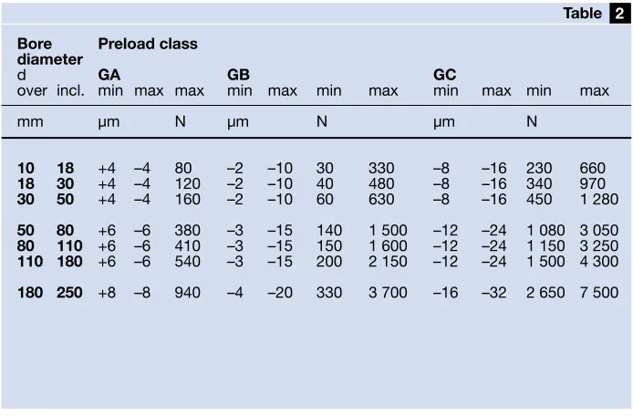
The values for the preload classes GA, GB and GC are given in table
and apply to bearing pairs in a back-to-back or face-to-face arrangement before mounting.
Speed ratings for bearing pairs
For bearings arranged in pairs, the ref-erence speeds provided in the product table for single bearings should be reduced by approximately 20 %.
Misalignment
Single row angular contact ball bear-ings have only limited ability to accommodate misalignment. The per-missible misalignment of the shaft rela-tive to the housing depends on the operating clearance in the bearing, bearing size, internal design and the forces and moments acting on the bearing. Because of the complex rela-tionship between the influencing fac-tors, it is not possible to quote any values which are universally valid. However, under normal operating con-ditions the value of the permissible misalignment for individual bearings lies between 2 and 6 minutes of arc. For bearings mounted in sets, par-ticularly those with small axial internal clearance when mounted in a back-to-back arrangement, angular misalign-ments can only be accommodated between the balls and raceways by force. This leads to increased ball loads and cage stresses as well as a reduction in bearing service life. Any misalignment of the bearing rings will also lead to an increase in running noise.
Cages
Depending on size and series, SKF single row angular contact ball bear-ings are equipped as standard with one of the cages described below. The available SKF standard assortment is
shown in tables and on pages
22and 23.
The standard cages used for single
4 3
2 1
• an injection moulded cage of glass fibre reinforced polyamide 6,6 (➔fig
), ball centred, designation suffix P, • a pressed window-type brass cage
(➔fig ), ball centred, designation suffix Y,
• a machined window-type brass cage
4 3
Axial internal clearance of sets of universally matchable bearings arranged back-to-back or face-to-face (before mounting and under zero measuring load)
Preload of bearing pairs consisting of universally matchable bearings arranged back-to-back or face-to-face (before mounting)
Bore Axial internal clearance diameter Class
d CA CB CC
over incl. min max min max min max
mm µm
10 18 5 13 15 23 24 32
18 30 7 15 18 26 32 40
30 50 9 17 22 30 40 48
50 80 11 23 26 38 48 60
80 110 14 26 32 44 55 67
110 180 17 29 35 47 62 74
180 250 21 37 45 61 74 90
1
Table
Bore Preload class diameter
d GA GB GC
over incl. min max max min max min max min max min max
mm µm N µm N µm N
10 18 +4 –4 80 –2 –10 30 330 –8 –16 230 660
18 30 +4 –4 120 –2 –10 40 480 –8 –16 340 970
30 50 +4 –4 160 –2 –10 60 630 –8 –16 450 1 280
50 80 +6 –6 380 –3 –15 140 1 500 –12 –24 1 080 3 050
80 110 +6 –6 410 –3 –15 150 1 600 –12 –24 1 150 3 250
110 180 +6 –6 540 –3 –15 200 2 150 –12 –24 1 500 4 300
180 250 +8 –8 940 –4 –20 330 3 700 –16 –32 2 650 7 500 2
Table
[image:20.595.203.550.55.276.2] [image:20.595.204.551.349.577.2]3
Page ... 3 Page ... 10 Single row bearings
Designation suffixes
The designation suffixes used to iden-tify certain features of SKF single row angular contact ball bearings are explained in the following.
A 30° contact angle
AC 25° contact angle
B 40° contact angle
CA Bearing for universal matching
mounted in random order; when arranged back-to-back or face-to-face the axial internal clear-ance will be smaller than Normal (CB)
CB Bearing for universal matching
mounted in random order; when arranged back-to-back or face-to-face the axial internal clear-ance will be Normal
CC Bearing for universal matching
mounted in random order; when arranged back-to-back or face-to-face the axial internal clear-ance will be greater than Normal (CB)
DB Two bearings matched
back-to-back
DF Two bearings matched
face-to-face
DT Two bearings matched in tandem
E Optimized internal design
F Machined steel cage
GA Bearing for universal matching
mounted in random order; when arranged back-to-back or face-to-face there will be a light preload
GB Bearing for universal matching
mounted in random order; when arranged back-to-back or face-to-face there will be a moderate preload
GC Bearing for universal matching
mounted in random order; when arranged back-to-back or face-to-face there will be a heavy preload
J Pressed steel cage, ball centred
M Machined brass cage, ball
centred, different designs are identified by a figure, e.g. M1
N1 One locating slot in the outer ring
N2 Two locating slots in the outer ring, positioned at 180° to each other
P Injection moulded cage of glass
fibre reinforced polyamide 6,6, ball centred
P5 Dimensional and running accuracy
to ISO tolerance class 5
P6 Dimensional and running accuracy
to ISO tolerance class 6
W64Solid Oil filling
Y Pressed window-type brass
cage, ball centred
Polyamide cage
Pressed brass cage
3
Fig
4
Fig
Note
Single row angular contact ball bearings with polyamide 6,6 cages can be used at tempera-tures up to +120 °C (250 °F). With the exception of a few oils and greases with a synthetic oil base, and lubricants containing a high proportion of EP additives when used at high temperatures, the lubricants generally used for rolling bearings do not have a detrimental effect on cage proper-ties.
Machined brass cage
5
Page ... 3 Page ... 10 Single row bearings
Assortment
SKF single row angular contact ball bearings in the 72 B and 73 B series are available in a number of variants. The standard assortment for bearings in the
• 72 B series is listed in table and • 73 B series is listed in table .
The dimensions and performance data of these bearings can be found in the product table starting on page 24.
Additional variants with other in-ternal clearance or preload values or different cage variations are available. For details, contact your local SKF representative.
Bearing designations
Tables and also contain the bearing designations of the bearings available in the standard assortment. The table headings show bearing des-ignations without the size code; a grey coloured square indicates the position for the size.
Example of an order designation
A universally matchable bearing in the 73 BE series
• with a 60 mm bore diameter (bearing size 12),
• with Normal axial internal clearance when arranged back-to-back or face-to-face as bearing pair (CB), • with a cage of glass fibre reinforced
polyamide 6,6 (P)
has 7312 BECBP as order designation. The meaning of relevant designation suffixes is explained on page 21.
When ordering universally match-able bearings it is necessary to state the number of individual bearings required – not the number of pairs.
4 3
4 3
Universally matchable bearings Basic design bearings
SKF Explorer bearing
3 Table 10 12 15 17 20 25 30 35 40 45 50 55 60 65 70 75 80 85 90 95 100 105 110 120 130 140 150 160 170 180 190 200 220 240 Bor e diameter
mm 72
Universally matchable bearings Basic design bearings
SKF Explorer bearing Other SKF standard bearing 10 12 15 17 20 25 30 35 40 45 50 55 60 65 70 75 80 85 90 95 100 105 110 120 130 140 150 160 170 180 190 200 220 240
3
Page ... 3 Page ... 10 Single row bearings
Bor e diameter mm 73 BECAP 73 BECBP 73 BEGAP 73 BEGBP 73 BECBY 73 BEGBY 73 B(E)CBM 73 BECCM 73 BEGAM 73 B(E)GBM 73 BEP 73 BEY 73 B(E)M Bearing size 4 Table
Page ... 3 Page ... 10 Single row angular contact ball bearings
d 10 – 35 mm
D D
B
d d
a r
r r
r r r
r r12 4 3
1 2 1
2
1 1
Principal Basic load ratings Fatigue Speed ratings Mass Designations* dimensions dynamic static load Reference Limiting Universally Basic
limit speed speed matchable design
d D B C C0 Pu bearing bearing
mm kN kN r/min kg –
10 30 9 7,02 3,35 0,14 30 000 30 000 0,030 7200 BECBP 7200 BEP
12 32 10 7,61 3,8 0,16 26 000 26 000 0,036 7201 BECBP 7201 BEP
37 12 10,6 5 0,208 24 000 24 000 0,063 – 7301 BEP
15 35 11 8,84 4,8 0,204 24 000 24 000 0,045 7202 BECBP 7202 BEP
42 13 13 6,7 0,28 20 000 20 000 0,081 7302 BECBP 7302 BEP
17 40 12 11 5,85 0,25 22 000 22 000 0,064 7203 BECBP –
40 12 10,4 5,5 0,236 20 000 20 000 0,064 – 7203 BEP
40 12 11,1 6,1 0,26 20 000 20 000 0,064 – 7203 BEY
40 12 11 5,85 0,25 22 000 22 000 0,070 7203 BECBM –
47 14 15,9 8,3 0,355 19 000 19 000 0,11 7303 BECBP 7303 BEP
20 47 14 14 8,3 0,355 18 000 18 000 0,11 7204 BECBP 7204 BEP
47 14 14 8,3 0,355 18 000 18 000 0,11 7204 BECBY –
47 14 13,3 7,65 0,325 18 000 19 000 0,11 7204 BECBM –
52 15 19 10 0,425 18 000 18 000 0,14 7304 BECBP –
52 15 17,4 9,5 0,4 16 000 16 000 0,14 – 7304 BEP
52 15 19 10,4 0,44 16 000 16 000 0,15 7304 BECBY 7304 BEY
52 15 19 10 0,425 18 000 18 000 0,15 7304 BECBM –
25 52 15 15,6 10 0,43 17 000 17 000 0,13 7205 BECBP –
52 15 14,8 9,3 0,4 15 000 15 000 0,13 – 7205 BEP
52 15 15,6 10,2 0,43 15 000 15 000 0,13 7205 BECBY 7205 BEY
52 15 15,6 10 0,43 17 000 17 000 0,14 7205 BECBM –
62 17 26,5 15,3 0,655 15 000 15 000 0,23 7305 BECBP –
62 17 24,2 14 0,6 14 000 14 000 0,23 – 7305 BEP
62 17 26 15,6 0,655 14 000 14 000 0,24 7305 BECBY 7305 BEY
62 17 26,5 15,3 0,655 15 000 15 000 0,24 7305 BECBM –
30 62 16 24 15,6 0,655 14 000 14 000 0,19 7206 BECBP –
62 16 22,5 14,3 0,61 13 000 13 000 0,19 – 7206 BEP
62 16 23,8 15,6 0,655 13 000 13 000 0,21 7206 BECBY 7206 BEY
62 16 24 15,6 0,655 14 000 14 000 0,21 7206 BECBM –
72 19 35,5 21,2 0,9 13 000 13 000 0,33 7306 BECBP –
72 19 32,5 19,3 0,815 12 000 12 000 0,33 – 7306 BEP
72 19 34,5 21,2 0,9 12 000 12 000 0,37 7306 BECBY 7306 BEY
72 19 35,5 21,2 0,9 13 000 13 000 0,37 7306 BECBM –
35 72 17 31 20,8 0,88 12 000 12 000 0,28 7207 BECBP –
72 17 29,1 19 0,815 11 000 11 000 0,28 – 7207 BEP
72 17 30,7 20,8 0,88 11 000 11 000 0,30 7207 BECBY 7207 BEY
72 17 31 20,8 0,88 12 000 12 000 0,30 7207 BECBM –
80 21 41,5 26,5 1,14 11 000 11 000 0,45 7307 BECBP –
80 21 39 24,5 1,04 10 000 10 000 0,45 – 7307 BEP
80 21 39 24,5 1,04 10 000 10 000 0,49 7307 BECBY 7307 BEY
3
Page ... 3 Page ... 10
da
Da
ra
ra
Db
Da
ra
rb
Dimensions Abutment and fillet dimensions
d d1 d2 D1 r1,2 r3,4 a da Da Db ra rb
∼ ∼ ∼ min min min max max max max
mm mm
10 18,3 14,6 22,9 0,6 0,3 13 14,2 25,8 27,6 0,6 0,3
12 20,2 16,6 25 0,6 0,3 14,4 16,2 27,8 29,6 0,6 0,3
21,8 17 28,3 1 0,6 16,3 17,6 31,4 32,8 1 0,6
15 22,7 19 27,8 0,6 0,3 16 19,2 30,8 32,6 0,6 0,3
26 20,7 32,6 1 0,6 18,6 20,6 36,4 37,8 1 0,6
17 26,3 21,7 31,2 0,6 0,6 18 21,2 35,8 35,8 0,6 0,6
26,3 21,7 31,2 0,6 0,6 18 21,2 35,8 35,8 0,6 0,6
26,3 21,7 31,2 0,6 0,6 18 21,2 35,8 35,8 0,6 0,6
26,3 21,7 31,2 0,6 0,6 18 21,2 35,8 35,8 0,6 0,6
28,7 22,8 36,2 1 0,6 20,4 22,6 41,4 42,8 1 0,6
20 30,8 25,9 37 1 0,6 21 25,6 41,4 42,8 1 0,6
30,8 25,9 37 1 0,6 21 25,6 41,4 42,8 1 0,6
30,8 25,9 37 1 0,6 21 25,6 41,4 42,8 1 0,6
33,3 26,8 40,4 1,1 0,6 22,8 27 45 47,8 1 0,6
33,3 26,8 40,4 1,1 0,6 22,8 27 45 47,8 1 0,6
33,3 26,8 40,4 1,1 0,6 22,8 27 45 47,8 1 0,6
33,3 26,8 40,4 1,1 0,6 22,8 27 45 47,8 1 0,6
25 36,1 30,9 41,5 1 0,6 23,7 30,6 46,4 47,8 1 0,6
36,1 30,9 41,5 1 0,6 23,7 30,6 46,4 47,8 1 0,6
36,1 30,9 41,5 1 0,6 23,7 30,6 46,4 47,8 1 0,6
36,1 30,9 41,5 1 0,6 23,7 30,6 46,4 47,8 1 0,6
39,8 32,4 48,1 1,1 0,6 26,8 32 55 57,8 1 0,6
39,8 32,4 48,1 1,1 0,6 26,8 32 55 57,8 1 0,6
39,8 32,4 48,1 1,1 0,6 26,8 32 55 57,8 1 0,6
39,8 32,4 48,1 1,1 0,6 26,8 32 55 57,8 1 0,6
30 42,7 36,1 50,1 1 0,6 27,3 35,6 56,4 57,8 1 0,6
42,7 36,1 50,1 1 0,6 27,3 35,6 56,4 57,8 1 0,6
42,7 36,1 50,1 1 0,6 27,3 35,6 56,4 57,8 1 0,6
42,7 36,1 50,1 1 0,6 27,3 35,6 56,4 57,8 1 0,6
46,6 37,9 56,5 1,1 0,6 31 37 65 67,8 1 0,6
46,6 37,9 56,5 1,1 0,6 31 37 65 67,8 1 0,6
46,6 37,9 56,5 1,1 0,6 31 37 65 67,8 1 0,6
46,6 37,9 56,5 1,1 0,6 31 37 65 67,8 1 0,6
35 49,7 42 58,3 1,1 0,6 31 42 65 67,8 1 0,6
49,7 42 58,3 1,1 0,6 31 42 65 67,8 1 0,6
49,7 42 58,3 1,1 0,6 31 42 65 67,8 1 0,6
49,7 42 58,3 1,1 0,6 31 42 65 67,8 1 0,6
52,8 43,6 63,3 1,5 1 35 44 71 74,4 1,5 1
52,8 43,6 63,3 1,5 1 35 44 71 74,4 1,5 1
52,8 43,6 63,3 1,5 1 35 44 71 74,4 1,5 1
52,8 43,6 63,3 1,5 1 35 44 71 74,4 1,5 1
Conversion factors: Length: 1 mm = 0,0394 in
1 in = 25,4 mm Force: 1 N = 0,225 lbf 1 lbf = 4,4482 N Mass: 1 kg = 2,205 lb
Page ... 3 Page ... 10 Single row angular contact ball bearings
d 40 – 60 mm
Principal Basic load ratings Fatigue Speed ratings Mass Designations* dimensions dynamic static load Reference Limiting Universally Basic
limit speed speed matchable design
d D B C C0 Pu bearing bearing
mm kN kN r/min kg –
40 80 18 36,5 26 1,1 11 000 11 000 0,37 7208 BECBP –
80 18 34,5 24 1,02 10 000 10 000 0,37 – 7208 BEP
80 18 36,4 26 1,1 10 000 10 000 0,38 7208 BECBY 7208 BEY
80 18 36,5 26 1,1 11 000 11 000 0,39 7208 BECBM –
80 18 34,5 24 1,02 10 000 10 000 0,39 – 7208 BEM
90 23 50 32,5 1,37 10 000 10 000 0,61 7308 BECBP –
90 23 46,2 30,5 1,13 9 000 9 000 0,61 – 7308 BEP
90 23 49,4 33,5 1,4 9 000 9 000 0,64 7308 BECBY 7308 BEY
90 23 50 32,5 1,37 10 000 10 000 0,68 7308 BECBM –
45 85 19 38 28,5 1,22 10 000 10 000 0,42 7209 BECBP –
85 19 35,8 26 1,12 9 000 9 000 0,42 – 7209 BEP
85 19 37,7 28 1,2 9 000 9 000 0,43 7209 BECBY 7209 BEY
85 19 38 28,5 1,22 10 000 10 000 0,44 7209 BECBM –
100 25 61 40,5 1,73 9 000 9 000 0,82 7309 BECBP –
100 25 55,9 37,5 1,73 8 000 8 000 0,82 – 7309 BEP
100 25 60,5 41,5 1,73 8 000 8 000 0,86 7309 BECBY 7309 BEY
100 25 61 40,5 1,73 9 000 9 000 0,90 7309 BECBM –
50 90 20 40 31 1,32 9 000 9 000 0,47 7210 BECBP –
90 20 37,7 28,5 1,22 8 500 8 500 0,47 – 7210 BEP
90 20 39 30,5 1,29 8 500 8 500 0,47 7210 BECBY 7210 BEY
90 20 40 31 1,32 9 000 9 000 0,51 7210 BECBM –
110 27 75 51 2,16 8 000 8 000 1,04 7310 BECBP –
110 27 68,9 47,5 2 7 500 7 500 1,04 – 7310 BEP
110 27 74,1 51 2,2 7 500 7 500 1,13 7310 BECBY 7310 BEY
110 27 75 51 2,16 8 000 8 000 1,16 7310 BECBM –
55 100 21 48,8 38 1,63 7 500 7 500 0,62 7211 BECBP 7211 BEP
100 21 48,8 38 1,63 7 500 7 500 0,62 7211 BECBY 7211 BEY
100 21 46,2 36 1,53 7 500 8 000 0,66 7211 BECBM –
120 29 85 60 2,55 7 000 7 000 1,34 7311 BECBP –
120 29 79,3 55 2,32 6 700 6 700 1,34 – 7311 BEP
120 29 85,2 60 2,55 6 700 6 700 1,48 7311 BECBY 7311 BEY
120 29 85 60 2,55 7 000 7 000 1,49 7311 BECBM –
60 110 22 61 50 2,12 7 500 7 500 0,78 7212 BECBP –
110 22 57,2 45,5 1,93 7 000 7 000 0,78 – 7212 BEP
110 22 57,2 45,5 1,93 7 000 7 000 0,83 7212 BECBY 7212 BEY
110 22 61 50 2,12 7 500 7 500 0,85 7212 BECBM –
130 31 104 76,5 3,2 6 700 6 700 1,71 7312 BECBP –
130 31 95,6 69,5 3 6 000 6 000 1,71 – 7312 BEP
130 31 95,6 69,5 3 6 000 6 000 1,75 7312 BECBY 7312 BEY
130 31 104 76,5 3,2 6 700 6 700 1,88 7312 BECBM –
130 31 95,6 69,5 3 6 000 6 300 1,88 – 7312 BEM
D D
B
d d
a r
r r
r r r
r r12 4 3
1 2 1
2
3
Page ... 3 Page ... 10
Conversion factors: Length: 1 mm = 0,0394 in
1 in = 25,4 mm Force: 1 N = 0,225 lbf 1 lbf = 4,4482 N Mass: 1 kg = 2,205 lb
1 lb = 0,454 kg
Dimensions Abutment and fillet dimensions
d d1 d2 D1 r1,2 r3,4 a da Da Db ra rb
∼ ∼ ∼ min min min max max max max
mm mm
40 56,3 48,1 65,6 1,1 0,6 34 47 73 75,8 1 0,6
56,3 48,1 65,6 1,1 0,6 34 47 73 75,8 1 0,6
56,3 48,1 65,6 1,1 0,6 34 47 73 75,8 1 0,6
56,3 48,1 65,6 1,1 0,6 34 47 73 75,8 1 0,6
56,3 48,1 65,6 1,1 0,6 34 47 73 75,8 1 0,6
59,7 49,6 71,6 1,5 1 39 49 81 84,4 1,5 1
59,7 49,6 71,6 1,5 1 39 49 81 84,4 1,5 1
59,7 49,6 71,6 1,5 1 39 49 81 84,4 1,5 1
59,7 49,6 71,6 1,5 1 39 49 81 84,4 1,5 1
45 60,9 52,7 70,2 1,1 0,6 37 52 78 80,8 1 0,6
60,9 52,7 70,2 1,1 0,6 37 52 78 80,8 1 0,6
60,9 52,7 70,2 1,1 0,6 37 52 78 80,8 1 0,6
60,9 52,7 70,2 1,1 0,6 37 52 78 80,8 1 0,6
66,5 55,3 79,8 1,5 1 43 54 91 94,4 1,5 1
66,5 55,3 79,8 1,5 1 43 54 91 94,4 1,5 1
66,5 55,3 79,8 1,5 1 43 54 91 94,4 1,5 1
66,5 55,3 79,8 1,5 1 43 54 91 94,4 1,5 1
50 65,8 57,7 75,2 1,1 0,6 39 57 83 85,8 1 0,6
65,8 57,7 75,2 1,1 0,6 39 57 83 85,8 1 0,6
65,8 57,7 75,2 1,1 0,6 39 57 83 85,8 1 0,6
65,8 57,7 75,2 1,1 0,6 39 57 83 85,8 1 0,6
73,8 61,1 88,8 2 1 47 61 99 104 2 1
73,8 61,1 88,8 2 1 47 61 99 104 2 1
73,8 61,1 88,8 2 1 47 61 99 104 2 1
73,8 61,1 88,8 2 1 47 61 99 104 2 1
55 72,4 63,6 83,7 1,5 1 43 64 91 94 1,5 1
72,4 63,6 83,7 1,5 1 43 64 91 94 1,5 1
72,4 63,6 83,7 1,5 1 43 64 91 94 1,5 1
80,3 66,7 96,6 2 1 51 66 109 114 2 1
80,3 66,7 96,6 2 1 51 66 109 114 2 1
80,3 66,7 96,6 2 1 51 66 109 114 2 1
80,3 66,7 96,6 2 1 51 66 109 114 2 1
60 79,6 69,3 91,55 1,5 1 47 69 101 104 1,5 1
79,6 69,3 91,6 1,5 1 47 69 101 104 1,5 1
79,6 69,3 91,6 1,5 1 47 69 101 104 1,5 1
79,6 69,3 91,6 1,5 1 47 69 101 104 1,5 1
87,3 72,6 104,8 2,1 1,1 55 72 118 123 2 1
87,3 72,6 104,8 2,1 1,1 55 72 118 123 2 1
87,3 72,6 104,8 2,1 1,1 55 72 118 123 2 1
87,3 72,6 104,8 2,1 1,1 55 72 118 123 2 1
87,3 72,6 104,8 2,1 1,1 55 72 118 123 2 1
da
Da
ra
ra
Db
Da
ra
Page ... 3 Page ... 10 Single row angular contact ball bearings
d 65 – 90 mm
Principal Basic load ratings Fatigue Speed ratings Mass Designations* dimensions dynamic static load Reference Limiting Universally Basic
limit speed speed matchable design
d D B C C0 Pu bearing bearing
mm kN kN r/min kg –
65 120 23 66,3 54 2,28 6 300 6 300 1,00 7213 BECBP 7213 BEP
120 23 66,3 54 2,28 6 300 6 300 1,00 7213 BECBY 7213 BEY
120 23 66,3 54 2,28 6 300 6 700 1,10 7213 BECBM –
140 33 116 86,5 3,65 6 300 6 300 2,10 7313 BECBP –
140 33 108 80 3,35 5 600 5 600 2,15 7313 BECBY 7313 BEP
140 33 116 86,5 3,65 6 300 6 300 2,31 7313 BECBM –
70 125 24 75 64 2,7 6 300 6 300 1,10 7214 BECBP –
125 24 71,5 60 2,5 6 000 6 000 1,10 7214 BECBY 7214 BEP
125 24 72 60 2,55 6 300 6 300 1,18 7214 BECBM –
150 35 127 98 3,9 5 600 5 600 2,55 7314 BECBP –
150 35 119 90 3,65 5 300 5 300 2,67 7314 BECBY 7314 BEP
150 35 127 98 3,9 5 600 5 600 2,83 7314 BECBM –
75 130 25 72,8 64 2,65 5 600 5 600 1,18 7215 BECBP 7215 BEP
130 25 72,8 64 2,65 5 600 5 600 1,26 7215 BECBY –
130 25 70,2 60 2,5 5 600 6 000 1,29 7215 BECBM –
160 37 132 104 4,15 5 300 5 300 3,06 7315 BECBP –
160 37 125 98 3,8 5 000 5 000 3,06 – 7315 BEP
160 37 133 106 4,15 5 000 5 000 3,20 7315 BECBY –
160 37 132 104 4,15 5 300 5 300 3,26 7315 BECBM –
80 140 26 80,6 69,5 2,8 5 300 5 300 1,43 7216 BECBP 7216 BEP
140 26 83,2 73,5 3 5 300 5 300 1,58 7216 BECBY –
140 26 85 75 3,05 5 600 5 600 1,59 7216 BECBM –
170 39 143 118 4,5 5 000 5 000 3,64 7316 BECBP –
170 39 135 110 4,15 4 500 4 500 3,64 – 7316 BEP
170 39 143 118 4,5 4 500 4 500 3,70 7316 BECBY 7316 BEY
170 39 143 118 4,5 5 000 5 000 4,03 7316 BECBM –
170 39 135 110 4,15 4 500 4 800 3,80 – 7316 BEM
85 150 28 95,6 83 3,25 5 000 5 000 1,83 7217 BECBP 7217 BEP
150 28 95,6 83 3,25 5 000 5 000 1,83 7217 BECBY –
150 28 95,6 83 3,25 5 000 5 300 1,99 7217 BECBM –
180 41 156 132 4,9 4 800 4 800 4,26 7317 BECBP –
180 41 146 112 4,5 4 300 4 300 4,26 – 7317 BEP
180 41 153 132 4,9 4 300 4 300 4,59 7317 BECBY –
180 41 156 132 4,9 4 800 4 800 4,74 7317 BECBM –
180 41 146 112 4,5 4 300 4 500 4,74 – 7317 BEM
90 160 30 108 96,5 3,65 4 500 4 500 2,12 7218 BECBP 7218 BEP
160 30 108 96,5 3,65 4 500 4 500 2,34 7218 BECBY –
160 30 108 96,5 3,65 4 500 4 800 2,41 7218 BECBM –
190 43 166 146 5,3 4 500 4 500 4,98 7318 BECBP –
190 43 156 134 4,8 4 000 4 000 4,98 – 7318 BEP
190 43 165 146 5,2 4 000 4 000 5,22 7318 BECBY –
190 43 166 146 5,3 4 500 4 500 5,53 7318 BECBM –
190 43 156 134 4,8 4 000 4 300 5,53 – 7318 BEM
D D
B
d d
a r
r r
r r r
r r12 4 3
1 2 1
2
3
Page ... 3 Page ... 10
Conversion factors: Length: 1 mm = 0,0394 in
1 in = 25,4 mm Force: 1 N = 0,225 lbf 1 lbf = 4,4482 N Mass: 1 kg = 2,205 lb
1 lb = 0,454 kg
Dimensions Abutment and fillet dimensions
d d1 d2 D1 r1,2 r3,4 a da Da Db ra rb
∼ ∼ ∼ min min min max max max max
mm mm
65 86,4 75,5 100 1,5 1 50 74 111 114 1,5 1
86,4 75,5 100 1,5 1 50 74 111 114 1,5 1
86,4 75,5 100 1,5 1 50 74 111 114 1,5 1
94,2 78,5 112,9 2,1 1,1 60 77 128 133 2 1
94,2 78,5 112,9 2,1 1,1 60 77 128 133 2 1
94,2 78,5 112,9 2,1 1,1 60 77 128 133 2 1
70 91,5 80,3 104,8 1,5 1 53 79 116 119 1,5 1
91,5 80,3 104,8 1,5 1 53 79 116 119 1,5 1
91,5 80,3 104,8 1,5 1 53 79 116 119 1,5 1
101,1 84,4 121 2,1 1,1 64 82 138 143 2 1
101,1 84,4 121 2,1 1,1 64 82 138 143 2 1
101,1 84,4 121 2,1 1,1 64 82 138 143 2 1
75 96,3 85,3 110,1 1,5 1 56 84 121 124 1,5 1
96,3 85,3 110,1 1,5 1 56 84 121 124 1,5 1
96,3 85,3 110,1 1,5 1 56 84 121 124 1,5 1
108,3 91,1 128,7 2,1 1,1 68 87 148 153 2 1
108,3 91,1 128,7 2,1 1,1 68 87 148 153 2 1
108,3 91,1 128,7 2,1 1,1 68 87 148 153 2 1
108,3 91,1 128,7 2,1 1,1 68 87 148 153 2 1
80 103,6 91,4 117,9 2 1 59 91 129 134 2 1
103,6 91,4 117,9 2 1 59 91 129 134 2 1
103,6 91,4 117,9 2 1 59 91 129 134 2 1
115,2 97,1 136,8 2,1 1,1 72 92 158 163 2 1
115,2 97,1 136,8 2,1 1,1 72 92 158 163 2 1
115,2 97,1 136,8 2,1 1,1 72 92 158 163 2 1
115,2 97,1 136,8 2,1 1,1 72 92 158 163 2 1
115,2 97,1 136,8 2,1 1,1 72 92 158 163 2 1
85 110,1 97 126,7 2 1 63 96 139 144 2 1
110,1 97 126,7 2 1 63 96 139 144 2 1
110,1 97 126,7 2 1 63 96 139 144 2 1
122,3 103 145 3 1,1 76 99 166 173 2,5 1
122,3 103 145 3 1,1 76 99 166 173 2,5 1
122,3 103 145 3 1,1 76 99 166 173 2,5 1
122,3 103 145 3 1,1 76 99 166 173 2,5 1
122,3 103 145 3 1,1 76 99 166 173 2,5 1
90 117,1 103 134,8 2 1 67 101 149 154 2 1
117,1 103 134,8 2 1 67 101 149 154 2 1
117,1 103 134,8 2 1 67 101 149 154 2 1
129,2 109 153,1 3 1,1 80 104 176 183 2,5 1
129,2 109 153,1 3 1,1 80 104 176 183 2,5 1
129,2 109 153,1 3 1,1 80 104 176 183 2,5 1
129,2 109 153,1 3 1,1 80 104 176 183 2,5 1
129,2 109 153,1 3 1,1 80 104 176 183 2,5 1
da
Da
ra
ra
Db
Da
ra
Page ... 3 Page ... 10 Single row angular contact ball bearings
d 95 – 170 mm
Principal Basic load ratings Fatigue Speed ratings Mass Designations* dimensions dynamic static load Reference Limiting Universally Basic
limit speed speed matchable design
d D B C C0 Pu bearing bearing
mm kN kN r/min kg –
95 170 32 124 108 4 4 300 4 300 2,68 7219 BECBP 7219 BEP
170 32 124 108 4 4 300 4 300 2,82 7219 BECBY –
170 32 129 118 4,4 4 800 4 800 2,95 7219 BECBM –
200 45 180 163 5,7 4 300 4 300 5,77 7319 BECBP –
200 45 168 150 5,2 3 800 3 800 5,77 – 7319 BEP
200 45 178 163 5,6 3 800 3 800 6,17 7319 BECBY –
200 45 180 163 5,7 4 300 4 300 6,41 7319 BECBM –
200 45 168 150 5,2 3 800 4 000 6,41 – 7319 BEM
100 180 34 135 122 4,4 4 000 4 000 3,29 7220 BECBP 7220 BEP
180 34 135 122 4,4 4 000 4 000 3,38 7220 BECBY 7220 BEY
180 34 135 122 4,4 4 000 4 300 3,61 7220 BECBM –
215 47 216 208 6,95 4 000 4 000 7,17 7320 BECBP –
215 47 203 190 6,4 3 600 3 600 7,17 – 7320 BEP
215 47 203 190 6,4 3 600 3 600 7,15 7320 BECBY 7320 BEY
215 47 216 208 6,95 4 000 4 000 8,00 7320 BECBM –
215 47 203 190 6,4 3 600 3 800 8,00 – 7320 BEM
105 190 36 148 137 4,8 3 800 3 800 3,82 7221 BECBP 7221 BEP
190 36 148 137 4,8 3 800 4 000 4,18 7221 BECBM –
225 49 212 208 6,95 3 400 3 400 8,46 7321 BECBP 7321 BEP
225 49 203 193 6,4 3 400 3 600 9,12 7321 BECBM –
110 200 38 163 153 5,2 3 600 3 600 4,60 7222 BECBP 7222 BEP
200 38 163 153 5,2 3 600 3 600 4,75 7222 BECBY –
200 38 153 143 4,9 3 600 3 800 4,95 7222 BECBM 7222 BEM
240 50 225 224 7,2 3 200 3 200 9,69 7322 BECBP 7322 BEP
240 50 225 224 7,2 3 200 3 200 9,69 7322 BECBY 7322 BEY
240 50 225 224 7,2 3 200 3 400 10,7 7322 BECBM 7322 BEM
120 215 40 165 163 5,3 3 400 3 600 5,89 7224 BCBM 7224 BM
260 55 238 250 7,65 3 000 3 200 13,8 7324 BCBM –
130 230 40 186 193 6,1 3 200 3 400 6,76 7226 BCBM 7226 BM
280 58 296 305 9 2 800 2 800 17,1 7326 BCBM 7326 BM
140 250 42 199 212 6,4 2 800 3 000 8,63 7228 BCBM 7228 BM
300 62 302 345 9,8 2 600 2 600 21,3 7328 BCBM –
150 270 45 216 240 6,95 2 600 2 800 10,8 7230 BCBM –
320 65 332 390 10,8 2 400 2 400 25,0 7330 BCBM –
160 290 48 255 300 8,5 2 400 2 600 13,6 7232 BCBM –
170 310 52 281 345 9,5 2 400 2 400 16,7 7234 BCBM –
360 72 390 490 12,7 2 000 2 200 34,6 7334 B