BACKGROUND
Angiogenenesis
Vascular Development and Quiescence
Arterial/venous specification is an important step in the maturation of the vascular system and has implications for angiogenesis. Anatomical and physiological features of the vascular system vary depending on position along the vascular tree21.
Physiological Angiogenesis
The behavior of the vascular endothelium is adapted to its position along the vascular tree. The extracellular matrix contains angiogenic signaling molecules that are released when MMPs degrade areas of the extracellular matrix.
Angiogenesis in Disease
Angiogenesis Assays
Types and Applications of Angiogenesis Assays
Three-dimensional Boyden chamber migration assays include non-endothelial cell types on the opposite side of the filter. Genetic engineering in mice allows the investigation of molecular mechanisms of angiogenesis using the corneal angiogenesis assay.
Aortic Ring Assay and Other Organ Explant Angiogenesis Assays
Limitations of organ explant testing in angiogenesis research include the use of vascular explants that poorly represent the microvasculature (where angiogenesis occurs), the difficulty of quantification, and the variability in results. As discussed above, quantification of angiogenesis in organ explant assays is difficult and prone to error. In mice, for example, age and genetic background strongly influence the results of the organ explant test99.
Mechanical Stimulation in Angiogenesis Assays
In vitro perfusion of the matrix materials mimics Darcy's law or Starling flow in the interstitium. Spatial-temporal control of the mechanical stimuli is complicated by changes that the matrix undergoes as a result of angiogenesis. Fluid shear stress can be added to a study of the interaction between multiple cell and extracellular matrix types.
Summary and Aims
METHODS
Mouse Aortic Ring Assay
- Equipment List
- Materials
- Euthanasia
- Explanting the Aorta
- Culturing the Aortic Ring Assay
- Data Acquisition
Another 20 µL layer of Matrigel was pipetted into the wells on top of the slices of aorta and allowed to harden. Vertical incisions were made in the abdominal muscle using one of the two microdissection scissors. This dish was placed under the objective of the dissection area and the aorta was placed inside the 1x PBS drop.
Whole Aorta Angiogenesis Assays in Cell Culture Dish
- Equipment
- Materials
- Explanting the Aorta
- Culturing the Aortic Ring Assay
- Data Acquisition
One aortic segment was placed on top of the Matrigel and centered within a well on the 96-well plate, and 20 µL of Matrigel was pipetted into the wells on top of the aortic slices. The mouse euthanasia and the aortic explantation in the Whole Aorta Angiogenesis Assay were performed as in the Mouse Aorta Ring Assay (Sections C.1.3 and C.1.4). After explantation, the aorta was sometimes catheterized as described in PVEB Mouse Aorta Assay (Section C.3.5).
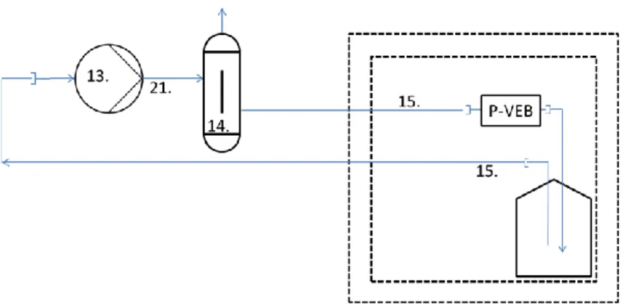
Perfused Vascular Explant Bioreactor (PVEB) Assay
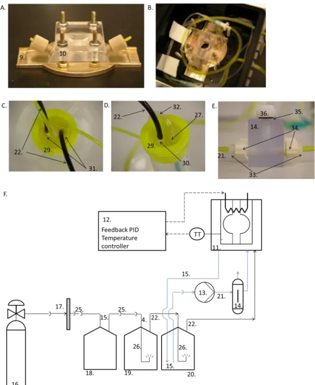
Equipment
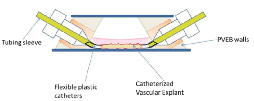
Commercial couplings (1) were attached with epoxy to the polycarbonate walls (2) of the bioreactor. The walls with openings were inclined inward by 60° relative to the reactor floor. Two approaches were used in incubation and perfusion of mouse aorta in PVEB.

Materials
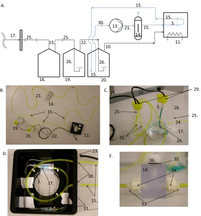
At least 4 h before use, the perfusion circuit was disconnected from the sterile filter and sterilized with ethanol (Section C.3.1.4). The perfusion circuit includes all equipment and tubing that transports CO2/air and sterilized media to the miniature incubator and PVEB. The distribution path of CO2 and moist air in the perfusion circuit is not a closed loop.
Initiating the Temperature Controller and Perfusion Loop
Alternate Assembly of Perfusion and Incubation Equipment
The sterile filter (17) is only connected after sterilization of the rest of the perfusion circuit. The CO2 supply line connected to the sterile filter was filled with 70% (v/v) ethanol in water, followed by DI water and then 1x PBS.
Explanting the Aorta
Catheterizing the Aorta
This placed the aorta toward the top of the reactor (away from the microscope objective). Areas of the aorta (severed arteries and angiogenic growths) did not fluoresce with the catheter. Areas of angiogenic outgrowth (B to H) were similar to those in the no-flow PVEB mouse aorta assay.
To identify functional nascent vessels in the mouse aortic PVEB assay, fluorescent microspheres were loaded into the lumen of the aorta. Angiogenesis in PVEB occurred at the sides of the aorta and from transected arborizing arteries.
Loading the Aorta into the PVEB
Culturing the Aortic Ring Assay
Data Acquisition
The red tint of the microsphere solution did not extend beyond the twist in the aorta. In the upper row, there is a small puncture or tear in the elastic lamina (tunica media) of the aorta. In the half of the hollow fiber near the exit, the abdominal space is slightly more pressurized.
Variability in the rate and extent of angiogenesis is a documented limitation of the vascular explant test. This suggests that the physiologically relevant features of the aortic ring test were retained in the PVEB.
Small Molecule and Particle Perfusion Experiments
Hollow Fiber Dye Rinsing Experiment
Mouse Aorta Fluorescent Microspheres Perfusion Experiments
The fluorescent microsphere perfusion experiment with mouse aorta used the same equipment as in the PVEB mouse aortic test (section C. 3.1). The Aortic Fluorescent Microspheres Perfusion Experiment in mice used the same materials as in the Aortic Ring Assay in mice (section C.1.2). A sterile 5% w/w stock solution of fluorescent microspheres in DI water was purchased months before use and stored at 4°C in the absence of light.
COMSOL Model of Small Molecule Diffusion and Convection in the PVEB
- Assumptions
- Geometry
- Equations
- Numerical Methods
The walls of the reactor are insulating (ie, the component of the velocity normal to the walls is zero). The Navier-Stokes region was re-solved using the fluid velocity along the edge of the hollow fiber (calculated with Darcy's law). Solving for the fluid velocity is used in the convective term of the solution mass transfer equation (5).
Hydraulic Impedance Measurements of a Perfused Aorta In Vitro
Equipment
The fluid flow solution for the Navier-Stokes region was calculated for an impermeable pipe.
Culturing the Aorta and Measuring its Impedance to Fluid Flow
Data Acquisition
- RESULTS
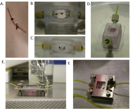
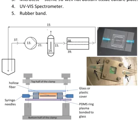
C.6, featured a slit in the PDMS ring, which allowed catheterization of the aorta (in situ or ex vivo) before loading it into the reactor. The model depicted non-zero tangential fluid velocity in the abluminal space along the wall of the hollow fiber. The pressure difference along the length of the hollow fiber was 2.3 Pa in the PVEB with one hollow fiber.
Angiogenesis in PVEB with flow appeared to favor the severed arborizing arteries (B to E), although angiogenesis also occurred along the sides of the aorta. Dark dots present in the hematoxylin and eosin stains of the aorta indicated the presence of intact nuclei (a marker of living cells).

Mouse Aortic Assay
Evolution of the Perfused Vascular Explant Bioreactor
The first design of the PVEB (PVEB1) featured a 2.5 cm square PDMS ring plasma bonded to glass. Plastic gel loading tips pushed through the walls of the PVEB served as perfusion connectors for the aorta. Here we modified aortic catheterization using shielded cannulas to fit commercial ferrule fittings.
Whole Aorta Angiogenesis Assay
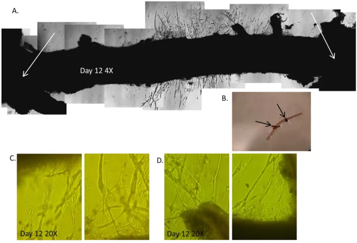
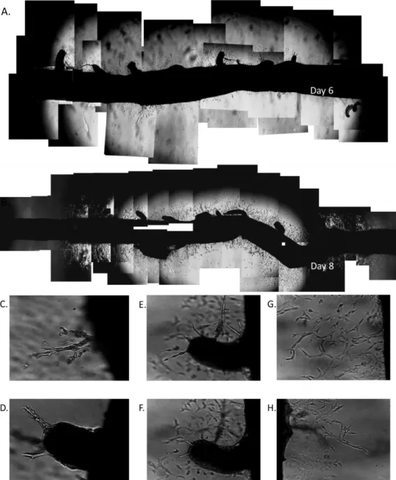
In the aortic ring assays, angiogenic outgrowth favored the tips of the aortic disc, although angiogenesis also occurred on severed arterials and along the sides of the aortic disc. Angiogenic outgrowth extended from the aorta, except near the knots in the Ethicon suture, indicated by arrows in (A) and (B). The outgrowth consisted of densely vascularized, more or less continuous tubular networks similar to those observed in the mouse aortic ring test (Fig. D.1).
Perfused Vascular Explant Bioreactor
Perfused Vascular Explant Bioreactor Mouse Aorta Assay without Flow
Small Molecule Perfusion Experiments
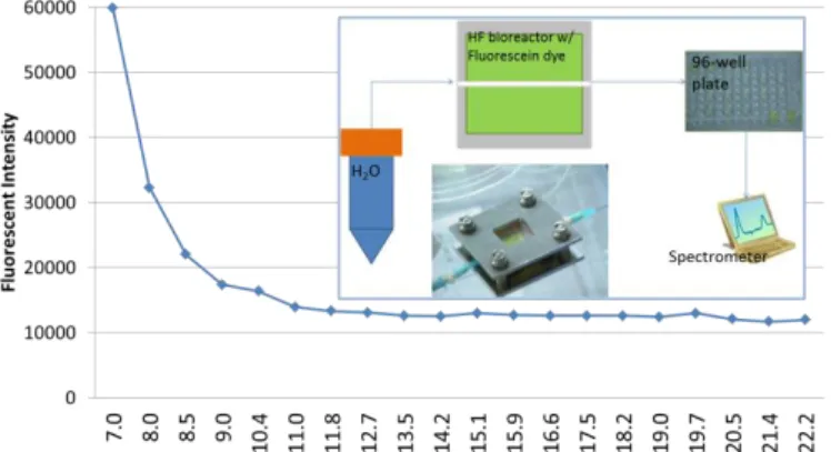
Hollow Fiber Dye Rinse Out
This estimate of solute permeability was used in the COMSOL model of small molecule transport in the PVEB. The networks of tubes sprouting from C) sides and D) cut arteries were morphologically similar to those in the aorta (Fig. D.1) and (Fig. D.2) whole aorta angiogenesis assays. The angiogenic growth contained regions whose morphology differed from that observed in the angiogenesis assays of rat aorta and whole aorta (G and H).
COMSOL Model of Small Molecule Transport in the PVEB
Perfusion of the Aorta with Microspheres
Microspheres were gently injected into the right side of the aorta, and the red hue of the microsphere solution reached the twist in the aorta but did not go any further.
Impedance Measurement
The model depicted a nonzero tangential fluid velocity in the abluminal space along the hollow fiber wall. Two countercurrent PVEB2 hollow fibers created a dead zone (i.e., no fluid flow) in the center of the abluminal space of the reactor. Two characteristic curves of the time dependence of impedance on fluid flow given by the aorta.
Angiogenic Outgrowth from a Perfused Mouse Aorta
DISCUSSION
Interpretation of Results
Long-Term Viable Culture of Perfused or Perfusable Aorta In Vitro
Haematoxylin and eosin stains of the elastic lamina in the aorta have layers of wavy, ribbon-like structures that stain pink124. I suspect that this resting contractile force in the smooth muscle causes it to contract the elastic lamina into bundles or ribbon-like structures. The elastic lamina of aortas cultured in the presence of perfusion appeared less ribbon-like than that of aortas cultured in the absence of perfusion.
Angiogenic Outgrowth from a Perfused or Perfusable Aorta In Vitro
The fluorescence in the abluminal space was not as bright as that in the aorta and in the angiogenic outgrowth. Although variable, the extent of angiogenesis (at day 6 in culture) tended to be greater with the aortic ring test than with the PVEB. Catheterization blocks the major escape route for endothelial cells in the aortic ring test (i.e. the tips).
Actuation and Measurement of the Mechanical Stimuli in the PVEB
In the mathematical model of small molecule diffusive mass transport in the PVEB, the hollow fiber was chosen as the model of the vascular explant. Mass transport of fluid flow in the abluminal space in the PVEB (with the aorta) is affected by spatial and temporal variations in the permeability of the Matrigel. An obvious next step in the development and implementation of the PVEB is to better characterize and quantify angiogenesis in the PVEB.
Solute and Particulate Transport in the PVEB
Significance
This improvement of the conventional vascular explantation assay expands the capabilities of the current armamentarium of angiogenesis assays. The angiogenesis in the PVEB produces vasculature that is morphologically identical to that in the vascular explant assay. In vitro qualities of the vascular explantation assay (eg, time-lapse imaging, precise control and measurement of angiogenic stimuli, absence of confounding inflammatory responses) are maintained in the PVEB.
Future Directions
Ohno, M., et al., “Fluid shear stress induces transcription and production of endothelial transforming growth factor beta-1” Journal of Clinical Investigation. Albini, A., et al., “Angiogenesis induced by HIV-1 Tat protein is mediated by the Flk-1/KDR. Resnick, N., et al., “Fluid shear stress and the vascular endothelium: for better and for worse.”
Schematic of the Perfused Vascular Explant Bioreactor (PVEB)
Schematics and Pictures of the PVEB
Schematics and Pictures of the Supporting Perfusion Tubing
Schematic of the Alternate Assembly of the PVEB and Perfusion Tubing
Perfusion Circuit Sterilization
Catheterizing the Aorta and Loading it into the PVEB
Hollow Fiber Dye Rinse Out
Demonstrative Aortic Ring Assay
Whole Aorta Angiogenesis Assay
Angiogenesis in the PVEB without Flow
H&E Stains of an Aorta Cultured in the PVEB without Intraluminal perfusion
H&E Stains of an Aorta Cultured in the PVEB with Intraluminal perfusion
Plot of Fluorescent Intensity of the Eluent from the Hollow Fiber Dye Rinse Out Experiment 66
Fluorescent Images of Aortas Loaded with Fluorescent Microspheres
Plot of Hydraulic Impedance of the Aorta vs. Time
Angiogenic Outgrowth from a Perfused Aorta In Vitro
Organs Used in the Vascular Explant Angiogenesis Assay
Parts List