I hereby declare that the present work presented in the thesis entitled "Seismic Response Control of Integral Abutment Bridge using Sleeved Piles" in partial fulfillment of the requirement for the award of the degree of Doctor of Philosophy is an authentic record of my own work done out in the Department of Civil Engineering at the Indian Institute of Technology (IIT) Guwahati. This thesis is the result of research conducted in the Department of Civil Engineering at the Indian Institute of Technology (IIT) Guwahati.
Abstract
For precise evaluation of seismic response of the bridge, the far field ground response is also incorporated in the modeling of the pile ground interaction. The seismic vulnerability of the IAB with and without sleeve pile is compared by developing an analytical fragility curve.
List of Tables
153 Table 5.1 Characteristics of first modes of model 1 and model 2 168 Table 5.2 Seismic moment vs length of sleeve pile in Model-1 and. 206 Table 6.4 Limit state definition for pier (Stefanidou and Kappos Table 6.5 Damage state for the bridge pier considered in this study 209 Table 6.6 Demand interpolated for IAB with and without sleeve pile.

Notations
𝐿 = length of column from critical point to the point of contraflexion 𝐿 = effective length of pile in which the frictional forces of the pile are effective. 𝐿 = Length of deformation penetration 𝐿 = length of pile above ground level 𝑙 = freestanding length of sleeve pile 𝑙 = effective length of sleeve pile.
Introduction
- Background
- Types of Integral Abutment Bridge
- Full Integral Abutment Bridge
- Semi-Integral Bridge
- Deck Extension
- Merits of Integral Abutment Bridge
- Problem Identification
- Objective of Present Study
- Scope of Study
- Outline of Thesis
This has led to wide acceptance of the Integral Abutment Bridge or Jointless Bridge. The numerical study of the feasibility of sleeved pile in seismic response control of the bridge is also carried out.

Literature Review
Introduction
In addition, it is very important to take into account the soil structure interaction in the analysis and design of the IAB, since all the deformation induced by external loading is transferred to the soil due to the integral connection of deck with abutment and pier. Therefore, a detailed study of the soil-structure interaction modeling strategies for IAB is carried out in a separate Chapter 3.
Foundation in Integral Abutment Bridge
Soil pile interaction and abutment fill interaction significantly affect the bridge response under the action of seismic excitation and thermal load. To reduce the influence of translation and rotation of the support, sleeves around the pile have also been adopted in England, Ireland and Sweden to avoid the inhibiting effect of the soil.
Finite Element Modelling and Seismic Analysis of IAB
Therefore, the second mode was observed to be the most important contributor to the seismic response of the bridge. These parametric studies clearly showed that the effect of setback on the seismic behavior of the bridge.
Maximum Length of IAB in Practice
Various transportation departments issued guidelines for the design and construction of IAB and prescribed the maximum length for different bridge types. The recommendation of a maximum allowable length of IAB without considering the oblique angle is shown in Table 2.1 (Dicleli and Albhaisi, 2003, White et al. 2005, Stoothoft and Conboy, 2005, Weakley, 2005).
Sleeved Pile for Foundation of Structures
Kaynia and Kausel (1980) developed expression for the dynamic stiffness of sleeve pile for seismic analysis of the sleeve pile in linear viscoelastic soil medium. When constructing the sleeve pile, the gap between the pile shaft is filled with compressible material.
Incremental Dynamic Analysis
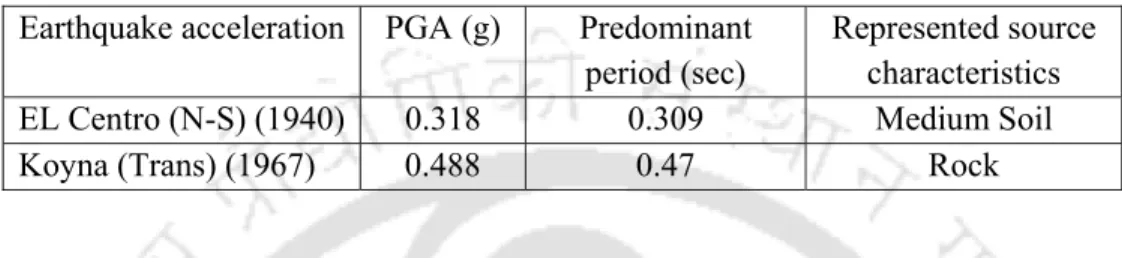
- Selection of Ground Motion
- Definition of Damage States
Multi-records is an IDA collection with a record of the same structural model under different accelerators. These corresponding qualitative damage states can be described by qualitative damage states in the form of component displacement.
Fragility function and Development of Fragility Curve of Bridge
The fragility curve of each bridge component was developed assuming that the bridge component demand and capacity are log-normally distributed. A fragility curve was developed for each component monitored in the analysis, assuming that the seismic demand and capacity of the component are log-normally distributed.
Concluding Remarks
In the case of the analysis of a single bridge, it was suggested to evaluate the nonlinear response history using the time history array. However, in the case of a single bridge, component fragility curves were developed from the IDA results.
Soil Structure Interactions Modelling Approach for Integral Abutment Bridge
Introduction
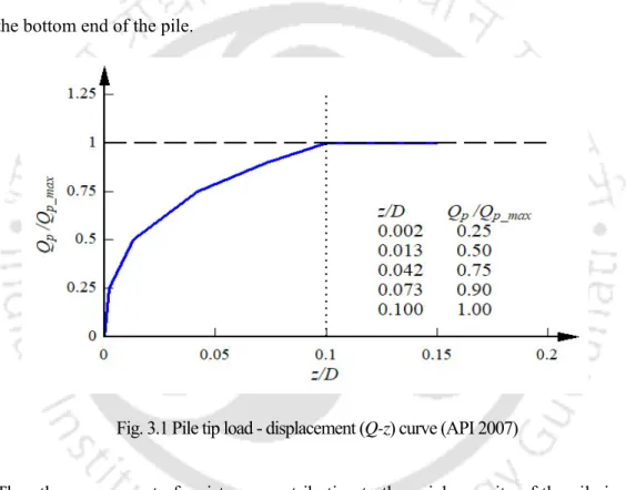
The interaction modeling of soil structure in the IAB includes modeling interactions with soil foundations and fill interactions with abutments. The generally accepted methods in modeling soil pile interaction, such as load settlement curve (𝑄 𝑧 curve for modeling the relationship between mobilized point bearing force and settlement), load transfer curve (𝑡 𝑧) for modeling the relationship between the mobilized friction forces of the shaft skin and the relative This study considers the motion of pile and soil and the load-displacement curve (𝑝 𝑦) to model the relationship between the lateral resistance of soil and pile displacement.
Soil Pile Interaction in Axially Loaded pile in Sand
The calculation of the maximum mobilized shaft friction force (𝑡) at different depths along the pile is calculated using the following equations (FEMA 356, 2000). The relationship between the motion of the pile and the mobilized shaft friction force proposed by Vijayvergiya (1977) is as.
Soil Pile Interaction in Axially loaded pile in Clay
In calculating the friction force, the top of the pile for an embedded length equal to four times the pile diameter is ignored as recommended by FEMA 356 (2000). The pile axial movement versus the skin friction force of the mobilized shaft is modeled by adopting the 𝑡 𝑧 curve as recommended by API (2007).
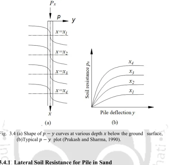
Soil Pile Interaction in Laterally Loaded Piles
- Lateral Soil Resistance for Pile in Sand
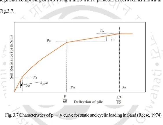
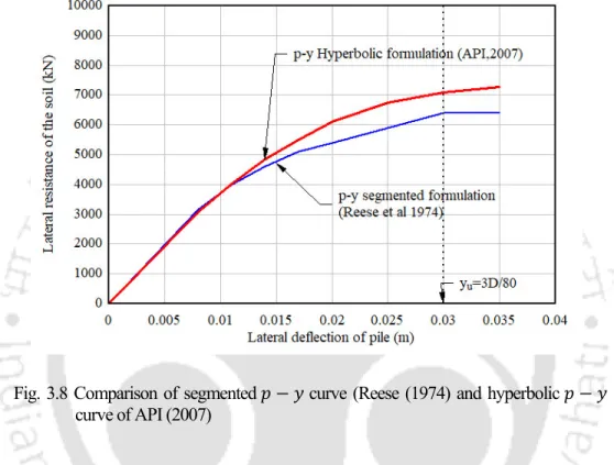
- Formulation of 𝒑 𝒚 Curve for Sand
- Lateral Load Resistance for Piles in Soft Clay
- Formulation of 𝒑 𝒚 for Soft Clay
- Lateral Load Resistance for Piles in Stiff Clay
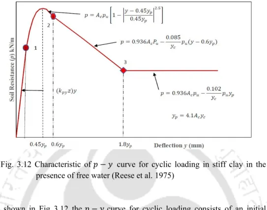
- Formulation of 𝒑 𝒚 curve for stiff Clay
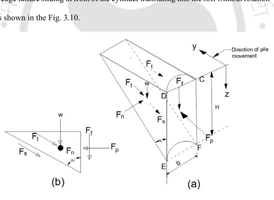
The total ultimate lateral resistance 𝐹 of the pile is equal to the passive force 𝐹 minus the active force 𝐹. The value of the final lateral resistance of the sand is calculated from the equations (3.12 and (3.15) proposed by Reese (1962).
Group Effect on 𝒑 𝒚 Curve
The group effect in the 𝑝 𝑦 curve is accounted for by adopting a p-multiplier that modifies the lateral soil resistance at different depths to take the group effect into the model. Furthermore, the elastic continuum could also not be responsible for the compaction of soil mass caused by piling process around the piles in the group.
Calculation of Linear Stiffness of Soil
Modelling of Far Field Soil Effect
𝜎 𝜎 is the asymptotic value of the stress difference which is related to the soil strength. The shear modulus of the soil at different pile depths was calculated using the relation as.

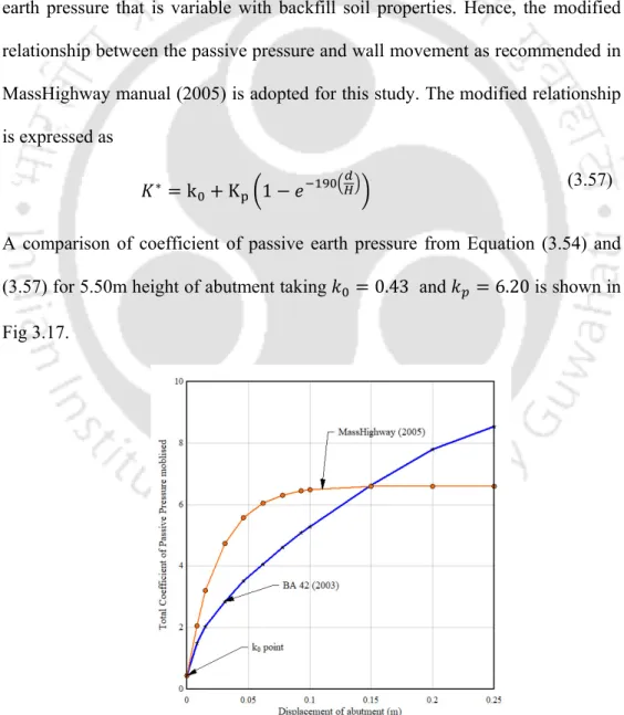
Abutment Backfill Interaction
Therefore, a modified relationship between passive pressure and wall motion as recommended in the MassHighway (2005) manual is adopted for this study. Thus, the recommendation of the MassHighway manual (2005) is followed, which gives a reasonable prediction of the passive pressure coefficient.
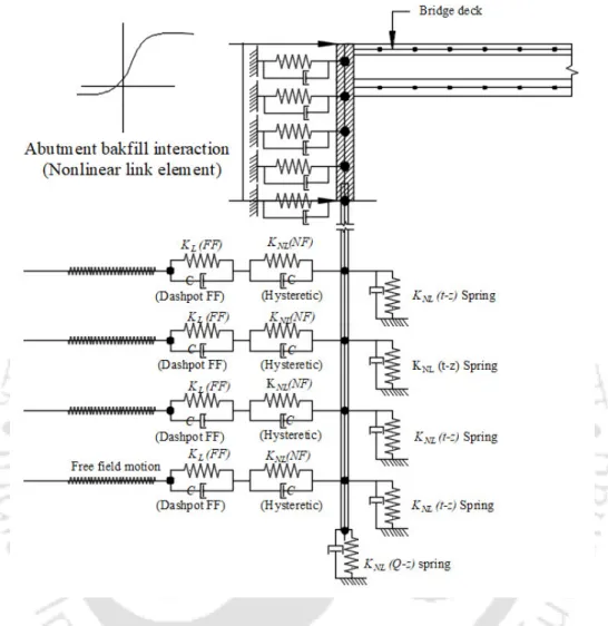
Implementation of Soil Pile Interaction
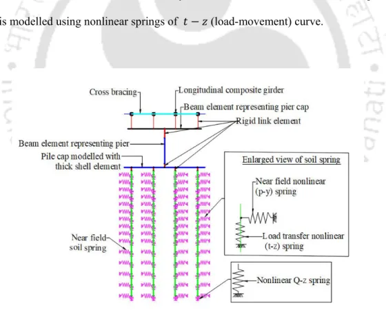
A schematic diagram of the process of modeling the pile under lateral and vertical without the inclusion of the soil element in the far field is shown in Fig. The ground contribution in the far field is modeled by a linear spring 𝐾 representing the linear response of the ground.
Concluding Remarks
In modeling the axial tip bearing interaction for piles in sand, clay and stiff clay, the load-settlement curve 𝑄 𝑧 recommended by API (2007) is found to be adequate. In the case of soft and stiff clay, the load transfer curve 𝑡 𝑧 recommended by API (2007) is appropriate.
Finite Element Modelling and Analysis of Integral Abutment Bridge
Introduction
Response spectrum analyzes of the bridge models with different soil types in the foundation are carried out to record the bridge's vibration characteristics and their comparison. Nonlinear time-history analyzes of the bridge are also performed to identify the effect of foundation soil properties on the seismic response of the bridge and to understand the effect of incorporating far-field ground response in soil-pile interaction modeling.
Description of the Bridge
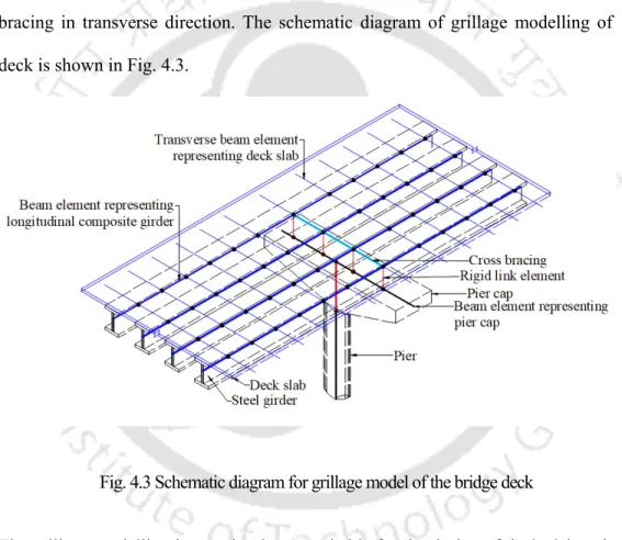
Finite Element Modelling of Bridge
As shown in the schematic diagram for strategies in finite element modeling of the bridge with pile foundation in Fig. The implementation of modeling of the plastic hinge is carried out by the moment curvature capacity points shown in Fig.
Modelling of Nonlinear Soil Pile Interactions
- Modelling of Soil Pile Interaction of Axially Loaded Pile in Sand
- Modelling of Soil Pile Interaction of Axially Loaded Pile in Clay
- Modelling of Soil Pile Interaction of Laterally Loaded Pile in Sand
- Modelling of Soil Pile Interaction of Laterally Loaded Pile in clay
The calculated 𝑄 𝑧 curve adopted when modeling the soil pile interaction for piles in soft and stiff clay is shown in Figure. The representative 𝑝 𝑦 curves for soft clay adopted when modeling the soil-pile interaction of a bridge in clay are shown in Fig.
![Table 4.2 Properties of different types soil [Tarzaghi et. al (1996)]](https://thumb-ap.123doks.com/thumbv2/azpdfnet/10545178.0/139.918.177.740.351.884/table-properties-different-types-soil-tarzaghi-et-1996.webp)
Modelling of Far Field Soil Reaction
The parameters such as modulus number, modulus exponent and failure ratio adopted in the calculation of the tangent modulus of elasticity of soil are taken from the values given by Duncan et al. The change of the representative values of the modulus of elasticity of the soil along the depth of the pile foundation, calculated using the equation (3.51) and adopted in the modeling of the stiffness of the pile is shown in Fig.
Modelling of Abutment Backfill Interaction
The earth pressure coefficient at rest, 𝑘, is set to 1.0, based on the Clough and Duncan (1991) recommendation for compacted backfill. The calculated non-linear abutment fill interaction curve has been adopted into the modeling and some representative curves at a depth of 3.0 m and at 4.75 m from the top of the abutment are as shown in Figure 4.20.
Effect of Different Lateral Soil-Structure Interaction Modelling Approach on Dynamic Characteristics of
As observed from Table 4.12, the participating mass ratio of first mode of NF model of the IAB in the longitudinal direction is almost zero. Thus, despite an increase in the participating mass ratio of the first mode of NF+FF model, there is a simultaneous decrease in the acceleration to the bridge.
Seismic Analysis of Integral Abutment bridge
Fig.4.44 Reaction history at the top of the bridge pier of the NF and NF+FF model in loose sand under Koyna ground motion excitation. Fig.4.47 Reaction history at the top of the bridge pillar of the NF and NF+FF model in soft clay under Koyna ground motion excitation.
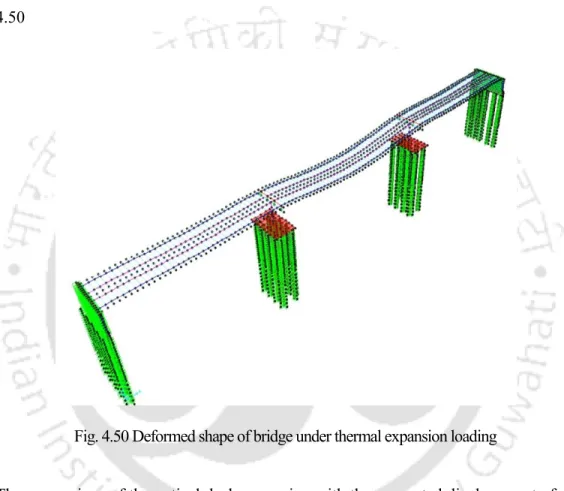
Thermal Load Analysis
4.51 (a) shows the displacement of the abutment together with the pile supporting abutment under thermal expansion due to variation of temperature by 17.50 C. The degree of deflection of the pier pile is observed to be too small to cause significant stress in the pile .
Concluding Remarks
The thermal moment induced in the pile and abutment is much below the elastic moment capacity of the abutment wall and pile. In the IAB with current configuration of abutment supported with concrete pile, the displacement of the abutment wall under the thermal load is observed primarily in the form of rotation of the abutment around its base.
Structural Response Control of Integral Abutment Bridge using Sleeved Pile
Introduction
Based on the results of parametric studies on the dynamic properties of IAB with sleeve pile, a design methodology is proposed for sleeve pile foundation of the bridge. The response of IAB with sleeve pile subjected to thermal loading is also studied for observing the beneficial effect of sleeve pile in the overall performance of the bridge under thermal load.
Structural Arrangement of Sleeved Pile Foundation
In this chapter, the introduction of sleeved piles is explored with the aim of improving the performance of the bridge under seismic excitation. The load transfer from the steel pile to the casing and back to the ground takes place in the part of the steel pile embedded in the concrete.