Electric, and Fuel Cell Vehicles
Third Edition
Electric, and Fuel Cell Vehicles
Third Edition
Mehrdad Ehsani
Yimin Gao
Stefano Longo
Kambiz M. Ebrahimi
CRC Press
Taylor & Francis Group
6000 Broken Sound Parkway NW, Suite 300 Boca Raton, FL 33487-2742
© 2018 by Taylor & Francis Group, LLC
CRC Press is an imprint of Taylor & Francis Group, an Informa business No claim to original U.S. Government works
Printed on acid-free paper
International Standard Book Number-13: 978-1-4987-6177-2 (Hardback)
This book contains information obtained from authentic and highly regarded sources. Reasonable efforts have been made to publish reliable data and information, but the author and publisher cannot assume responsibility for the validity of all materials or the consequences of their use. The authors and publishers have attempted to trace the copyright holders of all material reproduced in this publication and apologize to copyright holders if permission to publish in this form has not been obtained. If any copyright material has not been acknowledged, please write and let us know so we may rectify in any future reprint.
Except as permitted under U.S. Copyright Law, no part of this book may be reprinted, reproduced, transmitted, or utilized in any form by any electronic, mechanical, or other means, now known or hereafter invented, including photocopying, microfilming, and recording, or in any information storage or retrieval system, without written permission from the publishers.
For permission to photocopy or use material electronically from this work, please accesswww.copyright.com(http://
www.copyright.com/) or contact the Copyright Clearance Center, Inc. (CCC), 222 Rosewood Drive, Danvers, MA 01923, 978-750-8400. CCC is a not-for-profit organization that provides licenses and registration for a variety of users.
For organizations that have been granted a photocopy license by the CCC, a separate system of payment has been arranged.
Trademark Notice:Product or corporate names may be trademarks or registered trademarks, and are used only for identification and explanation without intent to infringe.
Visit the Taylor & Francis Web site at http://www.taylorandfrancis.com and the CRC Press Web site at http://www.crcpress.com
To my Wife Anni, and my Daughter, Yuan
Yimin Gao To my Mum, Dad and Little Brother
Stefano Longo To my Wife and Daughter
Kambiz Ebrahimi
Preface . . . .xvii
Acknowledgments. . . xxi
Authors . . . .xxiii
1. Environmental Impact and History of Modern Transportation. . . 1
1.1 Air Pollution . . . 1
1.1.1 Nitrogen Oxides . . . 2
1.1.2 Carbon Monoxide . . . 2
1.1.3 Unburned HCs . . . 2
1.1.4 Other Pollutants . . . 2
1.2 Global Warming . . . 3
1.3 Petroleum Resources. . . 5
1.4 Induced Costs. . . 7
1.5 Importance of Different Transportation Development Strategies to Future Oil Supply . . . 8
1.6 History of EVs . . . 11
1.7 History of HEVs . . . 12
1.8 History of Fuel Cell Vehicles. . . 14
Bibliography. . . 15
2. Fundamentals of Vehicle Propulsion and Braking. . . 17
2.1 General Description of Vehicle Movement . . . .17
2.2 Vehicle Resistance . . . .17
2.2.1 Rolling Resistance . . . 18
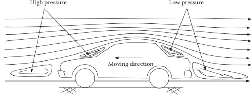
2.2.2 Aerodynamic Drag . . . 21
2.2.3 Grading Resistance . . . 21
2.3 Dynamic Equation . . . .23
2.4 Tire–Ground Adhesion and Maximum Tractive Effort . . . 25
2.5 Power Train Tractive Effort and Vehicle Speed. . . .27
2.6 Vehicle Performance . . . .29
2.6.1 Maximum Speed of a Vehicle. . . 30
2.6.2 Gradeability . . . 31
2.6.3 Acceleration Performance. . . 31
2.7 Operating Fuel Economy . . . .34
2.7.1 Fuel Economy Characteristics of IC Engines . . . 34
2.7.2 Computation of Vehicle Fuel Economy. . . 35
2.7.3 Basic Techniques to Improve Vehicle Fuel Economy . . . 37
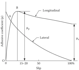
2.8 Brake Performance . . . .38
2.8.1 Braking Force . . . 39
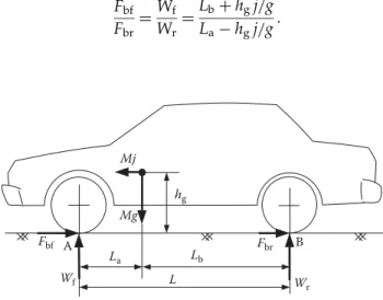
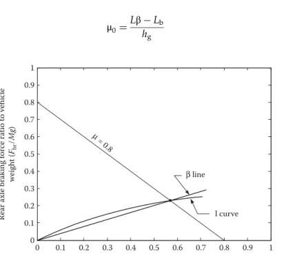
2.8.2 Braking Distribution on Front and Rear Axles . . . 41
2.8.3 Braking Regulation and Braking Performance Analysis . . . 45
2.8.3.1 Braking Regulation . . . 45 vii
2.8.3.2 Braking Performance Analysis. . . 47
Bibliography. . . 49
3. Internal Combustion Engines. . . 51
3.1 Spark Ignition Engine. . . 51
3.1.1 Basic Structure and Operation Principle with Otto Cycle . . . 51
3.1.2 Operation Parameters . . . 53
3.1.2.1 Rating Values . . . 53
3.1.2.2 Indicated Torque and Indicated Mean Effective Pressure . . 53
3.1.2.3 Brake Mean Effective Pressure (bmep) and Brake Torque . . . 56
3.1.2.4 Emission Measurement . . . 57
3.1.2.5 Engine Operation Characteristics . . . 58
3.1.3 Basic Techniques for Improving Engine Performance, Efficiency, and Emissions . . . 59
3.1.3.1 Forced Induction. . . 59
3.1.3.2 Gasoline Direct Injection and Lean-Burn Engines . . . 61
3.1.3.3 Multivalve and Variable Valve Timing . . . 61
3.1.3.4 Variable Compression Ratio . . . 61
3.1.3.5 Exhaust Gas Recirculation . . . 62
3.1.3.6 Intelligent Ignition . . . 62
3.1.3.7 New Engine Materials . . . 62
3.1.4 Brief Review of SI Engine Control System. . . 62
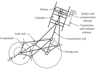
3.1.5 Operation Principle with Atkinson Cycle. . . 64
3.1.5.1 Original Engine with Atkinson Cycle . . . 64
3.1.5.2 Modern Engine with Atkinson Cycle . . . 65
3.2 Compression Ignition Engine . . . .68
3.3 Alternative Fuels and Alternative Fuel Engines . . . .69
3.3.1 Alternative Fuels. . . 69
3.3.1.1 Ethanol and Ethanol Engine . . . 69
3.3.1.2 Compressed Natural Gas and Natural Gas Engine. . . 70
3.3.1.3 Enhanced Hydrogen (H2 Combustion). . . 72
Bibliography. . . 72
4. Vehicle Transmission. . . 73
4.1 Power Plant Characteristics . . . .73
4.2 Transmission Characteristics. . . .76
4.3 Manual Gear Transmission (MT) . . . .78
4.4 Automatic Transmission . . . .81
4.4.1 Conventional Automatic Transmission . . . 82
4.4.1.1 Torque Converter Operation . . . 82
4.4.1.2 Planetary or Epicyclic Gear Train. . . 86
4.4.1.3 Compound Epicyclic Gear. . . 88
4.4.2 Automated Manual and Dual-Clutch Transmission . . . 89
4.5 Continuously Variable Transmission . . . .91
4.6 Infinitely Variable Transmissions . . . 91
4.7 Dedicated Hybrid Transmission (DHT) . . . .92
Bibliography. . . 93
5. Electric Vehicles. . . 95
5.1 Configurations of Electric Vehicles . . . .95
5.2 Performance of Electric Vehicles . . . .98
5.2.1 Traction Motor Characteristics. . . 98
5.2.2 Tractive Effort and Transmission Requirement. . . 99
5.2.3 Vehicle Performance . . . 101
5.3 Tractive Effort in Normal Driving . . . .103
5.4 Energy Consumption . . . .105
Bibliography. . . .110
6. Hybrid Electric Vehicles. . . .113
6.1 Concept of Hybrid Electric Drivetrains . . . .113
6.2 Architectures of Hybrid Electric Drivetrains. . . .116
6.2.1 Series Hybrid Electric Drivetrains (Electrical Coupling) . . . 117
6.2.2 Parallel Hybrid Electric Drivetrains (Mechanical Coupling). . . 119
6.2.2.1 Parallel Hybrid Drivetrain with Torque Coupling. . . 120
6.2.2.2 Parallel Hybrid Drivetrain with Speed Coupling. . . 126
6.2.2.3 Hybrid Drivetrains with Both Torque and Speed Coupling. . . 132
Bibliography. . . .136
7. Electric Propulsion Systems. . . .139
7.1 DC Motor Drives . . . .141
7.1.1 Principle of Operation and Performance . . . 141
7.1.2 Combined Armature Voltage and Field Control . . . 145
7.1.3 Chopper Control of DC Motors . . . 146
7.1.4 Multiquadrant Control of Chopper-Fed DC Motor Drives . . . 149
7.1.4.1 Two-Quadrant Control of Forward Motoring and Regenerative Braking . . . 150
7.1.4.2 Four-Quadrant Operation . . . 153
7.2 Induction Motor Drives . . . .153
7.2.1 Basic Operation Principles of Induction Motors . . . 154
7.2.2 Steady-State Performance. . . 157
7.2.3 Constant Volt/Hertz Control . . . 159
7.2.4 Power Electronic Control . . . 160
7.2.5 Field Orientation Control . . . 163
7.2.5.1 Field Orientation Principles. . . 163
7.2.5.2 Control. . . 170
7.2.5.3 Direct Rotor Flux Orientation Scheme . . . 172
7.2.5.4 Indirect Rotor Flux Orientation Scheme . . . 175
7.2.6 Voltage Source Inverter for FOC . . . 177
7.2.6.1 Voltage Control in Voltage Source Inverter . . . 179
7.2.6.2 Current Control in Voltage Source Inverter . . . 181
7.3 Permanent Magnetic BLDC Motor Drives . . . .184
7.3.1 Basic Principles of BLDC Motor Drives. . . 185
7.3.2 BLDC Machine Construction and Classification. . . 185
7.3.3 Properties of PM Materials . . . 189
7.3.3.1 Alnico. . . 189
7.3.3.2 Ferrites . . . 189
7.3.3.3 Rare-Earth PMs . . . 190
7.3.4 Performance Analysis and Control of BLDC Machines. . . 190
7.3.4.1 Performance Analysis . . . 190
7.3.4.2 Control of BLDC Motor Drives . . . 193
7.3.5 Extend Speed Technology . . . 194
7.3.6 Sensorless Techniques . . . 195
7.3.6.1 Methods Using Measurables and Math. . . 195
7.3.6.2 Methods Using Observers . . . 196
7.3.6.3 Methods Using Back EMF Sensing . . . 196
7.3.6.4 Unique Sensorless Techniques . . . 197
7.4 SRM Drives . . . .198
7.4.1 Basic Magnetic Structure . . . 198
7.4.2 Torque Production. . . 201
7.4.3 SRM Drive Converter. . . 204
7.4.4 Modes of Operation . . . 206
7.4.5 Generating Mode of Operation (Regenerative Braking) . . . 207
7.4.6 Sensorless Control . . . 209
7.4.6.1 Phase Flux Linkage-Based Method . . . 210
7.4.6.2 Phase Inductance-Based Method . . . 211
7.4.6.3 Modulated Signal Injection Methods . . . 212
7.4.6.4 Mutually Induced Voltage-Based Method . . . 214
7.4.6.5 Observer-Based Methods . . . 214
7.4.7 Self-Tuning Techniques of SRM Drives. . . 215
7.4.7.1 Self-Tuning with Arithmetic Method . . . 215
7.4.7.2 Self-Tuning Using an ANN . . . 216
7.4.8 Vibration and Acoustic Noise in SRM . . . 218
7.4.9 SRM Design. . . 220
7.4.9.1 Number of Stator and Rotor Poles. . . 220
7.4.9.2 Stator Outer Diameter . . . 221
7.4.9.3 Rotor Outer Diameter . . . 221
7.4.9.4 Air Gap . . . 222
7.4.9.5 Stator Arc . . . 222
7.4.9.6 Stator Back Iron. . . 222
7.4.9.7 Performance Prediction . . . 222
Bibliography. . . .223
8. Design Principle of Series (Electrical Coupling) Hybrid Electric Drivetrain . . . 229
8.1 Operation Patterns . . . .229
8.2 Control Strategies . . . .231
8.2.1 Max. SOC-of-PPS Control Strategy . . . 232
8.2.2 Engine On–Off or Thermostat Control Strategy . . . 233
8.3 Design Principles of a Series (Electrical Coupling) Hybrid Drivetrain . . . .234
8.3.1 Electrical Coupling Device. . . 234
8.3.2 Power Rating Design of Traction Motor . . . 238
8.3.3 Power Rating Design of Engine/Generator . . . 241
8.3.4 Design of PPS . . . 243
8.3.4.1 Power Capacity of PPS . . . 245
8.3.4.2 Energy Capacity of PPS. . . 245
8.4 Design Example. . . .246
8.4.1 Design of Traction Motor Size . . . 246
8.4.2 Design of Gear Ratio. . . 246
8.4.3 Verification of Acceleration Performance . . . 247
8.4.4 Verification of Gradeability . . . 247
8.4.5 Design of Engine/Generator Size . . . 247
8.4.6 Design of Power Capacity of PPS. . . 249
8.4.7 Design of Energy Capacity of PPS . . . 250
8.4.8 Fuel Consumption . . . 251
Bibliography. . . .252
9. Parallel (Mechanically Coupled) Hybrid Electric Drivetrain Design. . . .255
9.1 Drivetrain Configuration and Design Objectives . . . .255
9.2 Control Strategies . . . .256
9.2.1 Max. SOC-of-PPS Control Strategy . . . 257
9.2.2 Engine On–Off (Thermostat) Control Strategy . . . 260
9.2.3 Constrained Engine On–Off Control Strategy . . . 261
9.2.4 Fuzzy Logic Control Technique . . . 263
9.2.5 Dynamic Programming Technique . . . 264
9.3 Parametric Design of a Drivetrain . . . .267
9.3.1 Engine Power Design . . . 267
9.3.2 Transmission Design. . . 270
9.3.3 Electric Motor Drive Power Design. . . 271
9.3.4 PPS Design. . . 275
9.4 Simulations . . . .277
Bibliography. . . .278
10. Design and Control Methodology of Series–Parallel (Torque and Speed Coupling) Hybrid Drivetrain. . . .281
10.1 Drivetrain Configuration . . . .281
10.1.1 Speed-Coupling Analysis . . . 281
10.1.2 Drivetrain Configuration . . . 283
10.2 Drivetrain Control Methodology . . . .291
10.2.1 Control System . . . 291
10.2.2 Engine Speed Control Approach . . . 291
10.2.3 Traction Torque Control Approach. . . 292
10.2.4 Drivetrain Control Strategies . . . 293
10.2.4.1 Engine Speed Control Strategy . . . 294
10.2.4.2 Traction Torque Control Strategy. . . 296
10.2.4.3 Regenerative Braking Control . . . 298
10.3 Drivetrain Parameter Design . . . .298
10.4 Simulation of an Example Vehicle . . . .299
Bibliography. . . .302
11. Design and Control Principles of Plug-In Hybrid Electric Vehicles . . . .305
11.1 Statistics of Daily Driving Distance . . . .305
11.2 Energy Management Strategy . . . .306
11.2.1 AER-Focused Control Strategy . . . 307
11.2.2 Blended Control Strategy . . . 312
11.3 Energy Storage Design. . . .320
Bibliography. . . .322
12. Mild Hybrid Electric Drivetrain Design. . . .323
12.1 Energy Consumed in Braking and Transmission . . . .323
12.2 Parallel Mild Hybrid Electric Drivetrain . . . .325
12.2.1 Configuration . . . 325
12.2.2 Operating Modes and Control Strategy . . . 325
12.2.3 Drivetrain Design . . . 326
12.2.4 Performance . . . 329
12.3 Series–Parallel Mild Hybrid Electric Drivetrain. . . .330
12.3.1 Configuration of Drivetrain with Planetary Gear Unit . . . 330
12.3.2 Operating Modes and Control. . . 336
12.3.2.1 Speed-Coupling Operating Mode . . . 336
12.3.2.2 Torque-Coupling Operating Mode . . . 337
12.3.2.3 Engine-Alone Traction Mode . . . 338
12.3.2.4 Motor-Alone Traction Mode. . . 338
12.3.2.5 Regenerative Braking Mode . . . 339
12.3.2.6 Engine Starting . . . 339
12.3.3 Control Strategy . . . 339
12.3.4 Drivetrain with Floating-Stator Motor. . . 340
Bibliography. . . .341
13. Peaking Power Sources and Energy Storage. . . 343
13.1 Electrochemical Batteries. . . .343
13.1.1 Electrochemical Reactions . . . 345
13.1.2 Thermodynamic Voltage . . . 346
13.1.3 Specific Energy . . . 347
13.1.4 Specific Power . . . 349
13.1.5 Energy Efficiency . . . 351
13.1.6 Battery Technologies. . . 351
13.1.6.1 Lead–Acid Battery . . . 352
13.1.6.2 Nickel-Based Batteries . . . 353
13.1.6.3 Lithium-Based Batteries . . . 355
13.2 Ultracapacitors . . . .356
13.2.1 Features of Ultracapacitors . . . 356
13.2.2 Basic Principles of Ultracapacitors . . . 357
13.2.3 Performance of Ultracapacitors . . . 358
13.2.4 Ultracapacitor Technologies . . . 361
13.3 Ultra-High-Speed Flywheels . . . .363
13.3.1 Operation Principles of Flywheels . . . 363
13.3.2 Power Capacity of Flywheel Systems. . . 365
13.3.3 Flywheel Technologies. . . 367
13.4 Hybridization of Energy Storages . . . .369
13.4.1 Concept of Hybrid Energy Storage . . . 369
13.4.2 Passive and Active Hybrid Energy Storage with Battery and Ultracapacitor. . . 370
13.4.3 Battery and Ultracapacitor Size Design. . . 371
Bibliography. . . .374
14. Fundamentals of Regenerative Braking. . . .377
14.1 Braking Energy Consumed in Urban Driving . . . .377
14.2 Braking Energy versus Vehicle Speed . . . .378
14.3 Braking Energy versus Braking Power . . . .381
14.4 Braking Power versus Vehicle Speed . . . .381
14.5 Braking Energy versus Vehicle Deceleration Rate . . . .382
14.6 Braking Energy on Front and Rear Axles . . . .383
14.7 Brake System of EV, HEV, and FCV . . . .384
14.7.1 Parallel Hybrid Brake System . . . 385
14.7.1.1 Design and Control Principles with Fixed Ratios between Electric and Mechanical Braking Forces . . . 386
14.7.1.2 Design and Control Principles for Maximum Regenerative Braking . . . 387
14.7.2 Fully Controllable Hybrid Brake System . . . 390
14.7.2.1 Control Strategy for Optimal Braking Performance . . . 391
14.7.2.2 Control Strategy for Optimal Energy Recovery . . . 392
Bibliography. . . .394
15. Fuel Cells . . . .397
15.1 Operation Principles of Fuel Cells . . . .397
15.2 Electrode Potential and Current–Voltage Curve . . . .400
15.3 Fuel and Oxidant Consumption . . . .403
15.4 Fuel Cell System Characteristics . . . .404
15.5 Fuel Cell Technologies . . . .406
15.5.1 Proton Exchange Membrane Fuel Cells. . . 406
15.5.2 Alkaline Fuel Cells. . . 407
15.5.3 Phosphoric Acid Fuel Cells . . . 409
15.5.4 Molten Carbonate Fuel Cells . . . 410
15.5.5 Solid Oxide Fuel Cells . . . 410
15.5.6 Direct Methanol Fuel Cells . . . 411
15.6 Fuel Supply . . . .412
15.6.1 Hydrogen Storage . . . 412
15.6.1.1 Compressed Hydrogen . . . 412
15.6.1.2 Cryogenic Liquid Hydrogen. . . 414
15.6.1.3 Metal Hydrides . . . 414
15.6.2 Hydrogen Production . . . 416
15.6.2.1 Steam Reforming . . . 416
15.6.2.2 POX Reforming . . . 417
15.6.2.3 Autothermal Reforming . . . 417
15.6.3 Ammonia as Hydrogen Carrier. . . 418
15.7 Non-Hydrogen Fuel Cells . . . .418
Bibliography. . . .419
16. Fuel Cell Hybrid Electric Drivetrain Design. . . 421
16.1 Configuration . . . .421
16.2 Control Strategy . . . .423
16.3 Parametric Design . . . .424
16.3.1 Motor Power Design. . . 425
16.3.2 Power Design of Fuel Cell System . . . 425
16.3.3 Design of Power and Energy Capacity of PPS. . . 426
16.3.3.1 Power Capacity of PPS . . . 426
16.3.3.2 Energy Capacity of PPS. . . 426
16.4 Design Example. . . .428
Bibliography. . . .430
17. Design of Series Hybrid Drivetrain for Off-Road Vehicles. . . 431
17.1 Motion Resistance. . . .431
17.1.1 Motion Resistance Caused by Terrain Compaction. . . 432
17.1.2 Motion Resistance Caused by Terrain Bulldozing . . . 434
17.1.3 Internal Resistance of Running Gear . . . 435
17.1.4 Tractive Effort of Terrain . . . 436
17.1.5 Drawbar Pull . . . 437
17.2 Tracked Series Hybrid Vehicle Drivetrain Architecture . . . .437
17.3 Parametric Design of Drivetrain . . . .438
17.3.1 Traction Motor Power Design . . . 439
17.3.1.1 Vehicle Thrust versus Speed. . . 439
17.3.1.2 Motor Power and Acceleration Performance . . . 440
17.3.1.3 Motor Power and Gradeability . . . 441
17.3.1.4 Steering Maneuver of a Tracked Vehicle . . . 443
17.4 Engine/Generator Power Design . . . .447
17.5 Power and Energy Design of Energy Storage. . . .449
17.5.1 Peaking Power for Traction. . . 449
17.5.2 Peaking Power for Nontraction. . . 450
17.5.3 Energy Design of Batteries/Ultracapacitors . . . 452
17.5.4 Combination of Batteries and Ultracapacitors . . . 452
Bibliography. . . .454
18. Design of Full-Size-Engine HEV with Optimal Hybridization Ratio. . . .457
18.1 Design Philosophy of Full-Size-Engine HEV . . . .457
18.2 Optimal Hybridization Ratio . . . .459
18.2.1 Simulation under Highway Driving Conditions. . . 459
18.2.2 Optimal Hybridization of Electrical Drive Power . . . 463
18.3 10–25 kW Electrical Drive Packages . . . .463
18.3.1 Sensitivity to Engine Peak Power. . . 464
18.3.2 Sensitivity to Vehicle Mass . . . 464
18.3.3 10–25 kW Electrical Drive Power Window . . . 464
18.3.4 Electrical Drive Package for Passenger Cars . . . 468
18.4 Comparison with Commercially Available Passenger Cars . . . .468
18.4.1 Comparison with 2011 Toyota Corolla . . . 469
18.4.2 Comparison with 2011 Toyota Prius Hybrid . . . 470
Bibliography. . . .471
19. Powertrain Optimization. . . .473
19.1 Powertrain Modeling Techniques. . . .473
19.1.1 Forward-Facing Vehicle Model . . . 473
19.1.2 Backward-Facing Vehicle Model . . . 474
19.1.3 Comparison of Forward-Facing and Backward-Facing Models . . . 475
19.2 Defining Performance Criteria . . . .475
19.2.1 Tank-to-Wheel Emissions. . . 476
19.2.2 Well-to-wheel Emissions. . . 477
19.3 Powertrain Simulation Methods . . . .478
19.4 Modular Powertrain Structure . . . .480
19.4.1 Framework of Proposed Toolbox . . . 480
19.4.2 Modular Powertrain Structure. . . 480
19.4.3 Optimizer . . . 484
19.5 Optimization Problem . . . .485
19.5.1 Extending Optimizer to Support Multiple Powertrain Topologies . . . 487
19.5.2 Multiobjective Optimization . . . 487
19.6 Case Studies: Optimization of Powertrain Topology and Component Sizing . . . .488
19.6.1 Case Study 1: Tank-to-Wheel versus Well-to-Wheel CO2. . . 489
19.6.1.1 Lowest Well-to-Wheel CO2Emissions. . . 490
19.6.1.2 Lowest Tank-to-Wheel CO2Emission . . . 491
19.6.1.3 Multiobjective Optimization . . . 492
19.6.2 Case Study 2: Powertrain Cost versus Well-to-Wheel CO2. . . 494
Bibliography. . . .497
20. User Guide for Multiobjective Optimization Toolbox. . . .499
20.1 About the Software . . . .499
20.2 Software Structure . . . .499
20.2.1 Input Sheet. . . 499
20.2.2 Genetic Algorithm . . . 500
20.2.3 Fitness Evaluation Algorithm. . . 500
20.2.4 Simulation of Vehicle Configurations. . . 500
20.2.5 Component Models Available . . . 500
20.2.6 Running a Simulation . . . 501
20.2.6.1 Definition of Drive Cycle . . . 501
20.2.6.2 Selection of Cost Function . . . 501
20.2.6.3 Power Train Type Selection. . . 502
20.2.6.4 Advanced Settings . . . 503
20.2.7 Running the Simulation . . . 503
20.2.8 Results . . . 505
20.3 Capabilities and Limitations of Software . . . .506
Appendix: Technical Overview of Toyota Prius. . . 507
Index. . . .525
Electric and Hybrid Electric vehicles are now well known products in the market and are accepted internationally. However, their full potential for penetrating the automobile mar- ket is not yet fulfilled, even with the ever expanding awareness of the global warming prob- lem due to the fossil fuel use. This is, in part, due to the low cost and ever abundance of fossil fuels for the conventional internal combustion engine vehicles. The abundance of hydrocar- bon fuels is not going the change for decades and perhaps for centuries. Therefore, the elec- tric and hybrid electric vehicles will dominate the automobile market only if they provide better and more appropriate products for the present and future needs of the automobile user. For example, a very low cost electric vehicle can dominate the market in the developing countries with no fossil fuel resourses of their own, where conventional cars are too expen- sive for the middle class family to purchase and operate. Further, a conventional vehicle, with full size internal combustion engine, can be optimized for performance, fuel economy, emissions, and cost, by a small traction motor/generator hybridization. Such a vehicle can be a superior product, in comparison to the conventional cars, with a small incremental cost, for the developed world markets.
The present third edition of our book contributes to the above aims by introducing appro- priate technologies and design methodologies. Further, the present edition benefits from the suggestions of many readers, students and academic adopters of the previous editions of this book, whose suggestions is gratefully acknowledged.
The development of the internal combustion engine automobiles is one of the greatest achievements of the modern technology. However, the highly developed automotive indus- try and the increasingly large number of automobiles in use around the world are causing serious problems for the environment and hydrocarbon resources. The deteriorating air quality and global warming issues are becoming serious threats to modern life. Progres- sively more rigorous emissions and fuel efficiency standards are stimulating aggressive development of safer, cleaner, and more efficient vehicles. It is now well recognized that electric, hybrid electric, and fuel cell powered drive train technologies are the most promis- ing vehicle solutions for the foreseeable future.
To meet this challenge, an increasing number of engineering schools, in the US and around the world, have initiated academic programs in advanced energy and vehicle tech- nologies at undergraduate and graduate levels. We stared ourfirst graduate course, In 1998, on“Advanced Vehicle Technologies—Design Methodology of Electric and Hybrid Electric Vehicles”for students in mechanical and electrical engineering at Texas A&M University.
While preparing the lectures for this course, we found that although there is a wealth of information in the form of technical papers and reports, there was no rigorous and compre- hensive textbook for students and professors that may wish to offer such a course. Further- more, practicing engineers also needed a systematic reference book to fully understand the essentials of this new technology. Thefirst edition of this book was our attempt tofill this need. The present third edition introduces newer topics and deeper treatments to the previ- ous editions.
The book deals with the fundamentals, theoretical bases, and design methodologies of conventional internal combustion engines (ICE) vehicles, electric vehicles (EV), hybrid elec- tric vehicles (HEV), and fuel cell vehicles (FCV). It comprehensively covers vehicle perfor- mance characteristics, configurations, control strategies, design methodologies, modeling, xvii
and simulation for modern vehicles with mathematical rigor. It includes drive train architec- ture analysis, ICE based drive trains, EV and HEV configurations, electric propulsion sys- tems, series/parallel/mild hybrid electric drive train design methodologies, energy storage systems, regenerative braking, fuel cells and their applications in vehicles, and fuel cell hybrid electric drive train design. The book perspective is from the overall drive train system and not just individual components. The design methodology is described in mathematical terms, step by step. Furthermore, in explaining the design methodology of each drive train, design examples are presented with simulation results.
More specifically, the third edition contains many corrections and updates of the material in thefirst and second editions. Four new chapters and one appendix have been added. They areChapter 4: Vehicle Transmission;Chapter 18: Design of Full-Size Engine HEV with Opti- mal Hybridization Ratio; Chapter 19: A User Guide for the Multiobjective Optimization Toolbox; andChapter 20: Power Train Optimization, plus the Appendix: Technical Over- view of Toyota Prius. In addition, plenty of new materials have been added to the old chap- ters. All these new contributions to the third edition make it more complete and useful to the reader.
Overall, this book consists of twenty chapters and one appendix. InChapter 1, the social and environmental importance of modern transportation is discussed. This includes the air pollution, global warming, and petroleum resource depletion issues associated with the development of the modern transportation. In this chapter, the impact of future vehicle tech- nologies on the oil supplies is analyzed. The results are helpful for the development strate- gies of the next generation vehicles. In addition, the development history of EV, HEV, and FCV is briefly reviewed.
InChapter 2, the basic understanding of vehicle performance, power plant characteristics, transmission characteristics, and the equations used to describe the vehicle performance are introduced. The main purpose of this chapter is to provide the basic knowledge that is nec- essary for vehicle drive train design. As an improvement to thefirst edition, the brake sys- tem and its design and performance material has been strengthened in order to provide a more solid base for the hybrid brake system design in EV, HEV and FCV.
InChapter 3, major operating characteristics of different heat engines are introduced. As the primary power plant, the engine is the most important subsystem in conventional and hybrid drive train systems. Full understanding of the characteristics of engine is necessary in design and control of conventional as well as hybrid electric vehicles.
InChapter 4, vehicle transmission for conventional and hybrid electric vehicle is intro- duced. Most kinds of conventional and advanced transmission systems are presented and analyzed.
InChapter 5, electric vehicles are introduced. This chapter mainly includes design of the electric propulsion system and its energy storage device, design of the traction motor and its transmission, methodology of prediction of vehicle performance, and system simulation results.
InChapter 6, the basic concept of hybrid traction isfirst established. Then, various config- urations of hybrid electric vehicles are discussed. These include series hybrid, parallel hybrid, torque coupling and speed coupling hybrids, and other configurations. The main operating characteristics of these configurations are also presented.
InChapter 7, several electric power plants are introduced. These include DC, AC, perma- nent magnet brushless DC, and switched reluctance motor drives. From traction system point of view, their basic structure, operating principles, control and operational character- istics are described.
InChapter 8, the design methodology of series hybrid electric drive trains is presented.
This chapter is focused on the system oriented design of the engine and energy storage, the traction motor, the transmission, the control strategy, and the power converters. A design example is also provided. As an improvement to thefirst edition, various power con- verter configurations have been added.
InChapter 9, a design methodology of parallel hybrid electric drive trains is provided.
This chapter includes driving patterns and driving mode analysis, control strategy, design of the major components, e.g., the engine, the energy storage, and the transmission, and vehicle performance simulation. In addition to thefirst edition, a constrained engine on and off control strategy, fuzzy logic control strategy and the concept of control optimization based on dynamic programming have been added.
InChapter 10, the operating characteristics, design methodology, and control strategies of series-parallel hybrid drive train is presented. This was a new chapter in the second edition.
InChapter 11, the design and control principles of the plug-in hybrid vehicle is intro- duced. This chapter mainly addresses the charge sustaining hybrid drive train with regard to the drivetrain control strategy, energy storage design, and electric motor design. This was also a new chapter.
InChapter 12, a design methodology of mild hybrid drive trains is introduced with the two major configurations of parallel torque coupling and series/parallel, torque-speed cou- pling. This chapter is focused on the operational analysis, control system development, and system simulation.
InChapter 13, different energy storage technologies are introduced, including batteries, ultra-capacitors, andflywheels. The discussion focuses on the power and energy capacities.
The concept of hybrid energy storage is also introduced in this chapter.
InChapter 14, the design and control principles of hybrid brake systems are introduced.
Brake safety and the recoverable energy are the main concerns. The available braking energy characteristics, with regard to vehicle speed, and the braking power in typical driving cycles are investigated. The brake force distribution on the front and rear wheels is discussed for guaranteeing the vehicle braking performance for safety. Furthermore, this chapter dis- cusses the important issue of distributing the total braking force between the mechanical and the electrical regenerative brakes. Two advanced hybrid brake systems, including their control strategies are introduced. This chapter has been rewritten based on our recent research.
InChapter 15, different fuel cell systems are described, with the focus on their operating principles and characteristics, various technologies, and their fuels. Specifically, vehicle applications of fuel cells are explained.
InChapter 16, a systematic design of fuel cell hybrid drive trains is introduced. First, the concept of fuel cell hybrid vehicles is established. Then, their operating principles and driv- etrain control systems are analyzed. Lastly, a design methodology is provided, focusing on the system design of the fuel cell, the electric propulsion system, and the energy storage sys- tem. A design example and its corresponding performance simulation results are provided.
InChapter 17, a design methodology of an off-road tracked series hybrid vehicle is devel- oped. The discussion focuses on the motion resistance calculation on soft grounds, traction motor system design, the engine/generator system design and the peaking power source system design.
Chapters 18,19, and20are new chapters for the third edition. They introduce the new full size engine optimal hybrid vehicle design concept, and general hybridization of vehicle power plant and its associated software.
A case study appendix is included in the present edition. This is an overview of the Toyota Prius hybrid system. The purpose is to give the reader a practical example of the architec- ture, operational modes, control system, among other things, of a commercial hybrid electric drive train.
This book is suitable for a graduate or senior-level undergraduate course in advanced vehicles. Software (©2018 by Ganesh Mohan, Francis Assadian, Marcin Stryszowski, and Stefano Longo) designed to accompany the material in this book will be hosted on the book's CRC Press website:www.crcpress.com/9781498761772.Depending on the background of the students in different disciplines such as mechanical or electrical engineering, course instructors have theflexibility of choosing the specialized material to suit their lectures.
This text has been taught at Texas A&M University as a graduate level course for two decades. The manuscript of this text has been revised many times and over many years, based on the comments and feedback from the students in our course. We are grateful to our students for their help.
This book is also an in-depth resource and a comprehensive reference in modern automo- tive systems for engineers, students, researchers, and other professionals who are working in the automotive related industries, as well those in the government, and academia.
In addition to the work by others, many of the technologies and advances presented in this book are the collection of many years of research and development by the authors and other members of the Advanced Vehicle Systems Research Program at Texas A&M Uni- versity. We are grateful to all the dedicated staff of the Advanced Vehicle Systems Research group and the Power Electronics and Motor Drives group at Texas A&M, who made great contributions to this book.
We would like to acknowledge the efforts and assistance of the staff of Taylor & Francis Group, especially Ms. Nora Konopka. Last but not least, we thank our families for their patience and support during the long effort in the writing of this book.
Mehrdad Ehsani Yimin Gao Stefano Longo Kambiz Ebrahimi January, 2018 MATLAB®and Simulink®are registered trademark of The MathWorks, Inc. For product information, please contact:
The MathWorks, Inc.
3 Apple Hill Drive
Natick, MA 01760-2098 USA Tel: 508-647-7000
Fax: 508-647-7001
E-mail: [email protected] Web:www.mathworks.com
Many of our past and present students and research staff have contributed to the work that has resulted in this book, over the past two decades. In particular, we acknowledge the work of Lin Lai who contributed to Chapter 18 through his PhD dissertation at Texas A&M University. We also acknowledge the help of our PhD students Nima Ersahd, Ahmet Yeksan, Own Golden, and Yiqi Wang, all of Texas A&M University Advanced Vehicle Sys- tems Research Program.
For the chapters“Optimization Techniques for Power Train Topology and Component Sizing”and“A User Guide for the Multiobjective Optimization Toolbox”and for the soft- ware provided with this book, the authors would like to acknowledge the contribution of Dr. Ganesh Mohan, Professor Francis Assadian, and Mr Marcin Staszowski. Dr. Mohan was a PhD student at Cranfield University, UK, when he developed the techniques for power train optimization and the MATLAB®-based software that is available with this book. He is now an engineer at Jaguar Land Rover. Professor Assadian, his primary super- visor, directed most of this work before accepting a professorship at the University of California Davis, USA. Mr Staszowski is a current PhD student at Cranfield University.
He helped develop the material for the two aforementioned chapters and improved the soft- ware functionalities. We would like to express our gratitude to them for the exceptional con- tribution they have made with their work and for allowing us to publish it.
xxi
Mehrdad Ehsani is the Robert M. Kennedy Professor of Electrical Engineering at Texas A&M University. From 1974 to 1981, he was a research engineer at the Fusion Research Center, University of Texas, and with Argonne National Laboratory, Argonne, Illinois, as a resident research associate. Since 1981 he has been at Texas A&M University, College Station, Texas, where he is now an endowed professor of electrical engineering and director of the Advanced Vehicle Systems Research Program and the Power Electronics and Motor Drives Laboratory. He is the author of over 400 publications in pulsed-power sup- plies, high-voltage engineering, power electronics, motor drives, advanced vehicle systems, and sustainable energy engineering. He is the recipient of several Prize Paper Awards from the IEEE-Industry Applications Society, as well as over 100 other international honors and recognitions, including the IEEE Vehicular Soci- ety 2001 Avant Garde Award for“contributions to the theory and design of hybrid elec- tric vehicles.”In 2003, he was selected for the IEEE Undergraduate Teaching Award“for outstanding contributions to advanced curriculum development and teaching of power electronics and drives.”In 2005, he was elected Fellow of the Society of Automotive Engi- neers (SAE). He is the coauthor of 17 books on power electronics, motor drives, and advanced vehicle systems. He has over 30 granted or pending U.S. and EU patents.
His current research work is in power electronics, motor drives, hybrid vehicles and their control systems, and sustainable energy engineering.
Dr. Ehsani has been a member of IEEE Power Electronics Society (PELS) AdCom, chair- man of the PELS Educational Affairs Committee, chairman of the IEEE-IAS Industrial Power Converter Committee, and chairman of the IEEE Myron Zucker Student- Faculty Grant program. He was the general chair of the IEEE Power Electronics Specialist Conference in 1990. He is the founder of IEEE Power and Propulsion Conference, the founding chairman of IEEE VTS Vehicle Power and Propulsion, and chairman of Convergence Fellowship Committees. In 2002, he was elected to the board of governors of VTS. He has also served on the editorial board of several technical journals and was the associate editor of IEEE Transactions on Industrial Electronics and IEEE Transactions on Vehicular Technology. He is a life time fellow of IEEE, a past IEEE Industrial Electronics Society and Vehicular Technology Society distinguished speaker, and IEEE Industry Applications Society and Power Engineering Society distinguished lecturer. He is also a registered professional engineer in the state of Texas.
xxiii
Yimin Gaoreceived his BS, MS, and PhD degrees in mechanical engineering (major in the development, design, and manufactur- ing of automotive systems) in 1982, 1986, and 1991, respectively, all from Jilin University of Technology, Changchun, Jilin, China.
From 1982 to 1983, he worked as a vehicle design engineer at Dongfeng Motor Company, Shiyan, Hubei, China. He finished a layout design of a 5-ton truck (EQ144) and participated in prototyping and testing. From 1983 to 1986, he was a graduate student in Automotive Engineering College of Jilin University of Technology, Changchun, Jilin, China. His working field was the improvement of vehicle fuel economy by optimal matching of engine and transmission.
From 1987 to 1992, he was a PhD student in the Automotive Engineering College of Jilin University of Technology, Changchun, Jilin, China. During this period, he worked on research and development of legged vehicles, which can poten- tially operate in harsh environments where mobility is difficult for wheeled vehicles.
From 1991 to 1995, he was an associate professor and automotive design engineer in the Automotive Engineering College of Jilin University of Technology. In this period, he taught undergraduate students a course in automotive theory and design several times and graduate students a course in automotive experiment technique twice. Meanwhile, he also conducted vehicle performance, chassis, and components analysis, and he conducted automotive design, including chassis design, power train design, suspension design, steer- ing system design, and brake design.
He joined the Advanced Vehicle Systems Research Program at Texas A&M University in 1995 as a research associate. Since then, he has been working in this program on research and development of electric and hybrid electric vehicles. His research areas are mainly in the fundamentals, architecture, control, modeling, design, and major components of electric and hybrid electric drivetrains. He is a member of SAE.
Stefano Longo, after graduating in electrical and electronic engi- neering, received his MSc in control systems from the University of Sheffield, UK, in 2007 and his PhD, also in control systems, from the University of Bristol, UK, in 2010. His PhD thesis was awarded the Institution of Engineering and Technology (IET) Control and Automation Prize for significant achievements in the area of control engineering. In 2010, he was appointed to the position of research associate at Imperial College London, UK, in the Control and Power Group within the Department of Electrical and Electronic Engineering, where he worked at the intersection of control systems design and hardware implementation. In 2012, he was appointed lecturer (assistant professor) in vehicle electrical and electronic systems at Cranfield University, UK, within the Automotive Engineering Department (now called the Advanced Vehicle Engineering Centre). From 2012 to 2016, he was also an honorary research associate at Imperial College London. In 2017, Dr. Longo was promoted to the position of senior lecturer (associate professor) in automotive control and optimization, and he has been the course director for the MSc in automotive mecha- tronics since 2014.
Dr. Longo has published over 70 peer-reviewed research articles and another book, Optimal and Robust Scheduling for Networked Control Systems, (CRC Press, 2017). He teaches various postgraduate courses in automotive mechatronics, optimization, and control, super- vises PhD students, and conducts academic research and consultancy.
Dr. Longo is a senior member of the IEEE, an associate editor of the Elsevier journal Mechatronics, a technical editor and reviewer for many IEEE and IFAC journals, a chartered engineer and elected executive member of the IET Control & Automation Network, a member of the IFAC technical committee on Mechatronic Systems and Automotive Control, and a fellow of the Higher Education Academy.
Kambiz M. Ebrahimi, PhD, received his BSc degree in mechan- ical engineering from Plymouth Polytechnic, UK, his M.Eng degree in systems engineering from UWIST, University of Wales, and his PhD in dynamics and mathematical modeling from Cardiff University, UK.
Currently, he is professor of advanced propulsion in the Aeronautical and Automotive Engineering Department at Loughborough University, UK. Before joining Loughborough, he worked as a research assistant at the University of Wales working on model-based condition monitoring on an EU pro- ject and at the University of Bradford on distributed—lumped modeling and least effort control strategies. Subsequently, he became a lecturer, reader, and professor of mechanical engineering at the University of Bradford, UK.
His main research interests are in systems and control theory; multivariable and large- scale systems; modeling and characterization of mechatronic systems; energy management and control of hybrid power trains; system monitoring, fault diagnosis, and turbomachinery tip-timing; hybrid, electric, and L-category vehicles. He is the author or coauthor of more than 100 articles in national and international journals and conferences.
Dr. Ebrahimi is a chartered mechanical engineer and member of ASME and SAE and has served as the chair and organizer of the Powertrain Modelling and Control Conference since 2012; a member of the editorial board ofInternational Journal of Powertrainssince 2012; and the Organizer of Meeting the Challenges in Powertrain Testing, in 2009. He is also a member of the editorial board of theProceedings of the Institution of Mechanical Engineers, Part K, Jour- nal of Multi-body Dynamics, as well as the coeditor of the 1998 book Application of Multi- Variable System Techniques, Professional Engineering Publishing, and coeditor of the 2000 bookMulti-Body Dynamics, Professional Engineering Publishing.
He is actively involved in research collaboration with industry through contacts such as AVL, Ford Motor Company, Cummins Turbocharger Technologies, Jaguar, and Land Rover.
Environmental Impact and History of Modern Transportation
The development of internal combustion (IC) engine vehicles, and especially automobiles, is one of the greatest achievements of modern technology. Automobiles have made great con- tributions to the growth of modern society by satisfying many of the needs for mobility in everyday life. The rapid development of the automotive industry, unlike that of any other industry, has prompted the progress of human beings from a primitive society to a highly developed industrial one. The automobile industry and the other industries that serve it constitute the backbone of the world’s economy and employ the greatest share of the working population.
However, the large number of automobiles in use around the world has caused and con- tinues to cause serious problems for the environment and human life. Air pollution, global warming, and the rapid depletion of the Earth’s petroleum resources are now problems of paramount concern.
In recent decades, the research and development activities related to transportation have emphasized the development of high-efficiency, clean, and safe transportation. Electric vehicles (EVs), hybrid electric vehicles (HEVs), and fuel cell vehicles have been typically proposed to replace conventional vehicles in the near future.
This chapter reviews the problems of air pollution, gas emissions causing global warming, and petroleum resource depletion. It also briefly reviews the history of EVs, HEVs, and fuel cell technology.
1.1 Air Pollution
At present, all vehicles rely on the combustion of hydrocarbon (HC) fuels to derive the energy necessary for their propulsion. Combustion is a reaction between the fuel and the air that releases heat and combustion products. The heat is converted to mechanical power by an engine, and the combustion products are released into the atmosphere.
An HC is a chemical compound with molecules made up of carbon and hydrogen atoms. Ideally, the combustion of an HC yields only carbon dioxide and water, which do not harm the environment. Indeed, green plants “digest” carbon dioxide by photo- synthesis. Carbon dioxide is a necessary ingredient in vegetal life. Animals do not suffer by breathing carbon dioxide unless its concentration in air is such that oxygen is almost absent.
The combustion of HC fuel in combustion engines is never ideal. Besides carbon dioxide and water, the combustion products contain a certain amount of nitrogen oxides (NOx), carbon monoxides (CO), and unburned HCs, all of which are toxic to human health.
1
1.1.1 Nitrogen Oxides
Nitrogen oxides (NOx) result from the reaction between nitrogen in the air and oxygen. The- oretically, nitrogen is an inert gas. However, the high temperatures and pressures in engines create favorable conditions for the formation of nitrogen oxides. Temperature is by far the most important parameter in nitrogen oxide formation. The most commonly found nitrogen oxide is nitric oxide (NO), although small amounts of nitric dioxide (NO2) and traces of nitrous oxide (N2O) are present. Once released into the atmosphere, NO reacts with oxygen to form NO2. This is later decomposed by the Sun’s ultraviolet radiation back to NO and highly reactive oxygen atoms that attack the membranes of living cells. Nitrogen dioxide is partly responsible for smog; its brownish color makes smog visible. It also reacts with atmo- spheric water to form nitric acid (HNO3), which dilutes in rain. This phenomenon is referred to as“acid rain”and is responsible for the destruction of forests in industrialized countries.1 Acid rain also contributes to the degradation of historical monuments made of marble.1 1.1.2 Carbon Monoxide
Carbon monoxide results from the incomplete combustion of HCs due to a lack of oxygen.1 It is a poison to human beings and animals that inhale/breathe it. Once carbon monoxide reaches blood cells, it attaches to the hemoglobin in place of oxygen, thereby diminishing the quantity of oxygen that reaches the organs and reducing the physical and mental abilities of the affected living beings.1Dizziness is thefirst symptom of carbon monoxide poisoning, which can rapidly lead to death. Carbon monoxide binds more strongly to hemo- globin than oxygen. The bonds are so strong that normal body functions cannot break them.
People intoxicated by carbon monoxide must be treated in pressurized chambers, where the pressure makes it easier to break the carbon monoxide–hemoglobin bonds.
1.1.3 Unburned HCs
Unburned HCs are a result of the incomplete combustion of HCs.1,2Depending on their nature, unburned HCs may be harmful to living beings.2Some of these unburned HCs may be direct poisons or carcinogenic chemicals such as particulates, benzene, or others.
Unburned HCs are also responsible for smog; the Sun’s ultraviolet radiation interacts with the unburned HCs and NO in the atmosphere to form ozone and other products. Ozone is a molecule formed by three oxygen atoms. It is colorless but very dangerous and poisonous because it attacks the membranes of living cells, causing them to age prematurely or die. Tod- dlers, older people, and asthmatics suffer greatly from exposure to high ozone concentra- tions. Annually, deaths from high ozone peaks in polluted cities have been reported.3 1.1.4 Other Pollutants
Impurities in fuels result in the emission of pollutants. The major impurity is sulfur, mostly found in diesel and jet fuel but also in gasoline and natural gas.1The combustion of sulfur (or sulfur compounds such as hydrogen sulfide) with oxygen releases sulfur oxides (SOx). Sul- fur dioxide (SO2) is the major product of this combustion. On contact with air, it forms sulfur trioxide, which later reacts with water to form sulfuric acid, a major component of acid rain.
It should be noted that sulfur oxide emissions originate from transportation sources but also largely from the combustion of coal in power plants and steel factories. In addition, there is debate over the exact contribution of natural sources such as volcanoes.
Petroleum companies add chemical compounds to their fuels to improve the performance or lifetime of engines.1 Tetraethyl lead, often referred to simply as “lead,”was used to improve the knock resistance of gasoline and, thereby, produce better engine performance.
However, the combustion of this chemical releases lead metal, which is responsible for a neurological disease called saturnism. Its use is now forbidden in most developed countries, and it has been replaced by other chemicals.1
1.2 Global Warming
Global warming is a result of the greenhouse effect induced by the presence of carbon diox- ide and other gases, such as methane, in the atmosphere. These gases trap the Sun’s infrared radiation reflected from the ground, thus retaining the energy in the atmosphere and increasing the temperature. An increased Earth temperature results in major ecological damage to ecosystems and in many natural disasters that affect human populations.2
Considering the ecological damage induced by global warming, the disappearance of some endangered species is a concern because this destabilizes the natural resources that feed some populations. There are also concerns about the migration of some species from warm seas to previously colder northern seas, where they can potentially destroy indige- nous species and the economies that live off those species. This may be happening in the Mediterranean Sea, where barracudas from the Red Sea have been observed.
Natural disasters command our attention more than ecological disasters because of the magnitude of the damage they cause. Global warming is believed to have induced meteo- rological phenomena such as El Niño, which disturbs the South Pacific region and regularly causes tornadoes, floods, and droughts. The melting of the polar icecaps, another major result of global warming, raises the sea level and can cause the permanent inundation of coastal regions and sometimes of entire countries.
Carbon dioxide is the result of the combustion of HCs and coal. Transportation accounts for a large share (32% from 1980 to 1999) of carbon dioxide emissions. The distribution of carbon dioxide emissions is shown inFigure 1.1.4
Residential 19%
Commercial 15%
Industrial 34%
Transportation 32%
FIGURE 1.1
Carbon dioxide emission distribution from 1980 to 1999.
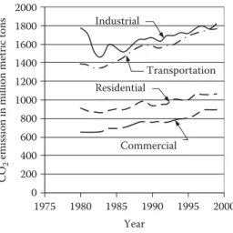
Figure 1.2shows the trend in carbon dioxide emissions. The transportation sector is clearly now the major contributor to carbon dioxide emissions. It should be noted that developing countries are rapidly increasing their transportation sector, and these countries represent a very large share of the world’s population. Further discussion of this issue is provided in the next subsection.
The large amounts of carbon dioxide released into the atmosphere by human activities are believed to be largely responsible for the increase in the global temperature on Earth observed in recent decades (Figure 1.3). It is important to note that carbon dioxide is indeed digested by plants and sequestrated by oceans in the form of carbonates. However, these natural assimilation processes are limited and cannot assimilate all emitted carbon dioxide, resulting in an accumulation of carbon dioxide in the atmosphere.
0 200 400 600 800 1000 1200 1400 1600 1800 2000
1975 1980 1985 1990 1995 2000 Year
CO2 emission in million metric tons
Industrial
Transportation Residential
Commercial
FIGURE 1.2
Evolution of CO2emission.
–1 –0.8 –0.6 –0.4 –0.2 0 0.2 0.4 0.6
1861 1871 1881 1891 1901 1911 1921 1931 1941 1951 1961 1971 1981 1991 Global temperature changes (1861–1996) EPA
Year
0 0.11 –0.11 0.22 0.33
–0.22 –0.33 –0.44 –0.56
DFo DCo
FIGURE 1.3
Global Earth atmospheric temperature. (IPCC (1995) updated.)
1.3 Petroleum Resources
The vast majority of fuels for transportation are liquid fuels originating from petroleum.
Petroleum is a fossil fuel, resulting from the decomposition of living matter imprisoned mil- lions of years ago (Ordovician, 600–400 million years ago) in geologically stable layers. The process is roughly as follows: living matter (mostly plants) dies and is slowly covered by sediments. Over time, these accumulating sediments form thick layers and transform in to rock. The living matter is trapped in a closed space, where it encounters high pressures and temperatures and slowly transforms into either HCs or coal, depending on its nature.
This process takes millions of years to accomplish. This is what makes the Earth’s fossil fuel resourcesfinite.
Proved reserves are“those quantities that geological and engineering information indi- cates with reasonable certainty can be recovered in the future from known reservoirs under existing economic and operating conditions.”5Therefore, they do not constitute an indicator of the Earth’s total reserves. The proved reserves, as they are given in the British Petroleum 2001 estimate,5are given in billion tons inTable 1.1. TheR/Pratio is the number of years that the proved reserves would last if production were to continue at its current level. This ratio is also given inTable 1.1for each region.5
The oil extracted today is the easily extractable oil that lies close to the surface, in regions where the climate does not pose major problems. It is believed that far more oil lies under- neath the Earth’s crust in regions such as Siberia or the American and Canadian Arctic. In these regions, climate and ecological concerns are major obstacles to extracting or prospect- ing for oil. The estimation of the Earth’s total reserves is a difficult task for political and tech- nical reasons. A 2000 estimate of undiscovered oil resources by the U.S. Geological Survey is given inTable 1.2.6
Although theR/Pratio does not include future discoveries, it is significant. Indeed, it is based on proved reserves, which are easily accessible today. The amount of future oil dis- coveries is hypothetical, and newly discovered oil will not be easily accessible. TheR/Pratio is also based on the hypothesis that production will remain constant. It is obvious, however, that consumption (and therefore production) is increasing yearly to keep up with the growth of developed and developing economies. Consumption is likely to increase in gigantic proportions with the rapid development of some highly populated countries,
TABLE 1.1
Proved Petroleum Reserves in 2000 Region
Proved Reserves in
2000 in Billion Tons R=====PRatio
North America 8.5 13.8
South and Central America 13.6 39.0
Europe 2.5 7.7
Africa 10.0 26.8
Middle East 92.5 83.6
Former USSR 9.0 22.7
Asia Pacific 6.0 15.9
Total world 142.1 39.9
particularly in the Asia-Pacific region.Figure 1.4shows the trend in oil consumption over the last 20 years.7Oil consumption is given in thousand barrels per day (one barrel is about 8 metric tons).
Despite the drop in oil consumption for Eastern Europe and the former USSR, the world trend is clearly increasing, as shown inFigure 1.5. The fastest-growing region is the Asia Pacific, where most of the world’s population lives. An explosion in oil consumption is to be expected, with a proportional increase in pollutant emissions and CO2emissions.
TABLE 1.2
U.S. Geological Survey Estimate of Undiscovered Oil in 2000 Region
Undiscovered Oil in 2000 in Billion Tons
North America 19.8
South and Central America 14.9
Europe 3.0
Sub-Saharan Africa and Antarctic 9.7
Middle East and North Africa 31.2
Former USSR 15.7
Asia Pacific 4.0
World (potential growth) 98.3 (91.5)
25,000
20,000
15,000
10,000
Oil consumption in thousand barrels per day 5000
0
South and Central America
Middle East Africa Western Europe
Asia Pacific North America
Eastern Europe and former USSR
1980 1982 1984 1986 1988 1990 1992 1994 1996 1998 FIGURE 1.4
Oil consumption per region.
1.4 Induced Costs
The problems associated with the frenetic combustion of fossil fuels are many, including pollution, global warming, and foreseeable exhaustion of resources, among others.
Although difficult to estimate, the costs associated with these problems are huge and indi- rect,8and they may befinancial, human, or both.
Costs induced by pollution include, but are not limited to, health expenses, the cost of replanting forests devastated by acid rain, and the cost of cleaning andfixing monuments corroded by acid rain. Health expenses probably represent the largest share of these costs, especially in developed countries with socialized medicine or health-insured populations.
Costs associated with global warming are difficult to assess. They may include the cost of the damage caused by hurricanes, lost crops due to dryness, damaged properties due to floods, and international aid to relieve the affected populations. The amount is potentially huge.
Most of the petroleum-producing countries are not the largest petroleum-consuming countries. Most of the production is located in the Middle East, while most of the consump- tion is located in Europe, North America, and Asia Pacific. As a result, consumers must import their oil and depend on the producing countries. This issue is particularly sensitive in the Middle East, where political turmoil affected oil delivery to Western countries in 1973 and 1977. The Gulf War, the Iran–Iraq war, and the constant surveillance of the area by the United States and allied forces come at a cost that is both human andfinancial. The depend- ency of Western economies on afluctuating oil supply is potentially expensive. Indeed, a shortage in oil supply causes a serious slowdown of the economy, resulting in damaged perishable goods, lost business opportunities, and the eventual impossibility of running businesses.
80,000 70,000 60,000 50,000 40,000 30,000 20,000 10,000
Year
Oil consumption in thousand barrels per day
0
1980 1982 1984 1986 1988 1990 1992 1994 1996 1998
FIGURE 1.5
World oil consumption.
In searching for a solution to the problems associated with oil consumption, one must take into account those induced costs. This is difficult because the cost is not necessarily incurred where it is generated. Many of the induced costs cannot be counted in asserting the benefits of an eventual solution. The solution to these problems will have to be economically sustain- able and commercially viable without government subsidies to sustain itself in the long run.
Nevertheless, it remains clear that any solution to these problems—even if it is only a partial solution—will indeed result in cost savings, which will benefit the payers.
1.5 Importance of Different Transportation Development Strategies to Future Oil Supply
The number of years that oil resources can support our demand for oil completely depends on the new discovery of oil reserves and cumulative oil production (as well as cumulative oil consumption). Historical data show that the rate of new discoveries of oil reserves grows slowly. On the other hand, consumption shows a high growth rate, as shown inFigure 1.6.
If oil discovery and consumption follow current trends, the world’s oil resources will be used up by about 2038.9,10
It is becoming more and more difficult to discover new reserves of petroleum. Exploring new oil fields is becoming an increasingly expensive venture. It is believed that the scenario of oil supply will not change much if the consumption rate cannot be significantly reduced.
1970 Remaining reserves, total reserves, and cumulative consumption from 1970 (Gb)
2500
2000
1500
1000
500
0 1980 1990 2000 2010 2020 2030 2040 2050
The year oil supply ends Year
Cumulative consumption
Remaining reserves Discovered reserves (remaining reserves + cumulative consumption)
FIGURE 1.6
World oil discovery, remaining reserves, and cumulative consumption.
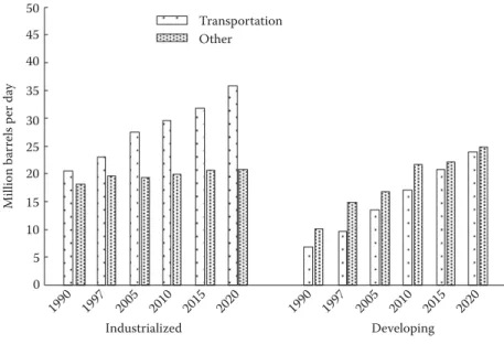
As shown inFigure 1.7, the transportation sector is the primary user of petroleum, con- suming 49% of the oil used in the world in 1997. The patterns of consumption of industrial- ized and developing countries are quite different, however. In the heat and power segments of the markets in industrialized countries, nonpetroleum energy sources were able to com- pete with and substitute for oil throughout the 1980s; by 1990, the oil consumption in other sectors was less than that in the transportation sector.
Most of the gains in worldwide oil use occur in the transportation sector. Of the total increase (11.4 million barrels per day) projected for industrialized countries from 1997 to 2020, 10.7 million barrels per day are attributed to the transportation sector, where few alter- natives are economical until late in the forecast.
In developing countries, the transportation sector also shows the fastest projected growth in petroleum consumption, promising to rise nearly to the level of nontransportation energy use by 2020. In the developing world, however, unlike in industrialized countries, oil use for purposes other than transportation is projected to contribute 42% of the total increase in petroleum consumption. The growth in nontransportation petroleum consumption in developing countries is caused in part by the substitution of petroleum products for non- commercial fuels (such as wood burning for home heating and cooking).
Improving the fuel economy of vehicles has a crucial impact on oil supply. So far, the most promising technologies are HEVs and fuel cell vehicles. Hybrid vehicles, using current IC engines as their primary power source and batteries/electric motor as the peaking power source, have a much higher operational efficiency than those powered by an IC engine alone. The hardware and software of this technology are almost ready for industrial manu- facturing. On the other hand, fuel cell vehicles, which are potentially more efficient and cleaner than HEVs, are still in the laboratory stage, and it will take a long time to overcome technical hurdles for commercialization.
Figure 1.8 shows the generalized annual fuel consumption of different development strategies of next-generation vehicles. Curve a–b–c represents the annual fuel consumption
1990 0 5 10 15 20
Million barrels per day
25 30 35 40 45
50 Transportation
Other
1997 2005 2010 2015 2020 1990 1997 2005 2010 2015 2020
Industrialized Developing
FIGURE 1.7
World oil consumption in transportation and other sectors.