Flood Model Report (RPS 2013)
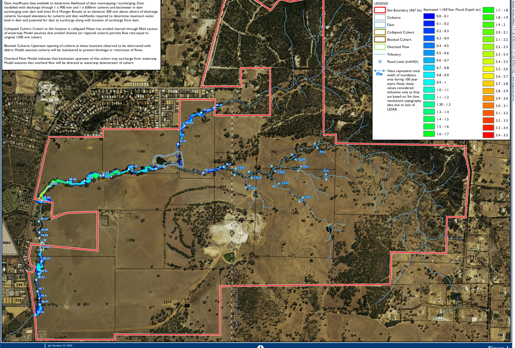
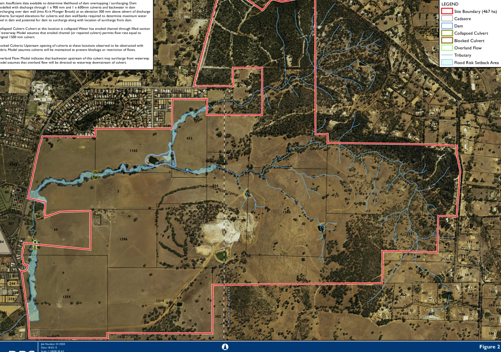
An assessment of flood levels and flood extent during a 1 in 100 year ARI event at Ki-it Monger Brook has been completed to assist in future development of the area. A total catchment area of approximately 5.2 km2 was estimated for the Ki-it Monger Stream upstream of the Great Northern Expressway.

Foreshore Area Report (RPS
REPORT
Bullsbrook Landholding
KI-IT MONGER BROOK FORESHORE AREA REPORT
The document may only be used for the purposes for which it was employed and in accordance with the Terms of Appointment for the commission.
SUMMARY
A CCW (UFI 12681) is associated with Ki-it Monger Brook in the south-west of the site, which is proposed to be incorporated into the surrounding POS. The topography of the site slopes down to the stream on both sides of Ki-it Monger Brook.
PLATES
APPENDICES
INTRODUCTION
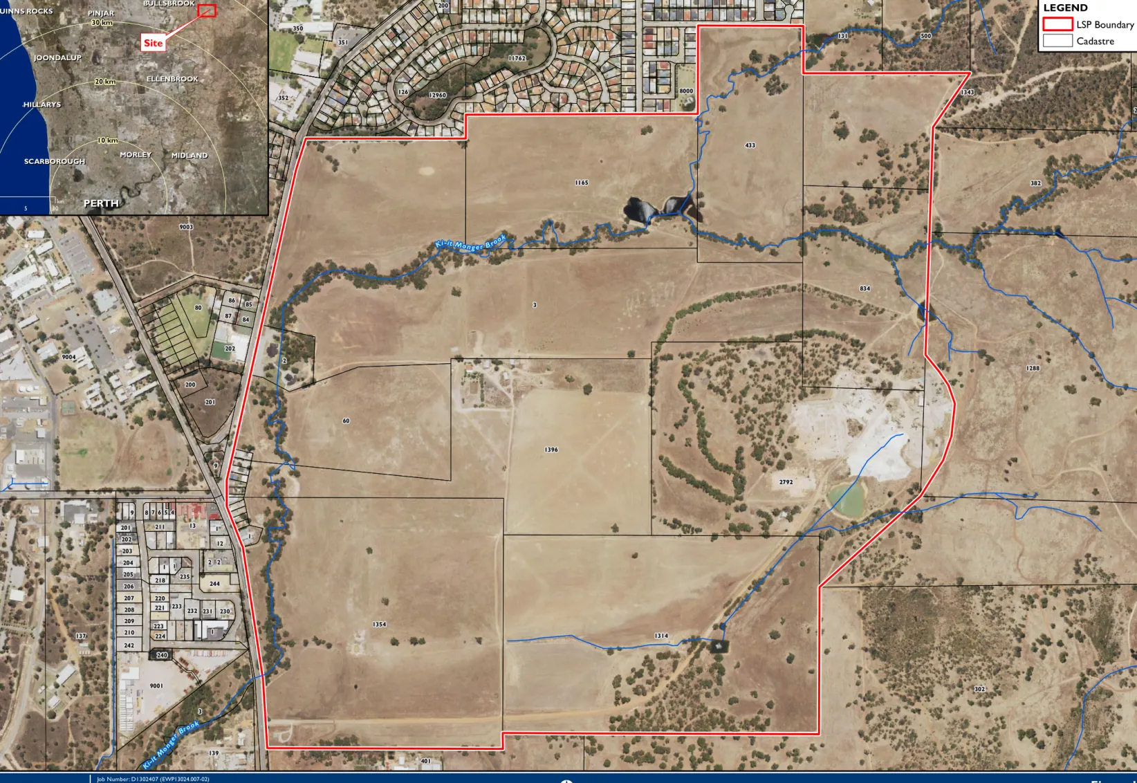
The existing site of Bullsbrook is located immediately north of the site, with agricultural land located to the south, and the site is bounded by the Great Northern Highway and Chittering Road to the west and Taylor Road to the east (Figure 1). The common lands (hereinafter referred to as the "Site") are proposed for residential and related uses, including the provision of residential, transitional and rural lifestyle residential lots in conjunction with primary schools, aged care facilities, commercial retail centers and district recreational facilities, local public open space (POS) and riparian reserve linked to the seasonal Ki-it Monger Brook. As part of the District's water management strategy prepared for the site, the then Department of Water (DoW) highlighted the requirement for a desktop biophysical assessment and riparian justification of the Ki-it Monger Brook in the riparian zone report.
A riparian assessment was also carried out in accordance with Operational Policy 4.3: Identification and Establishment of Waterway Coastal Areas (DoW 2012) and Designation of Coastal Reserves (Water and Rivers Commission 2001).
BIOPHYSICAL CRITERIA
Vegetation
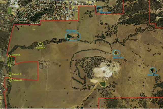
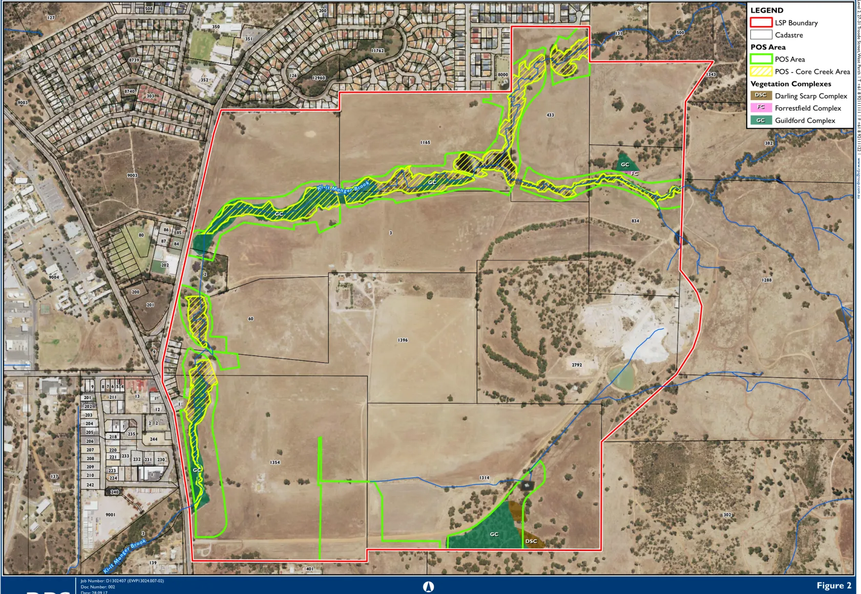
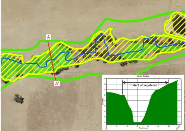
There are two wetlands that occur within parts of Ki-it Monger Brook; one is classified as a Conservation Category Wetland (CCW) (UFI 12681) and one is a Multiple Use Wetland. It was found that there were no differences in vegetation type, floristic composition, condition or values between the CCW section of Ki-it Monger Brook, the Multiple Use section or the unclassified section of the brook. The aerial images in Figure 2 confirm that the majority of native vegetation outside the channel has historically been cleared for agricultural purposes.
The maximum width of the remaining riparian vegetation is approximately 84 m (including both sides of the bank), but in most places it is significantly less. An example of a cross section illustrating the topography of the Ki-It Monger Brook channel banks (vertically exaggerated) and the extent of vegetation relative to the channel is illustrated in Figure A. A desktop search identified no significant flora species recorded or likely to occur along or near the stream line.
It is not listed by the Commonwealth Environment Protection and Biodiversity Conservation (EPBC) Act 1999 or listed in the Biodiversity Conservation Act 2016. No threatened flora, priority flora or other important plant species have been recorded in the study area.
Fauna Habitat
Soil Types
No test wells were dug within the creek line, but test wells were placed on either side of Ki-it Monger Brook. The findings of the geotechnical investigation were consistent with the environmental geology mapping, although there were also alluvial clay (and silt) deposits along the creek line. Apart from alluvial deposition around Ki-it Monger Brook, the soils did not move very differently from the brook, indicating that the vegetation type would not have varied significantly, and would probably have been the Er1 vegetation unit.
Erosion
Topography and Landforms
Hydrology
Heritage
Current and Proposed Land Use
The main purpose of the development drainage design for the site is to contain and treat runoff from the first 15mm of rainfall on site, which will be placed outside the Ki-it Monger Brook foreshore area, i.e. Further details on the drainage design for the location are discussed in the associated Local Water Management Strategy (this report is appended to the LWMS). Rehabilitation of the Ki-it Monger stream and the proposed landscape design of the surrounding POS will improve the ecological function of the waterway in its current state.
POS is proposed to surround the majority of the foreshore area, which will act as a buffer for the development. The POS will incorporate other features including biofiltration areas to retain and infiltrate development runoff from the 15mm rainfall event, dual use paths, park land for informal use and playground equipment. The incorporation of POS around the majority of Ki-it Monger Brook will facilitate and allow future residents to engage with the brook, increasing its social value and may also contribute to increased property values.
Emerge has prepared draft cross-sections that outline the proposed landscape plan for the POS surrounding the coastal area.
Southern Drainage Line
With the majority of the constructed agricultural drain cleared of native vegetation, it has no or very limited ecological value. The level 2 vegetation and flora survey mapped this agricultural drainage area as being in a 'totally degraded' state (Ecologia 2016). Test welling undertaken as part of the geotechnical investigation (Galt Geotechnics 2014) did not identify the soil type along this drainage line to be associated with a waterway, and was consistent with other test wells.
The section of drainage line that runs across Lot 1314 is significantly eroded as shown in Plate 5. As this drainage line is a constructed agricultural drainage that is not a tributary of Ki-it Monger Brook, the post-construction drainage plan for it is to be piped drainage system to POS with biological retention areas that retain and clean runoff from the first 15mm of rainfall.
ALIGNMENT OF THE FORESHORE AREA
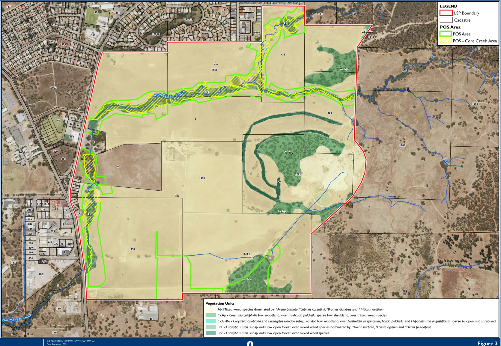
Ab: Mixed weeds dominated by *Avena barbata, *Lupinus cosentinii, *Bromus diandrus and *Triticum aestivum CcAp - Corymbia calophylla low forest, over +/-Acacia pulchella sparse low shrub, over mixed weeds. G2 - GRAVEL - strong brown, coarse, sub-rounded to rounded lateritized granite pebbles in clay-silt matrix moderately graded, of colluvial origin GR - GRANITE - mesocratic, fine to coarse grained, varies in composition from granodiorite to granite, adamellite being the most common variety. LA1 - LATERITE - solid and cemented, sometimes vesicular; up to 4 m thick, covered with a ferruginous gravel in a clay-sand matrix of residual origin.
Mgs1 - GRABBING LOOT - hard brown, fine to occasionally coarse-grained, sub-rounded quartz laterite silt, heavily weathered granite pebbles, some fine to medium-grained quartz sand, with alluvial or Msg - SILT SANDY - hard brown, hard, friable, partly dispersed, horizons with random pebbles with small matrix containing quartzite, quartz, granite, laterite, of colluvial origin. S6 - SAND - light gray, fine to coarse, angular to sub-rounded, quartz with some feldspar, moderately segregated, loose, colluvial in origin. laminated, occasionally micaceous ST2 - SAND NUT - Pale yellow to brown, fine to medium grained, quartz sand and feldspar in aromatic matrix.
LANDFILL
Local Structure Plan
- Water Corporation
- Water Corporation Correspondence
- Groundwater Licence
- Detailed Water Use Plan
Preference is given to the portion of the AMEX land north of the creek that will be constructed first (sites C and H). Alternative, temporary PS schemes specific to serving the district south of the creek (A, B, D, etc.) may be considered, but will depend on the capacity available in the city network to accept pumped streams. Acquisition of the proposed HL refueling site is nearing completion and the project has recently been activated.
Project scoping for the first 2.5ML HL storage will begin this year once we own the site. The existing tank will be the service tank for the existing LL/gravity zone tank for the foreseeable future and will also act as part of the handover arrangement up to the new HL tank. Substantial development of the land in question, particularly areas south of the creek and upland to the east, will likely require the longer term LL tank shown.
Our water planners have planned a review of the Bullsbrook scheme to start later this year.
Development Staging Plan
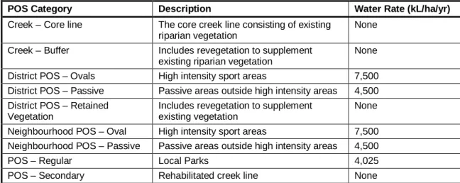
Core Creek Line Creek Buffer District POS - Ovals District POS - Passive POS District POS - Retained Vegetation Neighborhood POS - Oval.
Detailed Water Use Plan
Landscape Concept Plan
Drainage Catchment Plan
ORIGINAL SHEET SIZE A1
WARNING
1100DIAL BEFORE YOU DIG
BULLSBROOK
1 IN 10 YEAR PIT AND PIPE CATCHMENT PLAN
PANZICH
FOLEY
228,855SACRI CHURCH
POS - 7,479
Drainage Modelling
Drainage Modelling
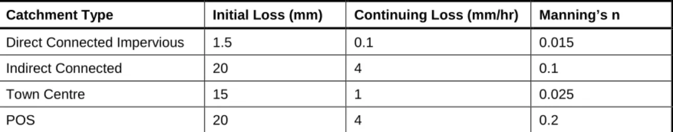
Directly connected catchments were defined in the model as impervious catchments connected to the drainage network. The post-development model determined that, assuming no stormwater retention or detention, the peak 1% AEP discharge rate for the critical (6 hour) event increases from 12 m3/s to 14 m3/s. The size of flood storage basins is based on an assessment of the POS areas and design surface levels to determine the most suitable areas for flood storage and the likely volumes that can be accommodated within the available POS.
The modeling then involved an iterative process to optimize the distribution and quantity of flood storage throughout the development and to confirm the required volumes of flood storage. The graph shows the discharge rate for all design storm durations (1 hour to 72 hours) for three scenarios; pre-development conditions, post-development conditions without any flood storage and post-development conditions with modeled flood storage included. The graph also shows that once the modeled flood deposits are included, the area's discharge rate is attenuated to pre-development conditions for all storm durations.
The drainage modeling results are provided in Table 13-D which includes the modeled basin sizes, volumes, flood areas, depths and preliminary size of the detention basin outlet pipes.