Performance Outcomes
District Plan Requirements
Building Code Requirements
External Standards
NZS 4058 Specification for precast concrete drainage and pressure and non-pressure pipes NZS 3109 Concrete construction. BS 3412 Methods of specifying general purpose PE materials for molding and extrusion NZS 3501 Specification for copper pipes for water, gas and sanitary purposes. AS/NZS 4020 Testing of products for use in contact with water AS/NZS 4087 Metallic flanges for waterworks purposes AS/NZS 4129 Fittings for PE pipes for pressure applications AS/NZS 4130 Polyethylene (PE) pipes for pressure applications.
AS 4181 Stainless steel clamps for water purposes AS/NZS 4331 Metal flanges – Part 2: Cast iron flanges. NZS 4442 Welded steel pipes and fittings for water, sewage and medium pressure gas NZS 4501 Code of practice for the location and marking of fire hydrants. NZS/BS 5163 Specification for predominantly key operated cast iron gate valves for waterworks purposes.
AS 3571/AS 3572 Glass Reinforced Plastic (GRP) Pipe Fittings and Fittings www.astt.com.au Australasian Society of Ductless Technology.
Reticulation Design
- General
- Capacity and Layout
- Structural Integrity
- Level of Service
- Design
- Permitted Head Losses
- Reservoir Head
- Normal Working Demand Flows
- Fire Fighting Demand Flows
- Alterations to Existing Infrastructure
- Depth of Water Mains
- Level of Service
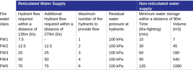
- Water Pressure and Storage Requirements
Any proposed water supply system (or extension of an existing water supply system) will be sufficient to meet these service levels at the time of design and for the reasonably foreseeable future. Minimum flow rate at each connection 30 liters per minute for design flow rates (see also Table 7-3) Minimum normal working residual pressure 300 kPa at the delivery point. Note: All lots and buildings equipped with their own on-site systems meet the requirements of the applicable Resource Management Plan (RMP).
Connections to the existing network will be undertaken by a contractor approved by Council, at the cost of the Developer. Similar provision shall be made to provide the specified cover on valve and hydrant shafts;. In the meter box or main rider valve, the pipe is allowed to have less cover where it is raised to match the mounting height.
Further specific reference to the requirements Code of Practice may be required for unusual situations. Note: See the Fire Fighting Code of Practice for additional notes and other specific requirements.
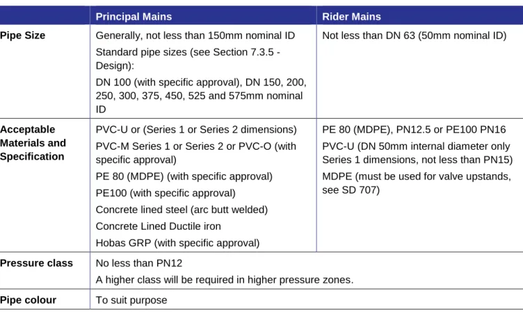
Pipe Specifications
- Pipe Size
- Pipe Materials
- Pipe Joints
- Unrestrained Mechanical Couplings
- PVC Pipe Joints
- PE Pipe Joints
- Welded Steel Pipe Joints
- Seismic Design for Pipes
- Watermains in Hydrocarbon Contaminated Ground
Whenever the outside diameter is shown on a drawing or specified, it will be indicated by "OD". The Council will assume that dimensions without 'ID' or 'OD' refer to the nominal inside diameter ('ID'). Installation will be in accordance with AS/NZS 2032 and AS/NZS 2566 Part 2, with particular emphasis on anchoring valves and hydrants against movement during operation.
Specially designed flexible joints shall be provided at all junctions between pipes and rigid structures (such as reservoirs, pumping stations, bridges and buildings) in natural or engineered soils. A geotechnical investigation will be used to assess the possibility of soil liquefaction under seismic loads and to assess the likely effects of liquefaction on the subsoil below the ground. The assessment will be carried out in accordance with the NZGS guidance: Guidance on the identification, assessment and mitigation of liquefaction hazards.
Fittings
- Pipe Fittings
- Corrosion Protection
- Hydrants
- Positioning of Valves
- Depth of Valves
- Sluice Valves
- Rider Main Valves
- Air Release Valves
- Scour Valves
- Butterfly Valves
- Non-Testable Non-Return Valves
- Valve Boxes
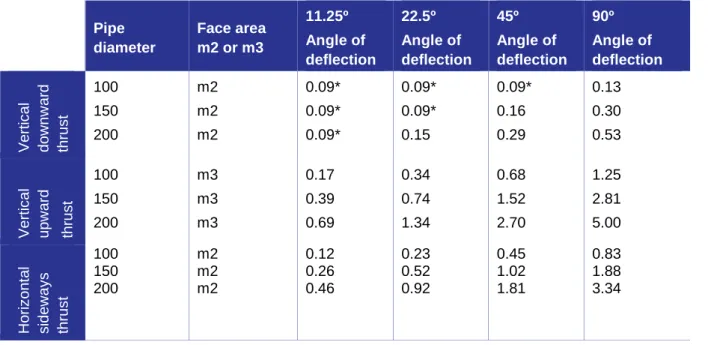
- Restraint blocks
- Thrust Block design
- Thrust Block Design Alternative
Ductile iron sockets for elastomeric sealing joints used with PVC pipe shall be of the "deep socket" type. Flanges made of steel, gray cast iron and nodular cast iron will be additionally protected by a sheathing system. For water mains over 200mm diameter line valves will be required at least every 450m and will be installed as agreed with the council.
They will be installed in such a way that ground water cannot enter the main at negative head pressure. Automatic air valves shall be flanged and mounted on flanged risers with an integral isolating valve accessible from ground level. Limiting block bearing area calculations shall be submitted with the engineering plans for checking and approval.
Water Supply Connections
- Point of supply to customer
- Service Connection Diameter
- Individual Connections
- Tapping Bands and Ferrules
- Meter Assembly for 20mm and 25mm ID Connection
- Meter Assembly for 32 - 40mm ID Connection
- Meter assembly for 50mm ID and larger Connection
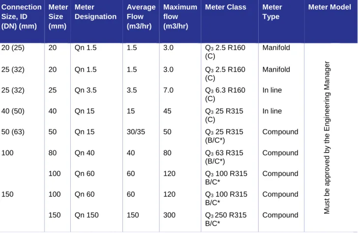
- Water Meters
- Backflow Preventers
- Reuse of Existing Service Connections
- Disconnections
- Fire Sprinkler Supply
- General
34;Talbot" Bronze push-fit swivel ring with the flow of water controlled by a screwed brass plug. Taper saddles shall not be used on PE pipe without approval by the Engineering Manager. For connections, larger than 50mm ID, the connection shall be by means of an extended gibault tee and sluice valve with the approval of the Engineering Manager.
Metal meter boxes shall be used for commercial and industrial entrances and in residential areas subject to heavy traffic and with the approval of the Engineering Manager. If a reduced pressure zone backflow preventer is used, it shall be mounted above ground level. Must be approved by the Engineering Manager. for composite meter; class B high flow meters, class C low flow meters;.
The applicant may be required to submit hydraulic calculations to support the choice of gauge size to Council for approval. The type and location of backflow preventers will be in accordance with the Building Act, Health Act 1956 as amended by the Health (Drinking Water) Amendment Act, AS/NZS 2845.1 and the Water Supply Council Regulation.
Pumping and Storage
- Pump Station Design
- Access and Services
- Electrical Equipment
- Commissioning
- Reservoir Requirements
- Security of Water Supply Facilities
- Private Pumping Stations
The site is to vest with the Council and will have a sealed access road for maintenance vehicles. The premises must have as a minimum screen planting on all common boundaries which will not be 2m high on the South boundary. All electrical equipment must be assembled and installed in accordance with these standards or the.
Electronic copies of the manual will be provided to Council upon handover of the completed pumping station and associated works. This commissioning will take place in the presence of a representative of the Council and the Council's operation and maintenance contractor. This may result in the Council working with the developer to optimize the reservoir design and location.
The developer is responsible for all costs associated with providing and installing locks.
Construction and Installation
- Trench Width
- Base of Excavation
- Trench Support
- Trench Foundation Stability
- Dewatering
- Metal Bedding
- Pipe Embedment
- Geotextiles
- Concrete Protection
- Water Stops and Trench Groundwater
- Pipe Installation
The base of the channel must be checked for soil stability by the DPA. If deposits in existing storm drains or pipes already in place occur as a result of the operations of the Developer or the Contractor, such deposits shall be promptly cleaned at the cost of the Developer or the Contractor as applicable. When choosing compaction equipment, the number of passes and the thickness of the layer to be compacted, the material to be compacted and the pipe to be installed will be taken into account.
Water traps and trench drainage will be constructed to prevent unwanted movement of groundwater along the trench and pipeline, see SD613 (Chapter 6). All captured stormwater must be routed to a storm sewer network or at least an approved storm drain. The inner walls of the pipe will be clean and free of all dirt, debris and water.
Trenchless Technology
- General
- Tracer Tape
- Tracer Tape Installation
- Tracer Wire
- Tape or Wire Testing
- Testing, Disinfection and Connection
- Trenching
Binding the ends of the tape together is not acceptable because the polythene coating prevents electrical conduction. All final test results sheets must be included in the as-built information package to be provided to the Council. Testing will be done on a case-by-case basis, depending on the size of the pipe network and the length of the pipe.
In the meter reading column, the reading only shows to the nearest whole cubic meter (BLACK NUMBERS on the meter). The Council operates low-flow rural water supplies outside urban centers across large parts of the Waimea and Moutere areas. Many of the pipelines (laid with the consent of the "then" owner) serving these schemes are not protected by easements, but cross large tracts of private land.
Connection to some of the schemes is limited by pipeline capacity, water permit conditions and allocation limits set out in the TRMP. When considering subdivision or development in rural areas, planners must first ascertain the existence of a networked water supply system in the area. Due to the lack of consistent rainfall in the Tasman area, roof water supply alone cannot be relied upon to service the . subdivision).
The supply location must be suitable for all weather conditions for a two-axle truck. These will be provided with access, reticulation (main pipe with a minimum diameter of 100 mm), fittings for fire-fighting purposes and a paved area reserved for fire extinguishers. The fire brigade couplings are located at a maximum of 90.0 meters from and a maximum of 6.0 meters at the house.