A soap film on a wire loop is a minimal surface given the limitations of the wire [Dier 92]. Any infinite strip of the two-dimensional Euclidean plane (E2) can be wrapped over the cylinder in such a way that it covers the surface. Details on the use of these gaskets in new materials can be found in [Lord 06].
By mapping the decorations in the universal TPMS coverage space (H2) to E3, we enable the reduction of complex (3D) Euclidean geometry to simpler (2D) hyperbolic geometry. Laying down a universal TPMS coating discretized with surface surface symmetries (instead of E3 symmetries) originates from the ideas of Sadoc and Char. We discuss each of the current methods in relation to these three structural elements.

Significant Results
A fruitful approach is to computationally constrain any given entanglement configuration to a minimum energy state. Further, another simulated annealing process with some additional measures imposed to remove the structure lock in the local minimum is given in [Grze 97]. It uses a repulsion mechanism to push away adjacent segments of the knot, along with a contraction mechanism to tighten the knot.
We get two such edge geometries for a net, one is the geometry of the tile edges as they sit on the TPMS, and the other is the ideal geometry found by simulation. An interesting consequence of the idealization of weaving into optimal configurations is the geometry of the filaments is often spiral. As a bio-material, this beautiful property of the idealΣ+ rod packing provides an explanation for the keratin organization in the corneocytes of the stratum corneum layer of the skin.
Overview of the thesis
An orbifold is the quotient of a manifold by a discrete group of isometries of the manifold [Do 80]. More specifically, it is a topological structure where all copies of the repeating pattern are "glued" under appropriate symmetries, so that the "unrolling" of the orbifold in any covering space results in a repeating pattern. Glide reflections, which involve a reflection and a translation of the motif along the mirror line, denoted by Conway symbol×.
The terminology of orbifolds is combined to form a string of the relevant symmetries of the form AB..C∗ab..c×..◦. This orbifold is a polygonal section of the plane (be it spherical, euclidean or hyperbolic) bounded by mirror boundaries. Geodesic paths passing through the center of the circle, such as m, are represented by straight lines.
Abstract topology of tilings: Delaney–Dress
Color the rooms so that those connected by tiling isometries have the same color. The triangulation consists of vertices placed at each of the tile faces, tile vertices, and tile edges. By ghosting a single edge of the conventional tiling shown in part (a), a free tile of H2results, which inherits the Delaney-Dress coding.
Identify an asymmetric orbifold domain of the free tiling; this is the domain of triangulation. All symmetry 'corners' of the tile boundary (intersections of mirror lines or centers of rotation) are occupied by 0 vertices. All symmetry 'vertices' in the interior of the tile with order >2 are occupied by 2-vertices.
All other symmetry 'corners' in the interior of the tile (those with order≤2) are occupied by ¯1–vertices. 1 – vertices at each of the∗2 mirror intersections in the interior of the tile and a 2-vertex in between. After removing a ¯1-vertex (and its associated edges), the neighboring 2-vertex slides to the location of the previous ¯1-vertex, preserving all other connections.
After removing a 0-vertex (and its associated edges), the neighboring 1-vertex slides to the location of the previous 0-vertex, preserving all other connections. We remove each of the ¯1–vertices, and examine the resulting encodings, as shown in Fig. The removal of this room, and the subsequent sliding of the 1–vertex gives a simpler encoding of the free tiling.
The upper encoding should not be further simplified, but the lower encoding can be simplified even further by removing the 0 vertex of degree 2.
Embedding orbifolds in the universal cover space
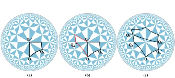
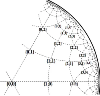
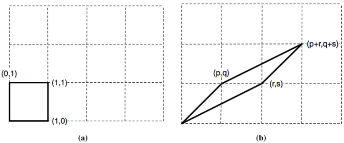
The corners of the square coincide with the points and{0,1}, establishing a reference frame of Z×Z for subsequent embeddings (b) Another embedding of 2222 relative to the established reference frame. A new presentation of the same symmetry group specifies the generators Q)T,Q)A,Q)Band QC) relative to the reference frame so that the group relations are preserved. We require that the only isometries of the parallelograms are the 2-fold rotations at the vertices, and that the enclosed area must be 1 (area equal to the square of the reference frame embedding), since all cuts of the orbifold must span the same area.
The other group relation, where Q)AQ)BQ)C must be equal to Q)T, is also satisfied by these elements (operation shown below), hence the generators Q)T,Q)A,Q)BandQC) have a presentation of the symmetry group of the 2222orbifold. Start by choosing an embedding of the orbifold as a reference frame in H2, designating four generators to present the symmetry group: QT, QA, QBandQC. Consider the quadrilateral formed by connecting the four generating elements of the group (fig.
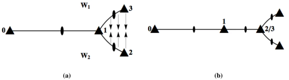
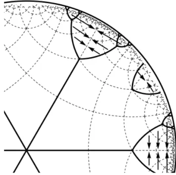
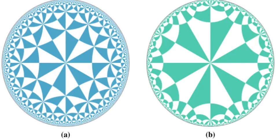
32 Free tilings of the hyperbolic plane .. if the quadrilateral is a valid representation of the group, we consider the group relations. To enumerate possible embeddings, we determine possible locations of the QC) generator relative to the reference frame: the analog of finding the coprime{p,q}vertex of the parallelogram. Of each geodesic ray from the origin (the end of which will be the location of QC), exactly three copies will be radiated from !1, one in each of sectors W1, W2, and W3. IfQC) (the end of the geodesic ray) is placed in sector W3, as shown by the blue geodesic in Fig.
Using the same argument in this new configuration, further W3 sectors of the plane can be excised and the boundary stitched, resulting in an infinite line of 2-fold rotations in an infinite plane. There are infinitely many forbidden sectors located at each 3-fold rotation of the discretization, with only three such sectors shown here. Reducing each 3-fold rotation of the discretization of H2 to a 2-fold rotation transforms the discret into the symmetry group 2222, so, from the orbifold cost formula, we are left with a discretization of E2.
The removal of sectors of the Hyperbolic plane and the subsequent sewing of the boundaries resulted in exactly a boundary-free Euclidean plane.
Embedded tilings commensurate with TPMS
In a regular ribbon tiling, 1-transition edges imply that the degree-3 vertex of the tiling boundary must have either 3-fold symmetry or ∗3 symmetry. The complement of the regular ribbon tiling on∗2223 interchanges the 0–vertex and 2–vertex locations of the triangulation as well as the 1–vertex and ¯1–vertex locations. The Delaney-Dress encoding of the complementary regular ribbon tiling of∗2223 is shown in Fig.
It is obtained by exchanging the 0-vertex and 2-vertex sites and the 1-vertex and ¯1-vertex sites of the regular ribbon tiles. The positions of the reference frame generators QT, QA, QB and QC in the ∗246 map are shown in Fig. Changing the boundary values for embedded regular ribbon tiles and complements leaves both decorations unchanged.
The remaining two∗2 crossings or 2-fold rotations define the plate translation symmetry of the infinite bar. The ornaments go from place∗4 of the orbifol, along the border of the mirror, to place∗2. The complement of a regular strip tiling in∗2224 inverts vertices 0 and 2 vertices of the Delaney-Dress triangle, as well as vertices 1 and ¯1.
The Delaney–Dress encoding of the complementary regular ribbon tiling of∗2224, known as the 123Ctiling, is shown in Fig. The reference frame embedding of the generators of the 2224orbifold in the∗246 tiling of H2 is set (Fig. The complement of the plain ribbon) tiling interchanges the infinite translation axis of the infinite ribbon tile with the boundary components of the tile.
The automorphism of orbifold2∗26 is a line of symmetry going from ∗2vertex to 2-fold rotation, mapping the ∗6site to the other∗6site in the embedding. 2.42(b,c) shows the two automorphic regular ribbon tilings of distinct geometry that arise from the embedding of the 122Rtiling (Fig. 2.40) into the ∗246 diagram of H2. 2.42(d,e) also shows the two automorphic complementary tilings given by the embedding of 122Ctiling (Fig. 2.41).
Lower Order Symmetry Groups
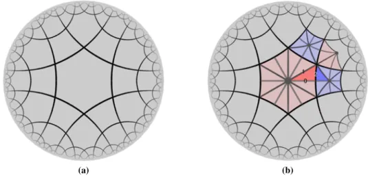
By choosing QC) from a particular set of 2-fold rotations, we indicate which set of 2-fold rotations will not be isometries of the 22222 embedding. There are thus three embeddings of the 22222orbifold with distinct generators, as described in [Robi 04a]. More generally, the 4-fold vertex in the example constructed can be any even number of rotations, so an equivalent construction will work for any 2222job-ifold.
Consider free tiles that are regular (1-transitive edges), and the infinite tiles are branched instead of ribbons. These branched tiling cause vertices in the complementary tiling, instead of infinite geodesic boundaries in the case of ribbon tiling, and we omit these complementary tiling. The only regular free tiling of the 22223 orbifold is shown in Fig. 2.51, with a single edge transitioning from the 3-fold rotation to the 2-fold rotation called QE.
To embed this orbifold in the ∗2226 tiling of H2, we choose parameters to form two Euclidean parallelograms with a common edge. The vertex QC) (the 2-fold rotation that will not be a generator of 22223) must be chosen as an image of QC (not an image of QA or QB). To ensure that the correct group is obtained, we restrict the position of QC) to be a coprime integer pair {p,q} where pi is even (or 0) and q is odd (this restriction ensures that the deleted 2-fold rotation is an image of QC ).
The geometry resulting from the embedding has an additional ∗22223 symmetry, and the decoration is equivalent to that built on the ∗22223orbifold and shown in the figure. The tile boundary consists of a single edge that runs from 3 times the rotation to Q )E. Thus, the free deployment depends only on the position of Q)E and remains unchanged for different choices of Q)A, Q)band Q)D.
Furthermore, by conjugations of the ∗2226 grid, we only need to consider coprime pairs in the positive-positive quadrant of Z×Z.