37 Annual Condensed Matter and Materials Meeting
Wagga 2013
Charles Sturt University, Wagga Wagga, NSW 5
thFebruary – 8
thFebruary, 2013
ISBN: 978-0-646-59459-0
2 Editorial Note
Proceedings of Wagga 2013
The 37th Annual Condensed Matter and Materials Meeting ISBN: 978-0-646-59459-0
Editors: Garry McIntyre and Richard Mole
The 37th Annual Condensed Matter and Materials Meeting was held at Charles Sturt University, Wagga Wagga, NSW from 5th – 8th February, 2013. There were 88 attendees, including international visitors from Singapore, Brazil, Turkey and Germany. A total of 11 invited and 18 contributed oral papers were presented during the two and one half days of scientific sessions. There were also two sessions with a total of 53 poster presentations. All presenters were invited to submit a manuscript for publication in the conference proceedings. Each manuscript was refereed by at least two anonymous reviewers who worked to a set of guidelines made available by the editors. Each accepted publication therefore satisfies the requirements for classification as a refereed conference publication (E1). The organizers would like to thank the 25 reviewers for their time and effort in reviewing manuscripts, which resulted in 14 papers being accepted for publication. The accepted manuscripts are available at the on-line publication section of the Australian Institute of Physics national web site (http://www.aip.org.au/).
Organising committee: Garry McIntyre, Richard Mole, Kate Picirillo, Gordon Thoroughgood and Anna Paradowska
May 2014
3
2013 OVERALL TIMETABLE
Tuesday 5 February
16:00 - Registration desk open 16:00 – 18:00 Conference bar open
18:00 – 19:30 Dinner
19:00 - Posters wp1-wp28 to be mounted 19:30 – 21:00 Wine, beer, and cheese tasting
Wednesday 6 February
07:30 – 08:30 Breakfast
09:00 – 09:10 Conference opening
09:10 – 10:30 Oral Session: Papers wo1-wo3
10:30 – 11:00 Morning tea
11:00 – 12:30 Oral Session: Papers wo4-wo7
12:30 – 14:00 Lunch
14:00 – 14:50 Oral Session: Papers wo9, tp3 14:50 – 15:30 Poster Clips: wp1-wp28
15:30 – 16:00 Afternoon Tea
16:00 – 18:00 Poster Session: Papers wp1-wp28 18:00 - Posters: tp1-tp25 to be mounted 16:30 – 18:00 Conference bar open 18:30 – 22:00 Conference Dinner
Thursday 7 February
07:30 – 08:30 Breakfast
09:00 – 10:30 Oral Session: Papers to1-to4
10:30 – 11:00 Morning tea
11:00 – 12:30 Oral Session: Papers wo8, to6-to8
12:30 – 14:00 Lunch
14:00 – 15:00 Oral Session: Papers to9-to10 15:00 – 15:30 Poster Clips: tp1-tp25
15:30 – 16:00 Afternoon Tea
16:00 – 18:00 Poster Session: tp1-tp25 16:30 – 18:00 Conference bar open
18:00 – 19:30 Dinner
19:30 – 22:00 Trivia Quiz (Lindsay Davis Cup) Friday 8 February
07:30 – 08:30 Breakfast
09:00 – 10:30 Oral Session: Papers fo1-fo4
10:30 – 11:00 Morning tea
11:00 – 12:20 Oral Session: Papers fo5-fo7 12:20 – 12:40 Presentations and Closing
12:40 – 14:00 Lunch
4
2013 PROGRAM
Tuesday 5 February
16:00 - Registration desk open 16:00 – 18:00 Conference bar open 18:00 – 19:30 Dinner
19:30 – 21:00 Wine, beer, and cheese tasting
Wednesday 6 February
09:00 – 09:10 Opening: Garry McIntyre, ANSTO
09:10 – 10:30 Chairperson: Stephen Collocott, CSIRO Lindfield
09:10 – 09:40 wo1 Magnetic Structures of Rare-Earth Intermetallics: A two-pronged Attack Featuring Neutron Diffraction and Rare-Earth Mössbauer Spectroscopy
Seán Cadogan, UNSW Canberra INVITED
09:40 – 10:00 wo2 Optical Investigation of the Magnetoelectric Coupling via Phonons and Electromagnons in Multiferroics
Pauline Rovillain, UNSW Kensington/ANSTO
10:00 – 10:30 wo3 Coupling Between Electronic and Lattice Degrees of Freedom in 4f- Electron Systems Investigated by Inelastic Neutron Scattering
Michael Loewenhaupt, IFP Dresden INVITED
10:30 – 11:00 Morning tea
11:00 – 12:30 Chairperson: Jeff Sellar, Monash University
11:00 – 11:30 wo4 Atomic Scale Modelling for Real Nuclear Engineering Problems and Applications
Simon Middleburgh, ANSTO INVITED
11:30 – 11:50 wo5 Measuring Homogeniety of Metallic Glasses Using Novel Scanning/Transmission Electron Microscopy Techniques Amelia Liu, Monash University
11:50 – 12:10 wo6 Micron Resolution Strain Spectroscopy of a Rare-Earth Ion Doped Crystal
John Bartholomew, Australian National University 12:10 – 12.30 wo7 A One-Dimensional Spin-Orbit Interferometer
Tommy Li, UNSW Kensington 12:30 – 14.00 Lunch
14:00 – 15:40 Chairperson: Roger Lewis, University of Wollongong
14:00 – 14:30 wo8 High Resolution Dynamic Imaging at the Australian Synchrotron Daniel Häusermann, Australian Synchrotron INVITED 14:30 – 14:50 wo9 Element Specific and Depth-Resolved Interface Magnetism in
BiFeO3/La0.67Sr0.33MnO3 Thin Films Joel Bertinshaw, UNSW Kensington
14:50 – 15:10 wo10 Quantum Molecular Dynamics Simulation of Newly Developed Magnesium Based Bulk Metallic Glasses
Reza Mahjoub, UNSW Kensington
15:10 – 15:40 Poster Advertisement wp1-wp28: selected 2 minute talks
5 15:40 – 16:00 Afternoon Tea
16:00 – 18:00 Poster Session: wp1-wp28
18:30 – 22:00 Conference Dinner
wo11 The Higgs Boson at the Large Hadron Collider
Sara Diglio, University of Melbourne INVITED
Thursday 7 February
09:00 – 10:30 Chairperson: Chris Ling, University of Sydney
09:00 – 09:30 to1 Power Generation in Remote Areas Using Concentrated Solar Thermal and Hydrogen
Craig Buckley, Curtin University INVITED
09:30 – 09:50 to2 A Novel Multi-Scale Modelling Approach for Determining the Bulk Properties of Difficult-to-Characterise Composites
Paul Mignone, University of Melbourne
09:50 – 10:10 to3 MD Simulation and Experimental INS: A Marriage in Atomic Dynamics
Elvis Shoko, ANSTO
10:10 – 10:30 to4 The Search for Optically Addressable Single Spins in the Solid State:
Lessons Learnt from the NV Colour Centre in Diamond Marcus Doherty, ANU
10:30 – 11:00 Morning tea
11:00 – 12:30 Chairperson: Richard Mole, ANSTO
11:00 – 11:30 to5 Graphene and Topological Insulators: In What Ways Are the Transport Propoerties Different from Other Two Dimensional Electron Gases
Shaffique Adam, Yale-NUS College, Singapore INVITED 11:30 – 11:50 to6 Effect of External Electric Field on the Application of Graphene
Zhimin Ao, UNSW Kensington
11:50 – 12:10 to7 Haldane-Like Models in Buckled Lattices Anthony Wright, University of Queensland
12:10 – 12:30 to8 Time Resolved Magnetic Depth Profiles of a Thin Film Using Polarized Neutron Reflectometry
David Cortie, University of Wollongong 12:30 – 14.00 Lunch
14:00 – 15:40 Chairperson: Oleg Sushkov, UNSW
14:00 – 14:30 to9 Transforming Carbon Onions into Nanodiamond: a New Pathway to sp3 Carbon with Astrophysical Implications
Nigel Marks, Curtin University INVITED
14:30 – 14:50 to10 Magnetic Neutron Scattering on Nanomagnets: Decrypting Cross- Section Images Using Micromagnetic Simulations
Andreas Michel, University of Luxembourg 14:50 – 15.10 to11 Ferromagnetism in Teflon
Jiabao Yi, UNSW Kensington
15:10 – 15:40 Poster Advertisement tp1-tp25: selected 2 minute talks 15:40 – 16:00 Afternoon Tea
6 16:00 – 18:00 Poster Session: tp1-tp25
18:00 – 19:30 Dinner
19:30 – 22:00 Trivia Quiz, Conference Centre
Quizmaster: Trevor Finlayson, University of Melbourne
Friday 8 February
09:00 – 10:30 Chairperson: Lou Vance, ANSTO 09:00 – 09:30 fo1 Polyamorphism: Fact or Fiction?
Simon Clark, Macquarie University and ANSTO INVITED 09:30 – 09:50 fo2 Novel Block Co-polymer of DGEBA and Poly(trimethylene
terephthalate): Preparation, Characterization and Properties Sarath Chandran, Mahatma Gandhi University, Kottayam, India
09:50 – 10:10 fo3 Effects of Strain on the Electronic Properties of InAs/GaAs Core/Shell Nanowires: First Principles Study
Quanguo Jiang, UNSW Kensington
10:10 – 10:30 fo4 Exchange Bias in Neutron Irradiated Concentrated CuMn Spin Glass Lester Barnsley, Griffith University
10:30 – 11:00 Morning tea
11:00 – 12:20 Chairperson: Stewart Campbell, UNSW Canberra
11:00 – 11:30 fo5 What’s so Exciting about Low Dimensional, Magnetic Copper Oxides?
Kirrily Rule, ANSTO INVITED
11:30 – 11:50 fo6 Spin Gap Evolution upon Ca Doping in the Spin Ladder Superconductor System Sr14-xCaxCu24O41
Guochu Deng, ANSTO
11:50 – 12:20 fo7 Magnetism and Magnetic Structure of TbNiAl4
Wayne Hutchison, UNSW Canberra INVITED
12:20 – 12:40 Awards and Closing:
Glen Stewart, UNSW Canberra, and Garry McIntyre, ANSTO 12:40 – 14:00 Lunch
7
2013 POSTER SESSION: Wednesday 6 February
Theory, modeling, simulation
wp1 Detecting Artificial Graphene in GaAs Heterostructures S. Bladwell and O.P. Sushkov
wp2 Modeling of Electrostatic Potential on Artificial Graphene Z.-L. Cai and O.P. Sushkov
wp3 Dynamic Phase Transitions in the Spin-1 Blume-Capel Model under an Oscillating Magnetic Field within the Path Probability Method*
M. Ertaş and M. Keskin
wp4 Phase Diagrams of Spin S=1 Bilinear-Biquadratic Heisenberg Models C.J. Hamer and J. Oitmaa
wp5 Skyrmion Liquid and Skyrmion Glass in the Spin Spiral State of Underdoped Cuprates R. Kumar and O.P. Sushkov
wp6 The Energy Cost of Measurement for a Specific Curie-Weiss Model D.J. Miller
wp7 Domain Wall Functionality in Complex Oxides J.Seidel
wp8 Chemical Bonding in Aluminium: Comparison between QCBED and DFT A.E. Smith, P.N.H. Nakashima, and B.C. Muddle
wp9 Topological Insulating States in Ordinary Semiconductors O.P. Sushkov and A. H. Castro Neto
wp10 Using Quantum Magnetic Oscillations to Observe the ‘Topological’ in Topological Insulators
A.R. Wright and R.H. McKenzie
Magnetism (transition metal, rare-earth, actinide)
wp11 The Effect of Dy on the Time Dependent Behaviour of the Magnetization in Nd60–xFe30Al10Dyx, x = 0 to 4, Bulk Amorphous Ferromagnets
S.J. Collocott, X.H. Tan, and H. Xu
wp12 Magnetoelectric Coupling in TbMnO3 Explored via Raman Spectroscopy P.J. Graham, M. Bartkowiak, P. Rovillain, A.M. Mulders, M. Yethiraj, E. Pomjakushina, K. Conder, M. Kenzelmann, and C. Ulrich
wp13 Giant Magnetoelasticity at a Spin Gap Transition in the 5d Oxide Ba3BiIr2O9 C.D. Ling, W. Miiller, B.J. Kennedy, and M. Avdeev
8
wp14 Magnetic Properties and Magnetocaloric Effect in Layered NdMn1.7V0.3Si2
M.F. Md Din, J.L. Wang, R. Zeng, W.D. Hutchison, M.Avdeev, S.J. Kennedy, and S. X. Dou
wp15 18O Isotope Substitution on the Multiferroic Compound DyMnO3
N. Narayanan, F. Li, W.D. Hutchison, N. Reynolds, P. Rovillain, C. Ulrich, J. Hester, G.J. McIntyre, and A.M. Mulders
wp16 Thermodynamic Properties of an Anisotropic Heisenberg Model for the XY Pyrochlore Er2Ti2O7
J. Oitmaa and R.R.P. Singh
wp17 The Effect of Fe and Ni Substitution in Magnetocaloric MnCoGe
Q. Ren, W.D. Hutchison, J.L. Wang, W. Kemp, J.M. Cadogan, and S.J. Campbell wp18 Investigations into the Magnetic and Crystal Field Excitations of the Orthorhombically
Distorted Perovskites RVO3 (R=Dy, Tb, Pr, Ce)
N. Reynolds, P. Rovillain, S. Danilkin, K. Schmalzl, M. Reehuis, S. Miyasaka, F. Fujioka, Y. Tokura, B. Keimer, G.J. McIntyre, and C. Ulrich
wp19 Magnetic Order and Spin-Reorientations in RGa (R = Dy, Ho and Er) Intermetallic Compounds
R.A. Susilo, J.M. Cadogan, D.H. Ryan, N.R. Lee-Hone, R. Cobas, S. Muñoz-Pérez, B.
Rosendahl-Hansen, and M. Avdeev wp20 Spin-Reorientation in GdGa
R.A. Susilo, J.M. Cadogan, D.H. Ryan, N.R. Lee-Hone, R. Cobas, and S. Muñoz- Pérez
wp21 Structure and Properties of New Technetium Compounds
G.J. Thorogood, B.J. Kennedy, M. Avdeev, J. Ting, Z. Zhang, and G.R. Lumpkin wp22 Magnetic Properties and Magnetocaloric Effect in Mn0.9Ti0.1CoGe
J.L. Wang, P. Shamba, W.D. Hutchison, M.F. Md Din, M. Avdeev, S.J. Kennedy, S.J. Campbell, R. Zeng, and S.X. Dou
Nanoscience (nanomaterials, spintronics, molecular magnetism) wp23 Black Hydrogenated Titanium Dioxide
P. Imperia, R. Aldus, N. Booth, J. Muir, V. Jovic, and G. Waterhouse
wp24 Magnetic Properties of 3d Metal Nanoparticles Formed in SiO2 via Ion Implantation A.E. Malik, W.D. Hutchison, K. Nishimura, and R.G. Elliman
wp25 Explorations into the Electron-Phonon Interactions of the NV Colour Centre in Diamond
N.B. Manson and M.W. Doherty
9
wp26 ZnO/Ti-Compound Nanocomposites Prepared by Polyol Method A. Murador Filho, D.I. dos Santos, J.G. Kim, D.Q. Shi, and S.X. Dou wp27 Long-Range Transfer of Electron–Phonon Coupling in Oxide Superlattices
C. Ulrich, A.N. Driza, S. Blanco-Canosa, M. Bakr,, S. Soltan, M. Khalid, L. Mustafa, K. Kawashima, G. Christiani, H.-U. Habermeier, G. Khaliullin, M. Le Tacon, and B.
Keimer
wp28 Controlled Synthesis of Nanocrystalline BaFCl:Sm3+ X-ray Storage Phosphor X. Wang and H. Riesen
10
2013 POSTER SESSION: Thursday 7 February
Surfaces and interfaces
tp1 Analysis of Varied Richardson Constant Based on Numerical Device Model in Organic Light Emitting Diodes (OLEDs)
T. Hirai, K. Weber, J. O’Connell, M. Bown, and K. Ueno
tp2 Electron Self-Energy Variation from Rydberg Surface-State Resonances on Cu(110) M.N. Read
tp3 Wettability and Electrical Conductivity Switching in UV Irradiated Graphene Films Z. Xu, Z. Ao, D. Chu, and S. Li
Materials, engineering
tp4 Biomimetic Structure Design from Wood with Epoxy-Silica Composites N. Daud and R.A. Shanks
tp5 In Scotch Whisky, Where Are the Fe3+ and Cu2+ Ions (EPR Detected) Formed?
S. Drew and G.J. Troup tp6 Whither Wagga?
T.R. Finlayson and G.A. Stewart
tp7 Investigation of Residual Stresses in Aluminothermic Rail Welds B. Khodabakhshi, A.M. Paradowska, P. Mutton, and R. Ibrahim
tp8 Residual Stresses in High Strength Steel Tubes for Large Scale Infrastructure F.R. Mashiri, A.M. Paradowska, M. Khan, B. Uy, and Z. Tao
tp9 Non-Isothermal Crystallization Kinetics of Poly(lactic Acid)-Hemp Nanocomposites Plasticized with Tributyl Citrate
I.R. Mustapa, S. Chandran, R.A. Shanks, and I. Kong
tp10 Point Defect Engineering Strategies to Retard Phosphorous Diffusion in Germanium H.A. Tahini, A. Chroneos, R.W. Grimes, U. Schwingenschlogel, and H. Bracht tp11 U Valences and Site Occupancies in Doped Gd2Zr2O7 Pyrochlore-Structured Nuclear
Ceramics
E.R. Vance, D.J. Gregg, P. Gaugliardo, Y. Zhang, Z. Zhang, I. Karatchevtseva, G. Griffiths, J. Davis, G.R. Lumpkin, and G. Triani
Measurement techniques, instrumentation
tp12 An Alternative Recoil Implantation of the 100Pd/100Rh TDPAC Probe with Suppression of Elastically Scattered Projectiles
A.A. Abiona, W. Kemp, E. Williams, and H. Timmers
11
tp13 Epitaxial thin films of La0.85Ag0.15MnO3 produced by Polymer Assisted Deposition R. Cobas, S. Muñoz-Pérez,J.M. Cadogan,W.D.Hutchison, M.C. Ridgway, T. Puig, and X. Obradors
tp14 Time Resolved Magnetic Depth Profiles of a Thin Film Using Polarized Neutron Reflectometry
D.L. Cortie, X.L. Wang, K.-W. Lin, F. Klose, and A. Nelson
tp15 Attenuation and Multiple-Scattering Correction to a Neutron Time-of-Flight In-Situ Study
M.T. Crossley, E.MacA. Gray, C.J. Webb, and R.L. Smith
tp16 Commissioning of Polarised 3He Based Neutron Polarisers and Analysers on OPAL Instruments
W.T. Lee, T. D’Adam, F. Klose, D. Jullien, K.H. Andersen, K.C. Rule, A.J. Studer, and S. Danilkin
tp17 On the AFNMR & NQR Signal Enhancement via Population Transfer J.A. Lehmann-Horn and D.G. Miljak
tp18 Low Temperature THz Spectroscopy of 2, 4-dinitrotoluene L.M. Lepodise and R. A. Lewis
tp19 Terahertz Emission From Lateral and Sideways Photo-Dember Effects J. Mabon, K. Radhanpura, and R. A. Lewis
tp20 Neutron Laue Diffraction from Spin-Polarised Protons
G.J. McIntyre, M. Karlsson, F. Piegsa, B. van den Brandt, P. Hautle, T. Konter, O. Zimmer, E.M. Forgan, and C.J. Carlile
tp21 Pelican: An Inelastic Neutron Scattering Spectrometer With Polarization Analysis R.A. Mole and D. Yu
tp22 Effect of Heavy Noble Gas Ion Irradiation on Terahertz Emission Efficiency of InP (100) and (111) Crystal Planes
K. Radhanpura and R. A. Lewis
tp23 Recent Developments for Taipan at ANSTO
K.C. Rule, S. Danilkin, A.P.J. Stampfl, and W.T Lee
tp24 A Be-Filter-Based Neutron Spectrometer for Vibrational Spectroscopy
A.P.J. Stampfl, A. Chellappah, K.C. Rule, S. Danilkin, G.J. Kearley, and J.A. Stride tp25 Exploiting Fitted Electric Field Gradient Parameters: Axis Ambiguity and the
Asymmetry Parameter Constraint, 0 < η < 1 G.A. Stewart
12
Papers:
1. (wp4) The S = 1 Bilinear Biquadratic Spin Model on the Square Lattice: A Series Expansion Study
J. Oitmaa and C.J. Hamer
2. (fo4) Asymmetric Magnetization Reversal from a Cluster/Spin Glass Model L.C. Barnsley, E.MacA. Gray and C.J. Webb
3. (tp4) Biomimetic Structure Design from Wood with Epoxy–Silica Composites N. Daud and R.A. Shanks
4. (fo2) Poly(trimethylene terephthalate) Block Co-polymer with Epoxy Resin:
Preparation, Characterization and Properties Sarath Chandran, S. Thomas, R. A. Shanks
5. (tp9) Non-isothermal Crystallization of Poly(lactic acid)-Hemp-Silica Nanocomposites Plasticized with Tributyl Citrate
I.R. Mustapa, S. Chandran, R.A. Shanks and I. Kong
6. (tp2) Electron Self-energy Variation from Rydberg Surface-state Resonances on Cu(110) surface
M. N. Read
7. (wp28) Controlled Synthesis of Nanocrystalline BaFCl:Sm3+ X-ray Storage Phosphor Xianglei Wang, Hans Riesen
8. (tp3) Si Doping Induced Hydrophobic to Hydrophilic Transition on Graphene: a First Principles Study
Q. G. Jiang, Z. M. Ao, S. Li
9. (fo3) A New Preparation Method to Significantly Improve the Photocatalytic Activity of ZnO Nanoparticles
Z.M. Xu, J. Lu, Z.M. Ao, and S. Li
10. (tp25) Exploiting Fitted Electric Field Gradient Parameters: Axis Ambiguity and the Asymmetry Parameter Constraint, 0 ≤ η ≤ 1
G.A. Stewart
13
11. (tp5) In Scotch Whisky, From Where are the Fe3+ and Cu2+ Ions Sourced?
Simon C. Drew, Blaine Roberts and G.J.Troup
12. (to2) A Novel Multi-scale Modelling Approach for Determining the Bulk Properties of Difficult-to-Characterise Composites
P.J. Mignone, M. Wang, T.R. Finlayson, M.P. Echlin, A. Mottura, T.M. Pollock, D.P.
Riley, G.V. Franks
13. (wp17) The Effect of Fe and Ni Substitution in Magnetocaloric MnCoGe
Q. Y. Ren, W. D. Hutchison, J. L. Wang, W. Kemp, R. Cobas, J. M. Cadogan and S. J.
Campbell
14. (to6) Effect of External Electric Field on the Application of Graphene Z. M. Ao, Q. G. Jiang, and S. Li
14
The S = 1 Bilinear Biquadratic Spin Model on the Square Lattice: A Series Expansion Study
J. Oitmaa and C.J. Hamer
School of Physics, The University of New South Wales, Sydney 2052, Australia.
We use extensive series expansions at T = 0 to investigate the phase diagram of a spin-1 Hamiltonian on the square lattice. The model includes bilinear and biquadratic interactions (the 'J-K' model) and has been studied recently using a variety of other methods. We find a clear indication of the three-sublattice order conjectured recently via indirect arguments. We also compute the energy and order parameter in the quadrupolar phases.
1. Introduction
There has been considerable interest recently in spin-1 Heisenberg models with both bilinear and biquadratic nearest-neighbour exchange terms. The generic Hamiltonian, which we refer to hereafter as the 'J-K ' model, is
H = J Σ S
i. S
j+ K Σ (S
i. S
i)
2<i,j> <I,j>
The exchange parameters J, K may have either sign, and are often parametrized by J = cos θ, K = sin θ.
Studies of this Hamiltonian go back at least to the 1960s [1,2]. The mean-field phase diagram was discussed by Chen and Levy [2], where phases of both dipolar and quadrupolar nature were identified, and a more detailed discussion was given by Papanicolaou on the basis of semiclassical ‘flavour-wave’ theory [3]. More recently, the model on the triangular lattice was invoked to explain unusual properties of the material NiGe2S[4-7], and the presence of significant biquadratic exchange (with K < 0) in the iron pnictides has been suggested [8].
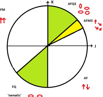
In the present paper we consider the model defined above on the two-dimensional square lattice. For K = 0, and by continuity for |K| << |J|, we expect a normal collinear ferromagnetic or antiferromagnetic (Néel) phase for J < 0, J > 0 respectively. In other regions of the phase diagram, phases with quadrupolar order, ferroquadrupolar (FQ) or antiferroquadrupolar (AFQ), may occur. Another feature of this Hamiltonian is the existence of special points (θ = π/4, -3π/4, ± π), where the spin symmetry group is enlarged from O(3) to U(3) [3].
In Figure 1 we show a schematic phase diagram, based on the flavour-wave theory of Papanicolaou [3], confirmed by Quantum Monte Carlo (QMC) studies [9,10] for K < 0, and a more recent study by Toth et al. [11] combining flavour-wave theory with numerical exact diagonalization. The phase structure is firmly established in the lower half of the phase diagram, where QMC calculations are valid, but not in the upper half, since QMC calculations suffer from a minus sign problem for K > 0. The most interesting quadrant is the region 0 < θ
< ππππ/2. Toth et al. [11] find a 3-sublattice AFQ phase (termed ’AFQ3') to be stable throughout the region ππππ/4 < θ < ππππ/2. Their approach becomes less certain below θ = ππππ/4, but they argue, by continuity, that a three-sublattice antiferromagnetic phase will be the preferred ground state in a finite window below θ = πππ/4. This is the conjectured AFM3 phase illustrated in Fig. π 1, in which the spins
15
Fig. 1 Phase diagram as a function of angle θ. Key: FM: ferromagnetic; AF: antiferromagnetic; FQ:
ferroquadrupolar; AFQ3: antiferroquadrupolar with 3-sublattice order; AFM3: antiferromagnetic, with 3- sublattice order.
are coplanar with a 1200 angle between spins on successive diagonal sublattices.
The initial motivation for the present work was to find more direct evidence for the AFM3 phase, and to locate the position of the boundary between the AFM3 and Néel phases.
At the same time we also obtain independent estimates of both the ground state energy and quadrupole moment in the quadrupolar phases. Given the inherent uncertainty in analytic approaches to S = 1 systems, it is important to test such results by other methods.
2. Method
In our calculations, we employ the method of linked cluster perturbation expansions [12], in which the Hamiltonian is written as
H = H0 + λ V
and series are obtained for various quantities, such as ground state energy and order parameters, in powers of λλλλ up to some order (typically 10-15). A basis is chosen in each phase, usually consisting of simple product states, where the ground state possesses the expected order in that phase. The unperturbed Hamiltonian H0 then contains all the diagonal terms in that basis, and the perturbation V all the off-diagonal ones, so that the physical Hamiltonian corresponds to λλλλ = = = = 1. . . . The series are analysed by standard methods (usually direct or Dlog Pade approximants), and evaluated at λλλλ = 1. The unperturbed ground state is expected to be adiabatically connected to the true many-body ground state of the full Hamiltonian H. It is possible to check this by testing for a singularity with λλλλ < 1 in the series. The method has been used successfully in many previous studies, including our previous work [13] on a spin- 1 model with single-ion anisotropy.
The calculation then proceeds along standard lines [12], with series for a sequence of finite clusters of increasing size combined to give series for the bulk system in the thermodynamic limit. We have used a total of 23937 clusters with 14 or fewer sites, which yields series for the ground state energy per site E0(λλλλ), the magnetization M(λλλλ) = <Szi> and
16
Fig.2. (a) Ground state energy per site from expansions in the Néel phase (black squares) and the AFM3 phase (blue circles). Dashed line: flavour-wave prediction; (b) Estimates of the magnetization in the Néel phase.
Dashed line: flavour-wave prediction; solid line: a fit to the data.
the quantity Q = <(Szi)2>, which is related to the quadrupole moment, to order λλλλ15. The series data are too extensive to reproduce here, but can be supplied on request. The results are discussed below.
3. Results
3.1 The Néel and AFM3 phases
We now turn to the results. In Fig. 2(a) we show the ground state energy per site, as a function of θ, from series in both the Néel and AFM3 phases. It can be seen that the Néel energy is the lower at small θ, until the AFM3 energy crosses over to become the lower at a transition point which we estimate around θ = 360. This is in good agreement with the estimates of Toth et al [11]. The flavour-wave estimate of the Néel energy is in extremely good agreement with the series results.
Figure 2(b) shows our estimates of the magnetization as a function of θ. It can be seen that the flavour-wave estimate is again very accurate at small θ. A fit to the simple form Mz ~ a(θc - θ)β to the data over the range 15 < θ < 30 degrees predicts that the magnetization vanishes at about θ = 310, with a very small exponent β ∼ 0.1. Even including the uncertain point at 350 in the fit gives a transition point near but below θ = 350.
The transition from one ordered state to a state with different order is generally expected to be 1st order. From the data above, the transition between the Néel and AFM3 phases looks more like a 2nd order transition. If it is a 1st order transition, it must be a very weak one.
Another possibility might be the existence of intermediate (spiral?) phases. We do not explore that possibility further here.
3.2 The AFQ3 Quadrupolar Phase
In the region πππ/4 < π θ < ππππ/2, Toth et al [11] propose a 3-sublattice antiferroquadrupolar (AFQ3) phase. Our series results for the ground state energy per site and quadrupolar moment Q in this region are shown in Figs. 3(a) and 3(b), respectively. As can be seen from Fig. 3(a), our series results for the ground state energy are in excellent agreement with those of Toth et al in this region, and join on smoothly to those for the AFM3 phase. This argues for a 2nd order transition between the AFM3 and AFQ3 phases, presumably fixed at θ = 450 by the higher symmetry obtaining there, where the dipolar AFM3 order parameter vanishes. Our
17
Fig.3. (a) Ground state energy per site from expansions in the AFQ3 phase (green squares) and the AFM3 phase (blue circles). Dashed line: flavour-wave prediction (Toth et al [11]; (b) Estimates of the quadrupole order
parameter Q in the AFQ3 phase.
results for this order parameter (not shown) are not sufficiently accurate to confirm this, but are consistent with the magnetization vanishing with exponent ½ at θ = 450., as would be predicted by spin-wave/flavour-wave theory.
4. Summary and Conclusions
Our series results are in excellent agreement with the phase diagram suggested by Toth et al [11] for this model. The nature of the phase transitions between the different phases requires further exploration.
Acknowledgments
We are grateful for the computing resources provided by the Australian Partnership for Advanced Computing (APAC) National Facility.
References
[1] Blume M. and Hsieh Y.Y., 1969. J. Appl. Phys. 40, 4267.
[2] Chen H. H. and Levy P. M., 1973. Phys. Rev. B7, 4267.
[3] Papanicolaou N., 1988. Nucl. Phys. 303, 367.
[4] Nakatsuji S., et al, 2003. Science 309, 1697.
[5] Tsunetsugu H. and Arikawa M., 2006. J. Phys. Soc. Japan 75, 083701.
[6] Lauchli A., Mila F. and Penc K., 2006. Phys. Rev. Lett. 97, 087205.
[7] Bhattacharjee S., Sheny V. B. and Senthil T., 2006. Phys. Rev. B74, 092406.
[8] Stanek D., Sushkov O.P. and Uhrig G.S., 2011. Phys. Rev. B84, 064505.
[9] Harada K. and Kawashima N., 2001. J. Phys. Soc. Japan 70, 13.
[10] Harada K. and Kawashima N., 2002. Phys. Rev. B65, 052403.
[11] Toth T. A., Lauchli A. M., Mila F. and Penc K., 2012. Phys. Rev. B85, 140403 (R).
[12] Oitmaa J., Hamer C. J. and Zheng W-H., 2006. 'Series Expansion
Methods for Strongly Interacting Lattice Models' (Cambridge University Press) [13] Oitmaa J. and Hamer C. J., 2008. Phys. Rev. B77, 224435.
18
Asymmetric Magnetization Reversal from a Cluster/Spin Glass Model
L.C. Barnsleya, E.MacA. Graya and C.J. Webba
a Queensland Micro- and Nanotechnology Centre, Griffith University, Queensland 4111, Australia.
A modified Stoner-Wohlfarth model to describe an ensemble of ferromagnetic clusters interacting with a quasi-isotropic spin glass was developed to account for asymmetric reversal in concentrated spin glass systems. The model used a Gaussian distribution of cluster easy axes orientations, which successfully simulated magnetic hysteresis loops exhibited by two concentrated CuMn alloys. Physically plausible scenarios for the dependences of model parameters on cooling field were extracted.
1. Introduction
The exchange bias effect conventionally occurs in systems with an interface between ferromagnetic (FM) and antiferromagnetic (AFM) components due to an exchange interaction with unidirectional anisotropy, and manifests as shifted magnetic hysteresis loops when the system is cooled in field below the AFM Néel temperature, TN [1]. Spin glass systems exhibit both positive and negative exchange without magnetic long-range order. Spin glasses display a cusp in the temperature dependent magnetization at the glass temperature, Tg, and unusual behaviour at lower temperatures that is understood in terms of magnetic clusters and a frozen, magnetically frustrated component of magnetization [2]. In recent years, there has been increasing recognition of the analogues between exchange bias systems and spin glasses [3], such as shifted hysteresis loops, training effects and asymmetric reversal. These analogues are even more apparent in concentrated, mictomagnetic spin glasses, where the behaviour is understood in terms of FM clusters interacting with disordered, mostly AFM clusters [2].
Asymmetric reversal was first recognized in Fe/FeF2 exchange biased multilayers [4], but was observed in mictomagnetic CuMn before then [5]. Asymmetric reversal is defined in general either as an asymmetry between the magnetization reversal mechanisms from positive to negative saturation and the reversal mechanisms in the other direction, or as an asymmetry of the M-H curve with respect to the field axis [6]. Modified Stoner-Wohlfarth models have been used to account for asymmetric reversal in multilayer systems by allowing the layer easy axes to misalign with the applied field, H [7-9]. In this paper, a Stoner-Wohlfarth model is adopted and extended to describe magnetic clusters interacting with a disordered, quasi- isotropic spin glass component. This model is used to successfully account for the cooling field dependence of two mictomagnetic CuMn samples.
2. Model and method
Hysteresis loops measured on spin glass systems at low temperature tend to linear dependence on H at high fields with a strong non-linear response in the region where switching of the magnetization occurs. Concentrated spin glasses exhibit hysteresis loops with asymmetric reversal after cooling in field. In CuMn, this typically takes the form of a sharp, high curvature transition on the positive side of the hysteresis loop, and a low curvature, gradual decrease in magnetization on the negative side of the step, typically the signature of a coherent rotation of magnetic moments [5,10].
Monte Carlo simulations involving an ensemble of ferromagnetically aligned clusters that each have a unique easy axis and experience a molecular field due to exchange interactions with the local spin glass, were run to fit the non-linear component of hysteresis
19
loops where noticeable asymmetric reversal was observed. The linear component was fitted in the high field region to extract a value for the high-field susceptibility, χH→Hmax and the linear component was then subtracted from the loop, leaving the non-linear component.
The total cluster energy was expressed using a modified Stoner-Wohlfarth model [7,11]
to sum the Zeeman energy, shape (uniaxial) anisotropy energy and exchange (unidirectional) anisotropy energy due to the cluster's interaction with the local spin glass:
( )
θ =−µeffµ0Hcosθ +KVsin2(
φ −θ)
−JVcos(
α −θ)
E . (1)
Here, θ is the angle between the applied field and the alignment of the cluster moment, µeff is the magnitude of the effective cluster moment, K is the uniaxial cluster anisotropy energy per unit volume, φ gives the direction of the cluster easy axis with respect to the applied field, J is the total energy per unit volume of all exchange interactions between the cluster and the local spin glass moments, α is the angle between the applied field and the effective molecular field experienced by the cluster owing to the local spin glass and V is the volume of the cluster.
The probability of a cluster moment having an alignment θ is given by a Boltzmann distribution over all angles between 0 and 180º. After N Monte-Carlo trials, the resultant normalized magnetization was obtained by averaging the projections corresponding to the trial θ values on the measuring axis (parallel to the field axis).
Assumptions about cluster composition were avoided by using parameters KV, the uniaxial anisotropy energy per cluster and JV, the exchange interaction energy per cluster, instead of K, J and V. Given the large number of interdependent variables, physically reasonable values can only be extracted if assumptions are made about one or more of the parameters. These assumptions differ between samples, however three particular assumptions relevant to the cases of concentrated spin glasses are discussed here.
Firstly, asymmetric reversal was accounted for by allowing the easy axes to deviate from the direction of the cooling field, HFC so that 0 ≤ φ ≤ 180º. The distribution of φ was considered to result from freezing of a paramagnetic ensemble cooled in HFC, and was found to be fairly well approximated by a Gaussian in φ. A Gaussian distribution for easy axes, with a mean value of 0º and normalized probability over 180º, was adopted for simplicity. This model successfully accounted for hysteresis loops from two concentrated CuMn samples (section 3). The parameter φ then becomes φstdev, the standard deviation of this distribution.
Secondly, it was assumed for simplicity that the clusters are mostly internally ferromagnetic in alignment, and interact only with a frozen “spin glass” component but not with each other. The spin glass component was modelled as quasi-isotropic by allowing α to take random orientations between 0 and 180º. Finally, when the observed exchange bias fields were negative, positive values for J were assumed.
3. Results and simulations
Fig. 1 shows the effect changing parameters µeff, J, K and φstdev has on simulated M-H loops, assuming V to be proportional to µeff. Increasing the effective cluster size increases the curvature of the loop around the step, while increasing J shifts the loop along the field axis in the negative direction. Increasing K while pinning the cluster easy axis to align with the field also has the effect of increasing the curvature of the loop, but once the variable reaches appreciable values, of the order of 1×10⁵ J/m3, the model becomes relatively insensitive to even large changes in K. However, once φ is allowed to deviate from the field axis, changes in K have a drastic effect on the asymmetry of the simulated loops.
Fig. 2 demonstrates how the model can be used to parameterize low temperature magnetic hysteresis loops in an investigation of the cooling field dependence of two CuMn alloys, one prepared via aging at 348 K (Sample A) [10] and the other via neutron irradiation
20
(Sample I) [12]. The model was used to fit the first “up” branch of minor hysteresis loops measured between ±477 kA/m at 5 K after cooling in various fields between 7 and 637 kA/m.
Fig. 1. Simulated M-H curves, demonstrating the effects of changing (a) µeff, (b) J, (c) K with φstdev = 0º, (d) K with φstdev = 30º.
The values for µeff extracted from Sample I in Fig. 2(a) suggest a decrease in the cluster moment above HFC ≥ 80 kA/m, coinciding with the suppression of asymmetric reversal by high cooling fields. This is interpreted as evidence for the fragmentation of clusters into multi- domain particles with high HFC. In comparison, µeff for Sample A increases monotonically with cooling field.
Fig. 2. The model was used to parameterize minor hysteresis loops of two CuMn samples measured between
±477 kA/m at 5 K after cooling in various fields. Parameters (a) µeff, (b) KV, (c) JV and (d) φstdev are displayed as functions of the cooling field.
For both systems, KV appears to saturate at higher cooling fields (HFC ≥ 80 kA/m for Sample I and HFC ≥ 240 kA/m for Sample A). The uniaxial anisotropy energy per cluster is
21
significantly larger in Sample I than it is in Sample A, even at HFC = 637 kA/m, where the effective cluster moments are comparable. The large uncertainty attached to this parameter is due to the model’s relative insensitivity to K when K is high and φstdev is low, but the behaviour seen in Fig. 2(b) may also be reconciled with the ramified nature of magnetic clusters in CuMn, as determined by small angle neutron scattering (SANS) [13], in that uniaxial anisotropy may saturate at a certain cluster size [10].
JV for Sample I decreases slowly in the low to moderate cooling field range, before decreasing rapidly once HFC > 80 kA/m. In this cooling field range, JV falls with HFC−0.87. This decrease in unidirectional anisotropy with HFC is seen as qualitatively consistent with the domain state model for exchange bias, in that it’s enhanced by disorder and pinning of domain walls in the AFM (or analogously, “spin glass”) component of an exchange bias system [14].
Clusters in Sample I are considerably susceptible to alignment by the cooling field, with φstdev rapidly decreasing to less than 2º once HFC ≥ 24 kA/m. This, along with the behaviour of µeff, demonstrates the significantly more ferromagnetic character induced in Sample I by the irradiation process [12], compared with Sample A.
4. Conclusion
A modified Stoner-Wohlfarth model based on an interaction between ferromagnetic clusters and a quasi-isotropic spin glass component was successfully used to parameterize hysteresis loops from two mictomagnetic CuMn samples that exhibit intrinsic exchange bias at temperatures well below Tg. Asymmetric reversal in these hysteresis loops was successfully accounted for using a Gaussian distribution of cluster easy axes, and the resultant scenarios for the dependences of parameters on cooling field were considered as physically plausible.
The scenarios explored using the model could be verified with experimental techniques that probe magnetic clusters, particularly SANS.
Acknowledgments
LCB acknowledges receipt of an Australian Postgraduate Award. The research was supported by a grant from the Australian Research Council, grant number R19800120.
References
[1] Meiklejohn W H and Bean C P 1956 Phys. Rev. 102 1413 [2] Beck P A 1972 J. Less-Common Met. 28 193
[3] Ali M, Adie P, Marrows C H, Greig D, Hickey B J and Stamps R L 2007 Nature Mater.
6 70
[4] Fitzsimmons M R, Yashar P, Leighton C, Schuller I K, Nogués J, Majkrzak C F and Dura J A 2000 Phys. Rev. Lett. 84 3986
[5] Mukhopadhyay A and Beck P A 1975 Solid State Commun. 16 1067
[6] Li Z P, Petracic O, Morales R, Olamit J, Batlle X, Liu K and Schuller I K 2006 Phys.
Rev. Lett. 96 217205
[7] Camarero J, Sort J, Hoffmann A, Garcia-Martin J M, Dieny B, Miranda R and Nogués J 2002 Phys. Rev. Lett. 95 057204
[8] Chen J, Jin G and Ma Y Q 2007 J. Phys.: Condens. Matter 19 236225 [9] Iglesias O, Batlle X and Labarta A 2007 J. Magn. Magn. Mater. 316 140
[10] Barnsley L C, Gray E M and Webb C J 2013 J. Phys.: Condens. Matter 25 086003 [11] Stoner E C and Wohlfarth E P 1948 Phil. Trans. R. Soc. Lond. A 240 599
[12] Gray E M 1996 J. Phys.: Condens. Matter 8 751
[13] Gray E M, Hicks T J and Smith J H 1982 J. Phys. F: Met. Phys. 12 L189 [14] Nowak U, Misra A and Usadel K D 2001 J. Appl. Phys. 89 7269
22
Biomimetic Structure Design from Wood with Epoxy–Silica Composites
N. Dauda,b and R.A. Shanksa
a School of Applied Sciences, RMIT University, Melbourne, VIC 3000, Australia.
bChem. Dept., Fac. Sc. & Maths, UPSI, 35900 Tg Malim, Perak, Malaysia.
The cellular structure of wood was replicated with sol-gel silica and the structure was strengthened by epoxy resin impregnation. This was achieved by oxidative alkaline extraction of non-fibre components from a pinewood template. A porous silica skeleton was obtained after calcining at 500 °C and this cellular structure was maintained as an epoxy-silica composite, replicating the cellular morphology of the wood.
1. Introduction
Biomimetic supramolecular structure design based on natural structural materials, such as wood, imparts high integrity and repetition from the template wood due to hierarchical morphology. Wood is a natural fibre composite that is structured on several levels of hierarchy. Wood tissues are made of interconnected cells with open spaces (lumens). At the micrometer scale, wood has a cellular architecture resembling a honeycomb structure. The nanoscale structure of wood is characterised by the molecular cellulose fibres and membrane structures of cell walls. The cell walls are composed of cellulose microfibrils embedded into matrix of hemicelluloses and lignin [1].
Replication of a biological template into an inorganic structural material, known as biomorphic or biomimetic mineralization, provides a powerful tool to create complex material structures [2-4]. Wood has been widely used as a natural template for manufacturing porous ceramics with cellular morphology, usually by liquid infiltration of carbonised wood with liquid reactant and subsequent sintering in inert atmosphere. Examples are carbide ceramics like SiC [5-7], oxide ceramics like SiO2 [8], Al2O3 [9] and TiO2 [10] and ceramic composite like Si–SiC, SiC–Si [11] and TiC–C [12].
In nature, per-mineralisation and petrification of wood by mineral solution, such as silicates, are well known. Silica replicas of wood structure can be obtained by infiltration with
Si-containing sols, which decompose into SiO2during subsequent heat treatment (calcination) in air. In earlier attempts to artificially ‘silicify’ wood, the template was soaked in water glass
(sodium silicate). However, the silicate minerals were found located mainly in the lumina of the wood cells and the structure of the gels were not stable and easily collapse once the organic part was removed [13-14]. Therefore, to improve the properties of the silica–wood composites, the inorganic silicates must be incorporated onto and within the cell walls.
Previous studies showed that the sol-gel process was effective to impregnate wooden materials [2,15-16]. Bound water in the cell wall was used to direct the sol-gel process as to achieve a deposition of the silicate within the walls. The degree of crosslinking of the polysiloxanes and the depth of the penetration were influenced by the concentration of silicon alkoxide in ethanol and by other parameters such as reaction time.
The aim was to replicate wood morphology in a composite containing synthetic materials that will retain the structure or cellulose framework while removing other components. In this study, a wood template was vacuum impregnated with tetraethyl orthosilicate (TEOS) via a sol-gel process, without catalyst, to allow sufficient time for the sol to penetrate deep into the cell walls. The challenge was to maintain the wood structure after removing the fibre cellulose from the composite during calcination. Subsequently, the silica skeleton needed to be strong enough to maintain its cellular structure during epoxy resin impregnation.
23 2. Experimental
Pinewood (Pinus Radiata) was cut in dimensions of 40 mm x 20 mm x 5 mm (radial x tangential x longitudinal) and washed by extraction with toluene–ethanol solution in the volume ratio 2:1 and then with the same amount of pure ethanol for 6 h each using a Soxhlet extraction apparatus. The extracted wood were delignified with sodium chlorite (4.2 g) and acetic acid (1.5 g) in water (69.3 g) at 70 °C. Delignification solutions were renewed after 3 h and the templates treated for another 3 h. Following the treatment, the templates were extracted with ethanol to remove the residual treatment solution and were stored in ethanol until required. This was to avoid collapse and warping of the structure due to drying effects.
Silica–wood templates were prepared by the sol-gel process with, TEOS (4.7 g), ethanol (17.4 g) and water (7.0 g) using vacuum–pressure impregnation technique. The templates were immersed in sol solution for 24 h before drying in an oven at 50 °C (24 h) and 105 oC (5 h). The silica-wood template was calcined at 500 °C for 2 h to produce a silica skeleton with a cellular structure mimicking the structure of wood. Epoxy–silica composite was prepared through infiltration of silica skeleton with epoxy resin using vacuum–pressure impregnation technique. The composite was cured at room temperature for 3 d and post cured at 100 °C (3 h) and 150 °C (3 h).
Specimens were transferred onto a sample holder covered with conductive carbon tape and sputter coated with carbon for scanning electron microscopy (SEM) analysis (FEI Quanta 200 ESEM) coupled with energy dispersive X-ray spectrometer (SEM-EDX) to study its morphology and distribution of silica in composites. The images taken from SEM micrographs were used to determine the cell wall thickness and the size of the cells.
3. Results and Discussion
The infiltration of silica sol into the wood was done by a vacuum–pressure impregnation technique to increase the penetration depth of silica into the wood templates [15]. The template was infiltrated with an anhydrous mixture of ethanol and TEOS, without acid or base catalyst to reduce the hydrolysis rate. The effectiveness of this method could be observed by the stability of the sol solution, which stayed clear during the impregnation process. If the TEOS was hydrolysed and condensed before penetrating the cell wall, its oligomeric units would not have been able to enter the interstitial space [2]. The hydrolysis, condensation reactions and formation of inorganic gels are as shown in the equation (1) and (2) below.
EtOH 4 ) OH ( Si O H 4 ) OEt (
Si 4 + 2 → 4 + (1)
O nH )
SiO ( O H ) OH ( Si O ) OH ( Si )
OH ( Si
2 4 → 3− − 3 + 2 → 2 n + 2 (2)
SEM micrographs of the silica infiltrated and calcined (silica skeleton) templates are shown in Fig. 1 and Fig. 2 respectively. The average of cell size and wall thickness are summarised in Table 1. The thickness of the cell walls of cellulose template increased from 5.2 ± 1.6 µm to 6.2 ± 0.8 µm after infiltration with TEOS. The cell walls were coated with silica and SEM-EDX observation revealed the presence of SiO2 in these templates. The Si-Kα X-ray mapping clearly showed the silica was homogeneously deposited within the cell walls (Fig. 3). This result confirms the good penetration of the TEOS solution, hence the success of the sol composition.
A silica template with a cellular structure replicating the structure of wood was prepared by calcining the silica-cellulose frame. The organic component was removed by calcining at 500 °C producing a porous biomorphic silica skeleton with wall thickness of 3.0 ± 0.3 µm.
SEM micrograph (Fig. 2) shows the high quality of cellular microstructure replication
24
achieved in silica with a small reducing in cell size (17.5 %). Deep penetrating of sol solution into the cell walls clearly aiding in the perfect replicating of wood structure.
Table 1. Average cell size and cell wall thickness.
Sample Cell size (µm2) Wall thickness (µm)
Cellulose-SiO2 699 ± 64 6.2 ± 0.8
SiO2 skeleton 576 ± 68 3.0 ± 0.3
A
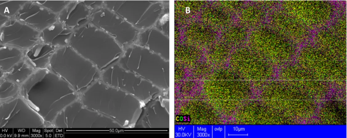
Fig. 1. Scanning electron micrograph of silica-cellulose template
A
B
Fig. 2. Scanning electron micrograph of silica skeleton at magnification of (A) 2000x and (B) 3000x.
Fig. 3. SEM-EDX micrograph of silica-cellulose template.
A A
25
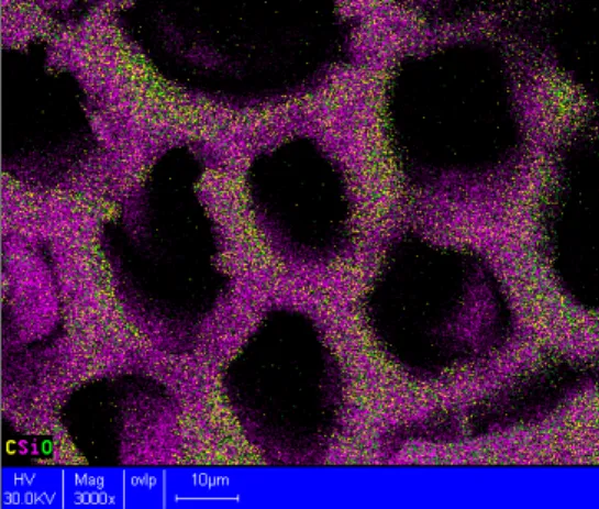
Epoxy composites containing a silica frame, which mimic the cellular structure of wood were prepared through impregnation of silica skeleton with an epoxy resin. The fragile frame was strengthened by the epoxy resin which filled the empty lumens (Fig. 4). The impregnation with epoxy resin slightly distorted the otherwise perfect cellular structure of silica skeleton. The silica frame in the epoxy–silica composite can be seen clearly using SEM- EDX, as shown in Fig. 5.
A B
Fig. 4. Scanning electron micrograph of epoxy-silica composite and its C-O-Si-Kα X-ray map at 3000x.
A B
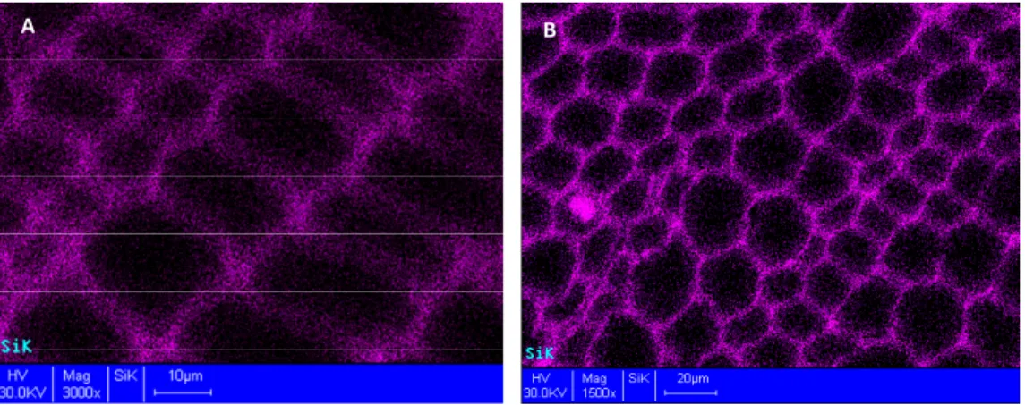
Fig. 5. SEM-EDX images of Si-Kα X-ray map at magnification of (A) 3000x and (B) 1500x.
4. Conclusion
A high quality of cellular microstructure replication of wood was achieved either with retention of the cellulose fibre skeleton or with a completely synthetic silica replica.
Infiltration with epoxy resin and subsequent curing formed composite retaining the cellular structure of wood. Minimal distortion of the original wood cells occurred in the epoxy composite derived from the replicas. The techniques described demonstrate biomimetic preparations of semi-synthetic and synthetic composites based on wood that retain the morphology of the wood.
Acknowledgments
The authors would like to acknowledge the facilities, the scientific and technical assistance of the Australian Microscopy and Microanalysis Research Facility at the RMIT Microscopy and Microanalysis Facility, RMIT University.
References
[1] Fengel D and Weneger G 1984 Wood (Berlin, New York: Walter de Gruyter).
26 [2] Van Opdenbosch D 2011 J. Mater. Res. 26 1193.
[3] Fan T, Chow S and Zhang D 2009 Prog. Mater. Sc. 54 542.
[4] Daud N, Shanks R A, and Kong I 2012 World J. Eng., 9 385.
[5] Greil P, Lifka T and Kaindl A 1998 J. Eur. Ceram. Soc. 18 1961.
[6] Ota T, Takahashi M, Hibi T, Ozawa M, Suzuki S and Hikichi Y 1995 J. Am. Ceram.
Soc. 78 3409.
[7] Singh M and Salem J A 2002 J. Eur. Ceram. Soc. 22 2709.
[8] Yongsoon S, Jun L, Jeong H C, Zimin N and Exarhos G J 2001 Adv. Mater. 13 728.
[9] Cao J, Rambo C R and Sieber H 2004 J Porous Mater. 2004 11 163.
[10] Cao J, Rusina O and Sieber H 2004 Ceram. Int. 30 1971.
[11] Sun B, Fan T, Zhang D and Okabe T 2005 J. Adv. Mater. 37 76.
[12] Sun B, Fan T, Zhang D and Okabe T 2004 Carbon 42 177.
[13] Drum R W 1968 Science 161 175.
[14] Furuno T and Immura Y 1998 Wood Sc. Tech. 32 161.
[15] Gotze J, Mockel R, Langhof N, hengst M and Klinger M 2008 Ceramics 52 268.
[16] Saka S and Ueno T 1997 Wood Sc. Tech. 31 457.
27
Poly(trimethylene terephthalate) Block Co-polymer with Epoxy Resin:
Preparation, Characterization and Properties
Sarath Chandrana,b, c, S. Thomasa, b, R. A. Shanksc
a School of Chemical Science, Mahatma Gandhi University, Kottayam, Kerala, India 686560.
b Centre for Nanoscience and Nanotechnology, Mahatma Gandhi University, Kottayam, Kerala, India 686560.
c School of Applied Sciences, RMIT University, Melbourne, Australia.
Processing of thermoplastics can be facilitated by plasticizer, though after processing the plasticizer remains to modify the properties of the product.
Investigation of the plasticizing action of diglycidyl ether of bisphenol-A (DGEBA) epoxy resin for poly(trimethylene terephthalate) (PTT) using Fourier transform infrared spectroscopy, Raman spectroscopy and differential scanning calorimetry led to the introduction of a novel block co-polymer (DGEBA-block-PTT-block-DGEBA). The novel block co-polymer, formed by the reaction between the end groups of PTT and the oxirane ring of DGEBA, was dependent on the pH of the medium.
1. Introduction
Poly(trimethylene terephthalate) (PTT), first synthesized and patented in 1941 [1], remained obscure till recent times due to the high cost of production. Recent discovery of bioengineering route to synthesize 1, 3-propanediol [2] [3], has rekindled the scientific interest in this polymer. The unique zig-zag structure of PTT renders it a stretch recovery which is about 2-3 times greater than polyamides and other polyesters [4]. The use of epoxy resin as a modifier for PTT based blends has been tried by different researchers [5], [6] but the mechanism of modification was not addressed in these studies. The main aim here was to investigate how the addition of diglycidyl ether of bisphenol-A (DGEBA) epoxy resin affect the melting properties, glass transition temperature of PTT and the mechanism for plasticizing action of DGEBA which remained unattended is explained here.
2. Experimental 2.1 Materials used
DGEBA epoxy resin (Lapox L-12) with an epoxy equivalent between 5.25-5.40 eq·kg-
1and viscosity between 1.15-1.20 g·cm-3 was procured from Atul Industries, India.
Poly(trimethylene terephthalate) (PTT or SORONA 3G) with a density between 1.3-1.5 g·cm-
3, Mn of 22,500 g·mol-1 and degree of polymerization of 2.5 was kindly supplied by DuPont Industries USA. Details of the materials used are given in Table 1and their chemical structures are given in Figure 1. All \materials were used without further purification.
28 Table 1. Characteristics of PTT, DGEBA and DDS
Poly(trimethylene terephthalate)
Diglycidyl ether of bisphenol-A
Diammino diphenyl sulfone
Mw(a) (g· mol-1) 58,400 - -
Mn(a) (g· mol-1) 22,500 - -
Viscosity(b)
(g·cm-3) - 1.15-1.2 -
Epoxy content(b)
(equ·kg-1) - 5.25- 5.40 -
Tg(c) (°C) 54 -16 -
Tm(d) (°C) 227 - 150
∆Href (e)(J· g-1) 146 - -
Supplier DuPont Industries, USA. Atul Industries, Gujarat, India.
Atul Industries, Gujarat, India.
(a) Molar mass estimated by gel permeation chromatography (Perkin-Elmer). Polystyrenes with low polydispersity were used as standards.
(b) Information provided by the supplier.
(c) Glass transition temperature as determined by DSC.
(d) Apparent melting temperature for the neat polymer during a first heating scan.
(e) The melting enthalpy of PTT crystals [7].
O C
CH3
CH3
O CH2 CH
OH
CH2 O
n
O C
O
C O
O CH2 CH2 CH2
m Diglicidyl ether of bisphenol-A
Poly(trimethylene terephthalate) (n≠ m) Figure 1: Chemical structure of DEGEBA and PTT.
2.2 Blend preparation
PTT with varying amounts of DGEBA (5, 10, 20, 30 %·w/w) were prepared by using a Haake mixer. The blends were heated to 240 °C for 900 s with constant shearing at 80 rpm.
After mixing the blends were removed and used for the study.
3. Equipment
3.1. Differential Scanning Calorimetry
Perkin-Elmer DSC7 (Shelton, CT, US), calibrated for temperature with indium and zinc standards, and for enthalpy with indium, was used for the analysis of the blends under a
29
nitrogen atmosphere. A new sample was used for each DSC experiment. The samples were exposed to different thermal histories:
3. 1. (A) Glass transition temperature determination.
Blends prepared were annealed at Ta =260 °C for 1 min, followed by cooling at a rate of 100 K·min-1 to -50 °C and held for 1 min The samples were then reheated 260 °C at a rate of 10 K·min-1.
3.1. (B) Samples were annealed at Ta= 260 °C for 1 min followed by cooling at a rate of 20 K·min-1 to the Tc of 205 °C and held until crystallization was complete. The half-time of crystallization was determined at Tc = constant. The same procedure was applied for the determination of the melting temperature. After crystallization sample was heated to 260 °C at a rate of 10 K·min-1.
3.2 Infrared Spectroscopy Analysis
Fourier transform infrared (FTIR) spectroscopic studies were performed on neat polymers and the blends using attenuated total reflection (ATR) using Perkin-Elmer Spectrum One Spectrometer (Lanstrisant UK). FTIR spectra were recorded in transmittance mode over the range of 4000- 600 cm-1 by an averaging 16 scans at a resolution of 4 cm-1 in all cases.
3. 3. Raman spectroscopy analysis
Raman spectroscopy analysis was performed on neat PTT and the blends using Perkin-Elmer Raman Station 400F Raman spectrometer.
4. Results and Discussion
Miscibility studies using modulated temperature DSC (MTDSC) shows that as the amount of DGEBA in the blends increases the glass transition temperature (Tg) decreases.
Experimentally observed Tg values were fitted with the Fox equation and it shows that the blend exhibit a negative deviation from a Fox equation fitting. The experimentally observed Tg values and the Fox equation fitting results are shown in Figure 2.
Figure 2: Plot of Tg against DGEBA concentration for PTT-DGEBA blends, (a) represents the experimentally observed values and (b) represents the Fox equation fitting.
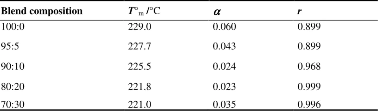
The equilibrium melting temperature (T°m) determined by using Hoffman-Weeks equation shows a regular decrease as the amount of DGEBA in the blends increases indicating that DGEBA can act as a plasticizer. The results of Hoffman-Weeks fitting are tabulated in Table 2.
30
Table 2: T°m and correlation coefficient (r) for Tm versus Tc relationship in the Tc range of 185-205 °C for PTT-DGEBA blends.
Blend composition T°m /°C αααα r
100:0 229.0 0.060 0.899
95:5 227.7 0.043 0.899
90:10 225.5 0.024 0.968
80:20 70:30
221.8 221.0
0.023 0.035
0.999 0.996
The T°m values decreaseed as the amount of DGEBA increased in the blends. Analysis of the epoxy networks using FTIR spectroscopy is widely followed by researchers and the peak at 915 cm-1 is characterized as that of the oxirane ring [8], [9]. In the case of PTT-DGEBA blends it was observed that the peak at 915 cm-1 disappeared completely indicating the possibility of chemical reaction between the hydroxyl and carboxylic acid end groups of PTT and the epoxy group of DGEBA. The experimentally observed FTIR spectrum is shown in Figure 3.
Figure 4: FTIR spectra of the blends, dotted lines represent the areas of interest.
The peak at 1464 cm-1 is assigned to gauche –CH2 group of the crystalline region [10]
indicating that the PTT retains its crystallinity in the blends. This possibility of chemical reaction between the end groups of PTT and DGEBA was further confirmed by Raman spectroscopy. Raman spectroscopy is more sensitive to polarizable bonds and less sensitive to polar bonds [11]. Epoxy ring produces two intense peaks at 846 cm-1(epoxy deformation) and at 1259 cm-1 (in-plane deformation of the epoxy ring) [11]. The peak at 1259 cm-1 corresponds to the breathing mode of benzene rings and so the peak at 846 cm-1 is to be considered as the
31
presence of un-reacted epoxy groups. Raman spectroscopy results show that the peak at 846 cm-1 disappear completely confirming a chemical reaction between the end-groups of DGEBA and PTT.
3000 2500 2000 1500 1000 500
Intensity (a.u)
Raman Shift (cm-1)
50 %· w/w of DGEBA
20 %· w/w of DGEBA
10 %· w/w of DGEBA
1259 847
Figure 5: Raman spectroscopy results for PTT-DGEBA block co-polymers.
This shows that when the amount of DGEBA was between 0-30 %·w/w the pH of the medium induced a chemical reaction between the end groups of PTT and DGEBA. The nucleophiles (hydroxyl and carboxylic acid) at the ends of PTT attack the oxirane ring of DGEBA leading to it ring opening. This reaction leads to the formation of a block co-polymer (DGEBA-block- PTT-block-DGEBA). Further characterization of this novel block co-polymer by NMR spectroscopy was not successful due to practical difficulties.
5. Conclusion
A chemical reaction between the end groups of DGEBA and PTT was followed by using FTIR spectroscopy and Raman spectroscopy. Results showed that a chemical reaction occurred between the terminal hydroxyl and carboxylic acid end group of PTT and the oxirane ring of DGEBA. This chemical reaction was found to be highly sensitive to the amount of DGEBA which in turn can be correlated to the pH of the medium because when the amount of DGEBA was ≥ 40 %·w/w no ring opening reaction was observed. A steady decrease in the Tg as observed in the MTDSC studies shows that the block co-polymer formed follow a negative deviation from the Fox equation fitting. The steady decrease in the Tm° value indicate that DGEBA can act as a plasticizer for PTT. This result has been reported earlier by different researchers. The FTIR and Raman spectroscopy analysis shows that the plasticizing action of DGEBA is due to the formation of a block co-polymer. This novel block co-polymer (DGEBA-block-PTT-block-DGEBA) can find use in a variety of fields.
32 Acknowledgement
The authors thank: (1) Prof. H. W. Kammer and Senior Lecturer Dr. C. H. Chan, Universiti Teknolo