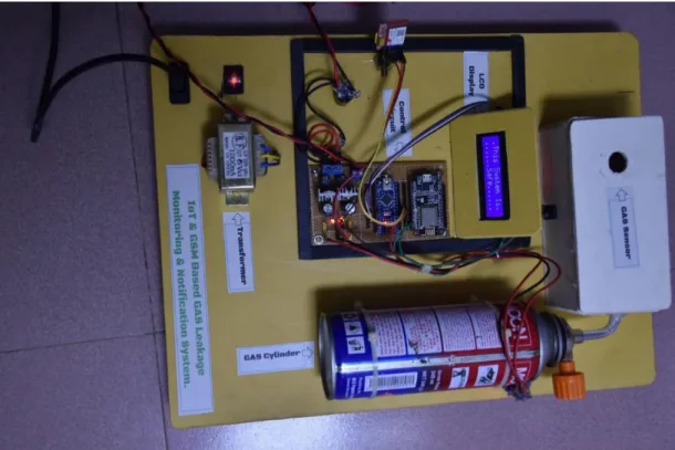
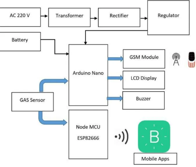
The main objective of the work is the design of the toxic gas detection and signaling system based on microcontroller. Thus this system helps to keep informed about gas leaks by providing the position of the risk of gas leaks through a website. Sensitive to LPG, Propane, Hydrogen The output voltage increases along with the concentration of the measured gases.
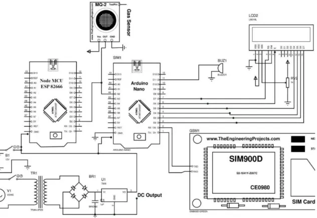
The working principle of the IOT-based gas leakage and monitoring system was demonstrated by the operation of the MCU node attached with the embedded system with the required gas input and output level using gas sensors. Using this system, the choice of using real-time gas leakage monitoring and detection of gas output levels was clearly observed. In particular, a gas sensor was used, which has a high sensitivity for propane (C3H8) and butane and warns of leakage (C4H10 sending). However, the system consists of a gas leak in the event of a fire and sends an SMS to the household.
Another approach uses a smartphone security phone, attached to a gas leak sensor that detects the leak and triggers a warning alarm and sends an SMS to the homeowner and emergency services. Node MCU was launched on October 13, 2014, when Hong published the first nodemecu firmware file to GitHub. Two months later, the project expanded to an open hardware platform when developer Huang R published an ESP8266 gerber board file called devkit v0.9.[12] Later that month, Tuan PM ported the MQTT client library from Contac to the ESP8266[ SoC platform and committed to the Node MCU project, and then the Node MCU was able to support the MQTT IoT protocol by using Lua to access the MQTT broker.
Another major update occurred on January 30, 2015, when Devsaurus ported the u8glib to the Node MCU project, allowing Node MCU to easily drive LCD, Display, OLED, and even VGA displays.
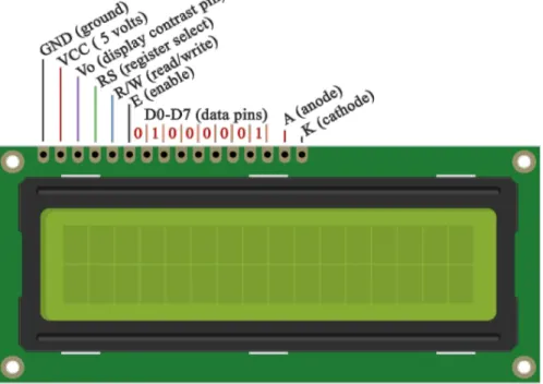
LCD DISPLAY
When Arduino.cc started developing new MCU boards based on non-AVR processors like the ARM/SAM MCU and used in the Arduino Due, they had to modify the Arduino IDE so that it would be relatively easy to change the IDE to support alternative toolchains to allow Arduino C/C++ to be compiled for these new processors. A "core" is the collection of software components required by the Board Manager and the Arduino IDE to compile an Arduino C/C++ source file into the machine language of the target MCU. This has become a leading software development platform for the various ESP8266-based modules and development boards, including Node MCUs.
A command is an instruction given to the LCD to perform a predetermined task such as initializing it, clearing its screen, setting the cursor position, controlling the display, etc.
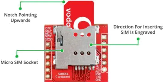
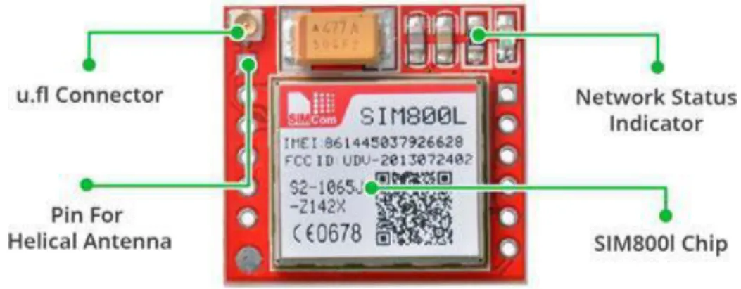
GSM Module
All the necessary data pins of the SIM800L GSM chip are broken out into headers with a pitch of 0.1 inches. The module usually comes with a spiral antenna and can be soldered directly to the NET pin on the PCB. The board also has a U.FL connector provision in case you want to keep the antenna away from the board.
The correct direction for inserting the SIM card is usually engraved on the surface of the SIM socket. An external power source such as Li-Po battery or DC-DC converters rated at 3.7V 2A would work. If you absolutely got the module in a bad space, pull this pin for 100ms to perform a hard reset.
GND is the Ground Pin and should be connected to the GND pin on the Arduino. It is high by default and will flash low for 120ms when a call is received.
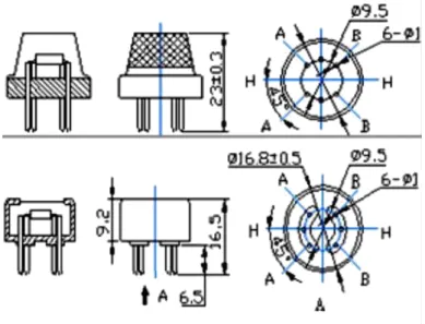
Gas Sensor MQ-2
It is low cost and suitable for various flammable gas detection applications. Widely used in household gas leak alarm, industrial flammable gas alarm and portable gas detector. 3 Digital We can also use this sensor to get digital output from this pin by setting an output threshold value using the potentiometer.
1 H-Pins Of the two H-pins, one pin is connected to the power supply and the other to ground. Can be used to measure or detect LPG, alcohol, propane, hydrogen, CO and even methane.
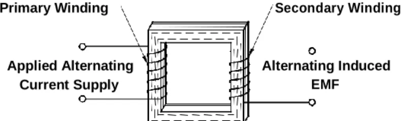
Transformer
The wire used in the two windings, primary and secondary, is coated with an insulating varnish. When a conductor or coil is moved in a stationary magnetic field, it shortens the lines of magnetic flux and an EMF is induced in the conductor or coil. The same principle also applies when a conductor is held stationary and the magnetic flux is made to vary or change.
A magnetic field will build and collapse in the coil, continuously rising and falling in harmony with the applied alternating current, as shown in Figure 3.14. If coil 1 and coil 2 are mounted on an iron core, the magnetic flux will be concentrated around both coils. The input coil of a transformer is powered from the AC supply and is called the primary winding.
It is important to remember that there is no electrical connection between the primary winding and the secondary winding of a transformer. The purpose of the full-wave rectifier (FWR) is to create a rectified AC output from a sinusoidal AC input signal. It does this by using the non-linear conduction properties of diodes to direct the path of the current.
The filtered full wave rectifier is created from the FWR by adding a capacitor across the output. The size of the ripple depends on the size and frequency of the input voltage, the filter capacitance and the load resistance. To describe the voltage ripple source, consider the performance of the filtered full-wave rectifier above.
Let Vi be the full-wave rectified signal input to the filter stage of the rectifier and Vo the output. In the period from T0 to T1, the diode D1 (or D3, depending on the phase of the signal) is forward biased since Vi > VC1 (approaching the forward biased diode as a short circuit). From T1 to T2, the diodes D1 and D2 are reverse biased (open circuit) because Vcap > Vi, and the capacitor discharges through the load R with a time constant of RC seconds.
Capacitor
Capacitance is expressed as the ratio of the electric charge (Q) on each conductor to the potential difference (V). The SI unit of capacitance is the farad (F), which is equal to one coulomb per volt (1 C/V). Typical capacitance values range from about 1 pF (10−12 F) to about 1 mF (10−3 F). The capacity is greater when there is a smaller distance between the conductors and when the conductors have a larger surface area.
In practice, the dielectric between the plates allows a small amount of leakage current and also has an electric field strength limit, known as the breakdown voltage.
Resistor
Theory of operation
Capacitors are widely used in electronic circuits to block direct current while allowing alternating current to pass.
SOFTWARE DESCRIPTION
- Arduino software
- Proteus
- Microcontroller Simulation
- PCB Design
On Rev1 boards: connecting the solder jumper to the back of the board (near the map of Italy) and then resetting 8U2. Arduino Uno is one of the latest smart microcontroller units and has a number of facilities to communicate with a computer, another Arduino or other microcontrollers. An ATmega16U2 on the board channels this serial communication over USB and appears as a virtual communication port to software on the computer.
The Arduino software includes a serial monitor which allows simple textual data to be sent to and from the Arduino board. The RX and TX LEDs on the board will blink when data is being transmitted through the USB-to-serial chip and the USB connection to the computer (but not for serial communication on pins 0 and 1). The Arduino IDE uses the GNU toolchain and AVR Libc to compile programs, and to upload programs it uses avrdude.
Because the Arduino platform uses Atmel microcontrollers, Atmel's development environment, AVR Studio or the newer Atmel Studio, can also be used to develop software for the Arduino. The Proteus Design Suite is a proprietary software tool suite used primarily for electronic design automation. Shape-based automatic routing was added in 2002, and in 2006 there was another major product update with 3D board visualization.
More recently, a dedicated IDE for simulation was added in 2011, and MCAD import/export was included in 2015. High-speed design support was added in 2017. Feature product releases are typically biannual, while maintenance-based service packs are released as needed. The microcontroller simulation in Proteus works by applying either a hex file or a debug file to the microcontroller part of the schematic.
The PCB Layout module is automatically provided with connection information in the form of a netlist from the schematic capture module. The 3D Viewer module allows the developing board to be viewed in 3D along with a semi-transparent height plane representing the board enclosure. The STEP output can then be used to transfer to mechanical CAD software such as Solid works or Autodesk for precise table assembly and positioning.
RESULT AND APPENDIX
Our Result
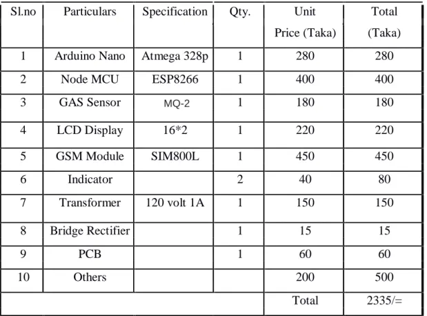
Appendix
CONCLUSION
- Conclusion
- Future Scope
- Advantage
- Application
1] Selvapriya C, Sathya Prabha S, Abdul Rahim M, Aarthi K C, 'LPG Leakage Monitoring and Multilevel Alerting System', International Journal of Engineering Sciences & Research Technology, ISSN November, 2013. 2] AravindaBeliraya, GSM-based Gas Leak Detection System Using Arduino ', International Journal of Engineering Technology Science and Research, ISSN Volume 4, Issue 10, October 2017. 6] T.H.Mujawar, V.D.Bachuwar, M.S.Kasbe, Deshmukh, 'Development of Wireless Sensor Network System for LPG Gas Leak Detection Systems', International Journal of Science .
Ezeofor, „Design and Implementation of SMS Based Industrial/Domestic Gas Leakage Monitoring and Detection Alarm System‟, International Journal of Engineering Trends and Technology (IJETT), ISSN Volume 35, Number 9, May 2016.