LIST OF TABLES
NOMENCLATURE
GREEK SYMBOLS
SUBSCRIPT
INTRODUCTION
Motivation
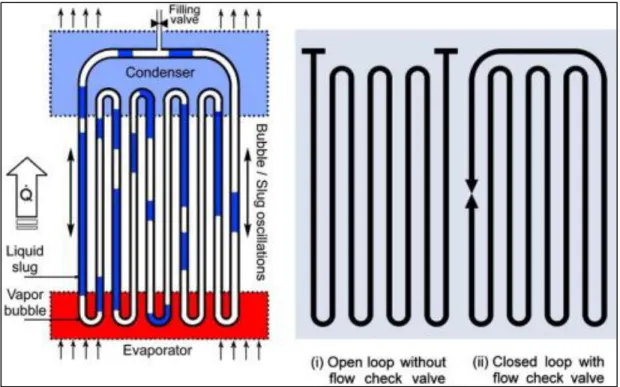
One such device that uses self-generated thermally driven two-phase power oscillations for enhanced passive heat transfer is a pulsating heat pipe (PHP), also known as an oscillating heat pipe (OHP). In line with these developments, the introduction of pulsed heat pipes in the early 1990s as a promising heat transfer technology, especially suitable for thermal management of electronics.
Objectives
The pressure effect of the bubbles created in the system and the effect of flow on thermal variation are considered negligible in our experiment.
LITERATURE REVIEW
Heat Pipe
- History of heat pipe
- Types of heat pipe
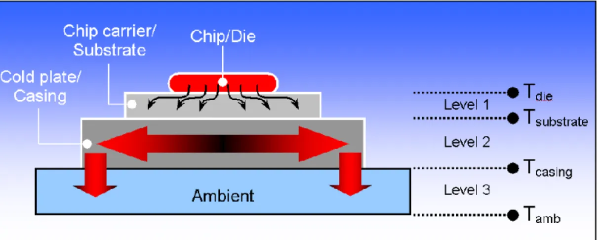
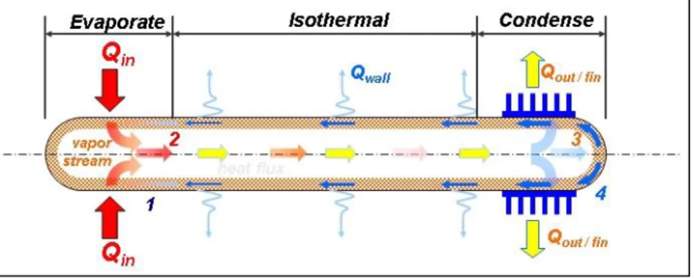
- Key Components of a Heat Pipe
The thermal conductivity of the heat pipe and the phenomenon of phase change are used to dissipate heat to the surroundings. This type of heat pipe uses centrifugal action to return the working fluid to the evaporator.
Close Loop Pulsating Heat Pipe
- Pulsating heat pipe
- Evolutions of PHP
- Parameters affect the performance of CLPHP
- Design/Geometric Parameters: Diameter and material of tube
- Orientation of PHP
- Number of turns
- Design of evaporator and condenser section
- Bend Effect
- Operating Parameters: Filling ratio
- Heat Flux/Temperature
- Dry out condition
- Properties of Working Fluid
The effects of various non-dimensional parameters on the performance of PHP were also investigated. The diameter of the heating pipe plays a decisive role in the selection of the heating pipe because it affects the performance of the PHP.
Limitations of CLPHP
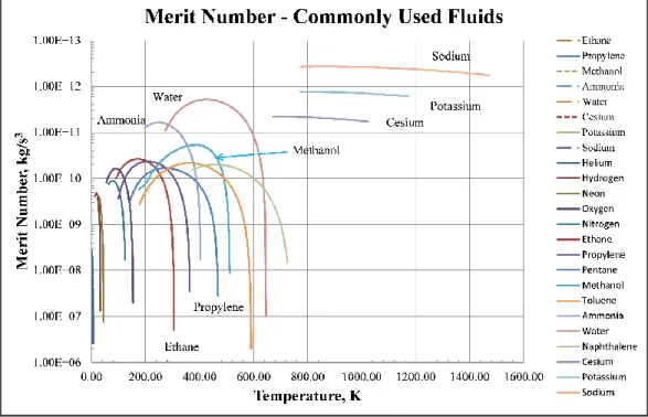
- Merit Number
The number of merits as a function of temperature is shown in Figure 3 for a number of typical heat pipe working fluids. It is very clear from the figure why water is chosen as the working fluid of the heat pipe whenever possible.
Heat Transfer by convection
Experimental setup
- Apparatus
Description of Different types of Apparatus
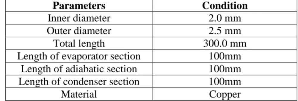
- Pulsating heat pipe
- Working Fluid
- Methanol
- Ethanol
- Distilled Water
- Test Stand
It is the part of the heat pipe where heat is rejected from the working fluid. At room temperature, it is a polar liquid and is used as an antifreeze, solvent, fuel and as a denaturant for ethanol.
Heating apparatus
- Power Supply Unit
- Nichrome Wire
- VARIAC
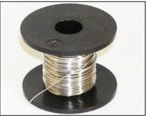
A wooden frame is used as the basic structure on which all other equipment is mounted. The evaporator part is connected with Ni-C thermal wire (Nichrome Wire) which is connected to the variac. Because of Nichrome wire's high internal resistance, it heats up quickly when electricity is applied, and it also cools quickly when it is turned off or removed from a heat source.
We used Nichrome wire in our experiment for heating the test section whose internal resistance was about 18 m. It is connected to the power supply unit to provide variable power (heat input) by varying voltage output.
Insulating Apparatus
- Mica Tape (Electric Insulation)
- Glass Wool (thermal Insulation)
- Foam tape
- Asbestos tape
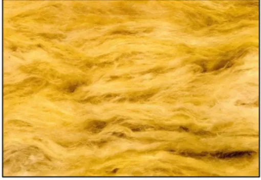
Glass wool is an insulating material made from glass fibers arranged by means of a binder into a texture similar to wool. Glass wool is produced in rolls or in sheets, with different thermal and mechanical properties. The modern method of making glass wool is the invention of Games Slayter, working at the Owens-Illinois Glass Co.
Foam tape also finds use in cabling and wiring systems, where several wraps can provide distance and adhesion between multiple cables. The gray adhesive tape that everyone has come to know and love its name from its very practical function; The adhesive tape was intended to be used for gluing various types of ducts, especially those used for heating.
Cooling Apparatus
- Adapter Circuit
The axial fan in general, whether unidirectional axial fans or others, is the most commonly used version of the cooling fan, as well as the most cost-effective. Sometimes referred to as a "box fan", they move air along a straight axis through the fan. By reducing the fan speed, the noise generated by the axial fan can be reduced.
Due to this low level of audible noise, as well as their economical price range. So to run the fan, an inverter circuit is needed to convert the AC current to DC current.
Measuring Apparatus
- Temperature Sensor (LM35)
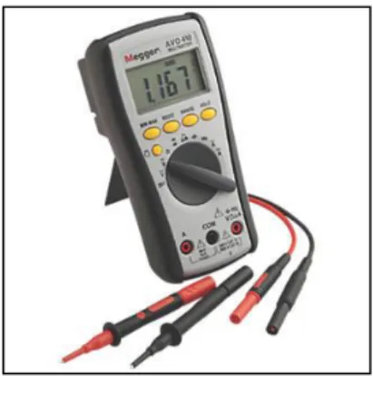
- Multimeter
- Arduino Mega 2560 micro-controller
- Arduino 1.5.2 Compiler
32 on the wall of pulsating heat pipe; 3 for evaporator section, 3 for adiabatic section and the rest 3 for condenser section. The best advantage of using the sensors can be extracted by connecting them to Arduino microprocessor to get accurate data and readings using programming language. The LM35 generates a higher output voltage than thermocouples and may not require the output voltage to be amplified.
From the overall perspective, we thought of lm 35 as it is cheap in price and effective. It has 54 digital input/output pins (of which 15 can be used as PWM outputs), 16 analog inputs, 4 UARTs (hardware serial ports), a 16 MHz crystal oscillator, a USB connection, a power jack, an ICSP header, and a reset button.
Other Equipment
- Glue Gun
- Electric Wire
Mathematical Equations and Calculations
- Calculation of filling Ratio
- Calculation of Heat Input
- Calculation of Thermal Resistance
- Calculation of Heat transfer Co-efficient
Experimental Procedure
First, the heat pipe was filled 28% by working fluid Distilled Water (injection with syringe) and the heat pipes were kept in vertical position. The above three steps were systematically carried out for the working fluid ethanol and methanol respectively.
Precautions
RESULT AND DISCUSSION
Variation of different characteristics of distilled water
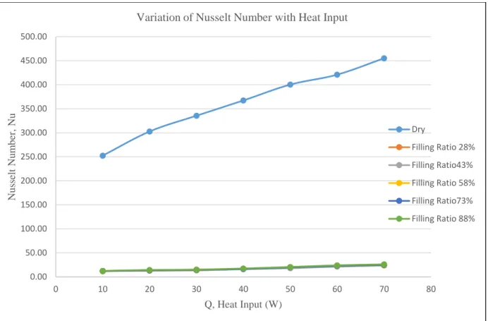
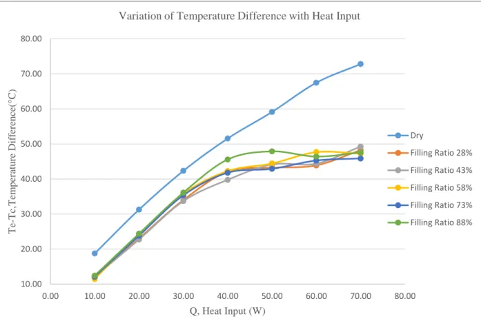
Figure 4.2 shows the effect of different fill ratio on evaporation temperature taking distilled water as working fluid. Here, we can see, there is no noticeable effect of the filling ratio on changing Nu from 28%.
Variation of different characteristics of ethanol
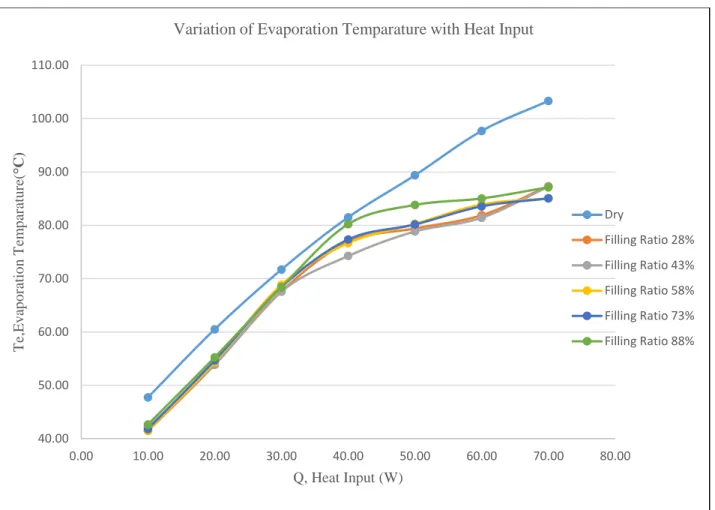
In this figure, the highest evaporation temperature is achieved by the highest fill ratio which is 88%, both at lower and higher heat inputs. In addition, there is very little effect of fill ratio on the evaporation temperature in the case of ethanol. No fill ratio shows a constant rate of increase of condensation temperature with the increase in heat input.
Figure 4.12 shows the effect of filling ratio on the variation of the Nusselt number with the increase in heat input, taking ethanol as the working fluid. With the increase in heat input, the lowest Nu at lower heat input has been observed from 88% fill ratio and the highest has been observed from 58% fill ratio.
Variation of different characteristics of methanol
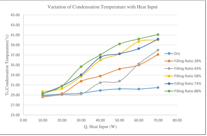
Figure 4.14 shows the effect of filling ratio on the variation of the evaporation temperature with the heat input, taking methanol as the working fluid. Here we can observe that 88% filling ratio achieved the highest evaporation temperature from 10 W to 40 W again from 60 W to 70 W. Figure 4.15 shows the effect of filling ratio on the variation of the condensation temperature with the increase in heat input taking methanol as the working fluid.
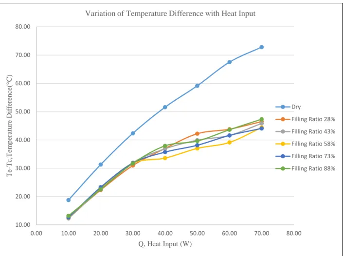
Similar to other working fluids, the ΔT graph showed the small effect fill ratio has on ΔT. It was observed that the heat transfer coefficient for the entire fill ratio increased at a constant rate from 10 W to 30 W.
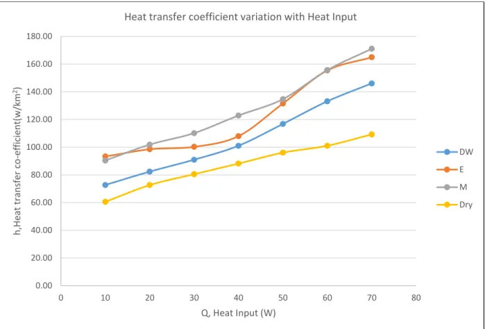
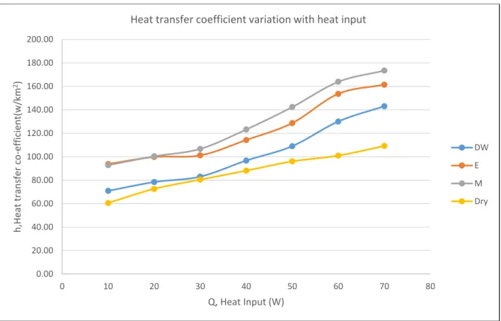
Variation of heat transfer coefficient in different working fluid
Here, the heat transfer coefficient of ethanol was slightly higher than that of methanol at a lower heat input. In this particular chart, at a filling ratio of 58%, the heat transfer coefficient of methanol is higher than that of ethanol and distilled water. It has been seen that the heat transfer coefficient of ethanol increased at a constant rate, but the rate of methanol and distilled water slowed down within 60 W to 70 W.
Figure 4.22 shows the effect of different working fluids on the variation of heat transfer coefficient at the filling ratio of 73%. It was observed that the heat transfer coefficient of ethanol was almost constant from 10 W to 30 W as it behaved at fill ratio of 58% (fig 4.21).
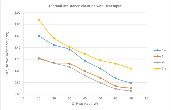
Variation of thermal resistance in different working fluid
Thermal resistance of ethanol and methanol was the same from 10 W to 20 W and then ethanol showed more thermal resistance from 20 W to 70 W. Methanol's thermal resistance was initially more than ethanol but gradually with the increase of heat input it decreased at constant rate. It can be observed that the rate of decrease of thermal resistance of water is more than ethanol and methanol.
The decrease in the thermal resistance of water quickly went from 10 to 20 W, but from 20 to 30 W it slowed down. The thermal resistance of methanol was significantly less than that of ethanol and distilled water from 20 W to 60 W.
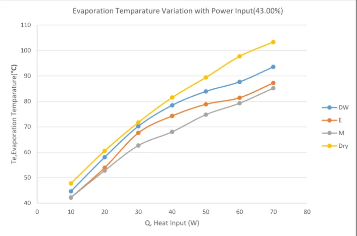
Variation of evaporation temperature in different working fluid
- Variation of condensation temperature in different working fluid
The evaporation temperature of ethanol and distilled water followed the same trend, but the evaporation temperature of ethanol was lower. The water condensation temperature was almost constant from 10 W to 30 W; from 30 W to 40 W it increased rapidly, and then again from 40 to 50 W, at a slower rate. In the case of ethanol, the condensation temperature increased from 10 W to 30 W; then from 30 W to 50 W, it was constant after 50 W increases at a similar rate up to 70 W.
Ethanol, in contrast to lower fill ratios, showed a better steady rise graph of condensing temperature with heat input. Similar to the graph for 73% filling ratio of ethanol, here the ethanol showed the same condensing temperature rise characteristics.
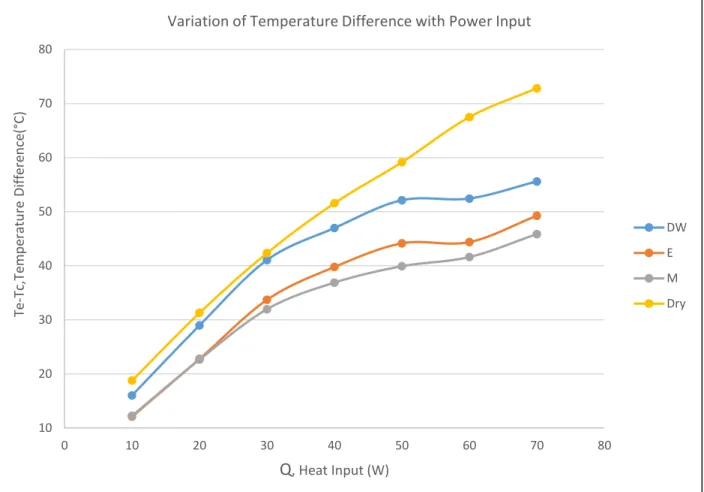
Variation of temperature difference in different working fluid
This figure demonstrates that water and methanol follow the same trend; distilled water is at a higher value. It should also be noted that the rate of increase of ∆T from 10 W to 30 W was higher for all fluids. Figure 4.43 shows the change in temperature difference with heat input for distilled water, ethanol and methanol at 88% fill ratio.
T is found to be almost constant from 40 W to 70 W in the case of distilled water and ethanol.
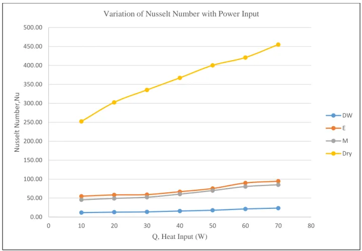
Variation of heat transfer coefficient in different working fluid
With the increase in fill ratio, we can see that the Nu of ethanol drops below ethanol in the heat input range between 30 W and 60 W. The graph follows the same trend as the other fill ratio mentioned in previous figures.
General study
Thermal Resistance Curve Characteristics
In the case of distilled water, according to our experiment, 88% filling ratio gave better result because it showed the lowest thermal resistance. The boiling point and the latent heat of water are greater than ethanol and methanol. Furthermore, the thermal oscillation of water is difficult due to the large surface tension and dynamic viscosity at the initial period.
Therefore, the evaporation section temperature of water PHP is high and the condensation temperature is not significantly higher compared to ethanol and methanol.
Evaporation temperature Curve Characteristics
Condensation temperature Curve Characteristics
Heat transfer coefficient curve characteristics
Nusselt number curve characteristics
Effect of Working Fluid
Applications of Heat pipe
CONCLUSION
- Conclusion
- Recommendations
91 So we can conclude by saying that in our experiment we tried to take comparative data to determine better operating condition so that heat transfer rate can be increased. Different working fluids, binary fluids and nanofluids can be incorporated in this study for more efficient and variable results. Additionally, multiple alloys can be used and Biot number can be taken into account for a more accurate result.
A Computational Fluid Dynamics (CFD) analysis can be performed to investigate the reasons for the difference in thermal resistance and further improvement. Some more parameters like insert/wick structure as parameter, air velocity, heat pipe pulsation orientation, number of loops etc. can be used in further research.
BIBLIOGRAPHY
Holley, B., and Faghri, A., Analysis of pulsating heat pipe with capillary wedge and varying channel diameter, International Journal of Heat and Mass Transfer, vol. Proceedings of the 11th International Heat Pipe Conference, Japan Association for Heat Pipes, Tokyo, Japan, 1999, the identification number for the paper is: pp. S., "Flow Visualization of Oscillating Capillary Tube Heat Pipe," Proceedings of the 11th International Heat Pipe Conference, Japan Association for Heat Pipes, Tokyo, Japan, 1999, pp.
Hosoda, M., Nishio, S. og Shirakashi, R., "Meandering Closed-Loop Heat-Transport Tube (Propagation Phenomena of Vapor Plug)," Proceedings of the 5th ASME/JSME Joint Thermal Engineering Conference, American Society of Mechanical Engineers, New York, 1999 [CD-ROM]. 94 Angles on Operation Limit of Closed-Loop Oscillering Heat-Pipes with Check Valves" American J. B., "Analysis of Liquid-Vapor Pulsating Flow in a U Shaped Miniature Tube," International Journal of Heat and Mass Transfer, Vol. B., Faghri, A., og Zhang, Y., "Thermal Modeling of Un-looped and Looped Pulsating Heat Pipes", Journal of Heat Transfer, bind 123, nr. Zhang, Y., og Faghri, A., "Varmeoverførsel i et pulserende varmerør med åben ende".
Appendix: A