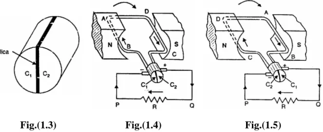
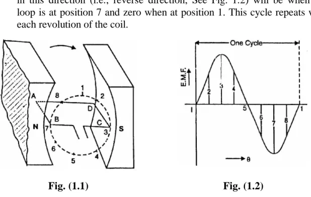
This cycle is repeated with each revolution of the coil. generated in the loop is alternating. The side of the coil 12 at the bottom of the slot is connected to the side of the coil 3 at the top of the second slot.
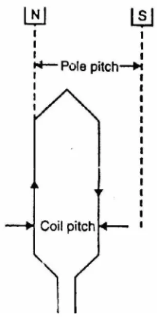
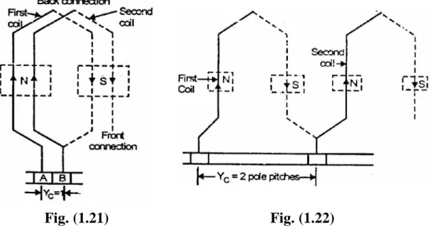
Pole-Pitch
Coil Span or Coil Pitch (Y S )
Full-Pitched Coil
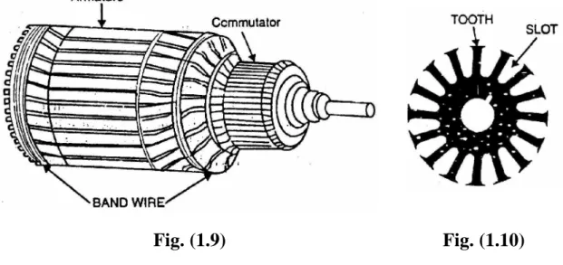
Types of D.C. Armature Windings
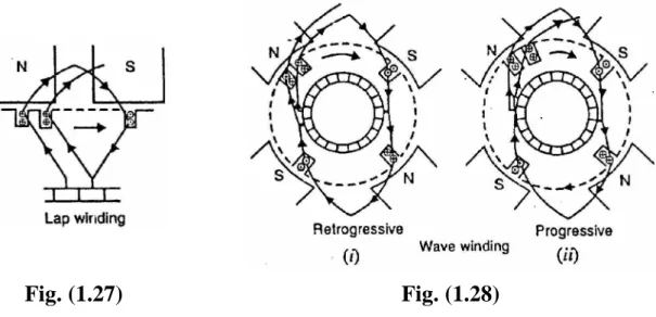
Simplex lap winding
Simplex wave winding
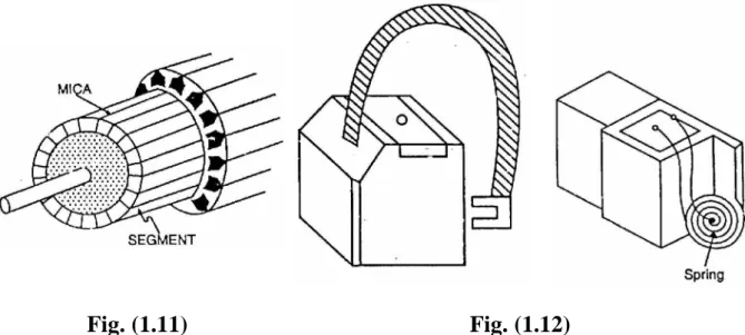
Further Armature Winding Terminology
General Rules For D.C. Armature Windings
The rear pitch (YB) as well as the front pitch (YF) should be almost equal to the pole pitch. The number of commutator segments is equal to the number of slots or coils (or half the number of conductors).
Relations between Pitches for Simplex Lap Winding
This will allow all end connections (back as well as front connection) between a conductor at the top of a slot and one at the bottom of a slot. iii). This is because each coil has two ends and two coil connections are connected at each commutator segment. iv).
Developed diagram
Position and number of brushes
Conclusions
Simplex Wave Winding
If, after passing once around the armature, the coil connects to a segment to the left of the starting point, the coil is retrogressive [See Fig. If it connects to a segment to the right of the starting point, it is progressive [See Fig.
Various pitches
- Design of Simplex Wave Winding
- Dummy Coils
- Applications of Lap and Wave Windings
- Multiplex Windings
- Function of Commutator and Brushes
- Armature Resistance (R a )
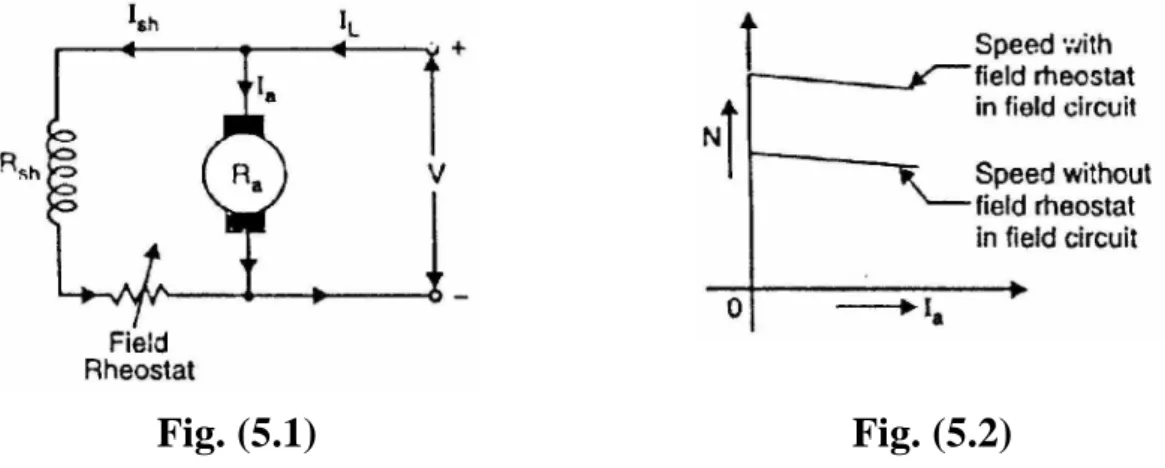
- Types of D.C. Generators
- Separately Excited D.C. Generators
The degree of multiplexing or plexing determines the number of parallel paths in the following way: Note that the number of parallel paths in a multiplexed wave coil depends on the degree of plexing and not on the number of poles.
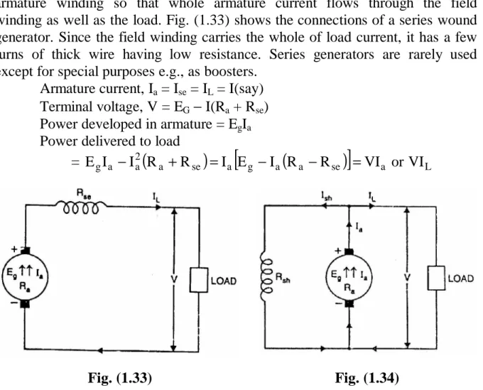
There are three types of self-excited generators depending on the way the field winding is connected to the armature, namely;.
- Brush Contact Drop
- Losses in a D.C. Machine
- Copper losses
- Iron or Core losses
- Mechanical losses
- Constant and Variable Losses
- Power Stages
- Condition for Maximum Efficiency
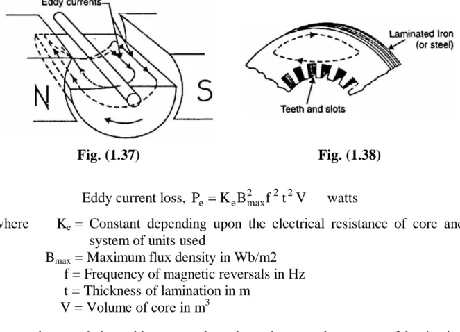
Eddy current loss appears as heat, which raises the temperature of the machine and reduces its efficiency. It should be noted that the eddy current loss depends on the square of the lamination thickness.
Armature Reaction and Commutation
Introduction
- Armature Reaction
- Geometrical and Magnetic Neutral Axes
- Explanation of Armature Reaction
- Demagnetizing and Cross-Magnetizing Conductors
- Calculation of Demagnetizing Ampere-Turns Per Pole (AT d /Pole)
- Cross-Magnetizing Ampere-Turns Per Pole (AT c /Pole)
- Compensating Windings
- AT/Pole for Compensating Winding
- Commutation
For this reason, it is called the cross-magnetization or distortion component of the armature reaction. They are therefore called cross-magnetizing conductors and represent cross-magnetizing ampere-turns of armature reaction.
Ideal commutation
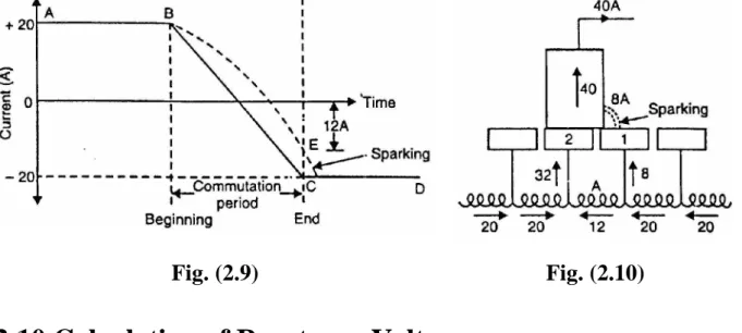
Reversal of current in a coil as the coil passes the brush axis is called commutation. 2.7) (iv) shows the moment when the brush is three-quarters on segment 2 and one-quarter on segment 1. Note that the current in coil A is 10.
Practical difficulties
Calculation of Reactance Voltage
Therefore, the short circuit time (or commutation period Tc) is equal to the time it takes for the commutator to travel a distance equal to the peripheral thickness of the brush minus the thickness of one insulating strip of mica. Suppose Wb = brush width in cm; Wm = mica thickness in cm v = peripheral speed of the commutator in cm/s.
Methods of Improving Commutation
Resistance Commutation
The reverse voltage acts in opposition to the reactance voltage and neutralizes it to some extent. If the reverse voltage is equal to the reactance voltage, the effect of the latter is completely obliterated and we get sparkless commutation.
Other minor advantages of carbon brushes are: i) Carbon lubricates and polishes the commutator. ii). In this method, an arrangement is made to neutralize the reactance voltage by producing a reverse voltage in the coil undergoing commutation.
Interpoles or Compoles
Therefore, the brush shift will depend on the magnitude of the armature current that keeps changing.
Functions of Interpoles
Equalizing Connections
Consequently, the circulating current due to the slight differences in the voltage of the various parallel paths passes through the rectifier rings instead of passing through the brushes. This is due to the fact that conductors in each of the two paths pass successively under all N and S poles (unlike a lap winding where all conductors in any parallel path lie under one pair of poles).
C. Generator Characteristics
- D.C. Generator Characteristics
- Open Circuit Characteristic (O.C.C.)
- Internal or Total characteristic (E/I a )
- External characteristic (V/I L )
- Open Circuit Characteristic of a D.C. Generator
- Characteristics of a Separately Excited D.C
The field current (If) increases from zero in steps and the corresponding value of the generated e.m.f. E0) read on a voltmeter connected via the armature terminals. When plotting the relationship between E0 and If, we get the open circuit characteristic as shown in Figure i. When the field current is zero, some e.m.f.
Generator
Voltage Build-Up in a Self-Excited Generator
Suppose at any instant the field current is i (= OA) and is increasing at the rate di/dt. We come to a very important conclusion that the raised generator voltage is given by the crossing point of O.C.C.
Critical Field Resistance for a Shunt Generator
Critical Resistance for a Series Generator
If the total resistance of the circuit is greater than RC (say OD the line), the generator will fail to generate voltage. represent the total resistance of the field circuit.
Characteristics of Series Generator
- Characteristics of a Shunt Generator
- Critical External Resistance for Shunt Generator
- Critical Speed (N C )
- Conditions for Voltage Build-Up of a Shunt Generator
- Compound Generator Characteristics
There are two critical resistances for a shunt generator namely (i) critical field resistance (ii) critical external resistance. The critical speed of a shunt generator is the minimum speed below which it cannot excite.
External characteristic
Voltage Regulation
The change in generator terminal voltage between full load and no load (at constant speed) is called voltage regulation, usually expressed as a percentage of the full load voltage. If the generator voltage regulation is 10%, it means that the terminal voltage increases by 10% when the load changes from full load to no load.
Parallel Operation of D.C. Generators
Note that the voltage regulation of a generator is determined while the field circuit and speed are held constant.
- Connecting Shunt Generators in Parallel
- Load Sharing
- Compound Generators in Parallel
- C. Motors
- D.C. Motor Principle
- Working of D.C. Motor
- Back or Counter E.M.F
- Significance of Back E.M.F
- Voltage Equation of D.C. Motor
- Power Equation
- Condition For Maximum Power
Therefore the armature current Ia is small and the back e.m.f. is nearly equal to the applied voltage. ii). The motor will stop accelerating when the armature current is just sufficient to produce the reduced torque required by the load.
Limitations
- Types of D.C. Motors
- Armature Torque of D.C. Motor
- Shaft Torque (T sh )
- Brake Horse Power (B.H.P.)
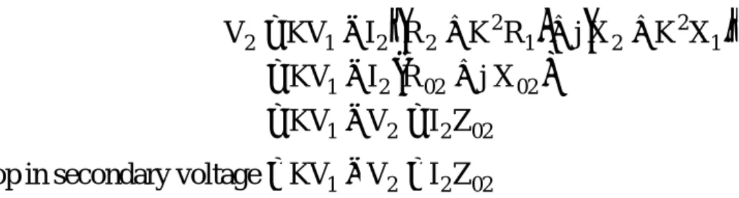
- Speed of a D.C. Motor
- Speed Relations
- Speed Regulation
- Torque and Speed of a D.C. Motor
- Armature Reaction in D.C. Motors
- Commutation in D.C. Motors
- Losses in a D.C. Motor
- Efficiency of a D.C. Motor
- Power Stages
- D.C. Motor Characteristics
So instead of the main flux being distorted in the direction of rotation, as in a generator, it is distorted opposite to the direction of rotation. This is the opposite of the corresponding relationship in a d.c. machine can be used as a motor or generator without changing the commutating pole connections. machine changes from generator to motor, the direction of the armature current reverses.
Both shunt and series types have only one field winding wound on the core of each pole of the motor. The compound type has two separate field windings wound on the core of each pole.
- Characteristics of Shunt Motors
- Characteristics of Series Motors
- Compound Motors
- Characteristics of Cumulative Compound Motors
- Comparison of Three Types of Motors
- Applications of D.C. Motors
- Shunt motors
- Series motors
- Compound motors
- Troubles in D.C. Motors
- Failure to start
- Sparking at brushes
- Vibrations and pounding noises
- Overheating
There is a slight change in the speed of a shunt motor from no to full load. The speed regulation of a cumulative compound motor is therefore weaker than that of a shunt motor.
Speed Control of D.C. Motors
- Speed Control of D.C. Motors
- Speed Control of D.C. Shunt Motors
- Flux control method
- Armature control method
- Voltage control method
- Speed Control of D.C. Series Motors
- Armature-resistance control
- Series-Parallel Control
Only speeds higher than the normal speed can be obtained since the total field path resistance cannot be reduced below Rsh—the shunt field winding resistance. ii). With this method the motor can be driven at any speed up to its maximum speed. a) The speed of the motor can be adjusted through a wide range without resistance losses resulting in high efficiency.
Series-parallel and resistance control
Electric Braking
The motor and its load can be stopped using either (i) mechanical (friction) braking or (ii) electrical braking. In mechanical braking, the engine is stopped due to the friction between the moving parts of the engine and the brake bearing ie.
In electric braking, the kinetic energy of the moving parts (i.e. the motor) is converted into electrical energy, which is dissipated in the resistor as heat or returned to the power source (regenerative braking).
Note that there is some braking torque (TB = k5) even when the motor speed is zero.
- Speed Control of Compound Motors
- Necessity of D.C. Motor Starter
- Types of D.C. Motor Starters
- Three-Point Starter
Consequently, if the motor is directly connected to the mains, the armature will draw a strong current (Ia = V/Ra) due to the small resistance of the armature. Eb increases) and eventually shuts off completely when the engine reaches full RPM.
Operation
One end of the lever is connected through the overload release coil to terminal L. This current will increase the number of ampere turns of the overload coil and pull on armature C, shorting the zero voltage coil.
Drawback
Four-Point Starter
Grading of Starting Resistance—Shunt Motors
A is moved from the OFF position to pin 1, the field and armature circuits are activated and the entire starting resistance is in series with the armature. A is on pin 4 and the entire starting resistance is cut out of the armature circuit. iii).
Starter Step Calculations for D.C. Shunt Motor
As the armature accelerates, the induced emf. back-e.m.k.) increases and the armature current decreases. When the current has dropped to the predetermined value I, the starting arm is moved to tapping point 2. When the starter arm moves to (n + 1) the tap point, all external starting resistance is cut away, leaving only the armature resistance Ra.
Testing of D.C. Machines
Efficiency of a D.C. Machine
We can then use equation (ii) or equation (iii) to determine the efficiency of the machine.
Efficiency By Direct Loading
Swinburne’s Method for Determining Efficiency
When the losses of the machine are known, its efficiency at any desired load can be determined in advance. It should be noted that this method is applicable to those machines where the current is practically constant at all loads, e.g. shunting and assembly machines.
Advantages of Swinburne’s test
Disadvantages of Swinburne's test
Regenerative or Hopkinson’s-Test
Principle
Since the machines can be tested under full load (of course at the cost of power corresponding to the losses in the two machines), the temperatures rise and the commutation qualities of the machines can be observed.
Circuit
Calculations
Since the machines can be tested under full load (of course at the cost of power corresponding to the losses in the two machines), the temperatures rise and the commutation qualities of the machines can be observed. i) Assuming that both machines have the same efficiency η. But if accuracy is required, the efficiency of the two machines should be calculated separately as below. ii) Assuming that iron, friction and wind losses are the same in both machines.
Alternate Connections for Hopkinson’s Test
The main difference is that the shunt field windings are now connected directly across the lines. Iron, friction and windage losses of the two machines are VI1 minus armature Cu losses of the two machines i.e.
Advantages of Hopkinson’s Test
Retardation or Running down Test
The armature's kinetic energy is used to overcome friction, wind and iron loss. ii). Now the armature's kinetic energy is used up only to overcome friction and wind loss.
Theory of retardation test
Moment of Inertia (I) of the Armature
Therefore, we perform another experiment with which either I is calculated or it is eliminated from the above expression.
Electric Loading in Retardation Test
Since the values of I1, t1 and t2 are known, the armature's moment of inertia I can be determined.
Transformer
Transformer
Working
- Theory of an Ideal Transformer
- Voltage Transformation Ratio (K)
- Practical Transformer
- Practical Transformer on No Load
- Ideal Transformer on Load
- Practical Transformer on Load
Consider that an alternating voltage V1 of frequency f is applied to the primary as shown in fig. It can be noted that energy is transported from the primary winding to the secondary winding by mutual flux φ which connects both windings.
We shall consider two cases (i) where such a transformer is assumed to have no winding resistance and leakage flux (ii) when the transformer has winding resistance and leakage flux. ii) Transformer with resistance and leakage reactance.
Impedance Ratio
It is important to remember that: i) When transferring resistance or reactance from primary to secondary, multiply it by K2.
Shifting Impedances in A Transformer
Importance of Shifting Impedances
When the impedance Z2 in secondary is transferred to primary, it becomes Z2/K2 as shown in fig. Voltage V1 in the primary, however, when transferred to the secondary becomes K V1 as shown in fig.
Exact Equivalent Circuit of a Loaded Transformer
There will be I2 R2 and I2 X2 drops in the secondary winding so that the load voltage V2 will be less than E2. iii) When the transformer is loaded to carry the secondary current I2, the primary current consists of two components: a) The no-load current I0 to supply magnetizing current and the current required to supply the core losses.
Simplified Equivalent Circuit of a Loaded Transformer
Approximate Equivalent Circuit of a Loaded Transformer
The no-load current I0 in a transformer is only 1-3% of the rated primary current and can be neglected without serious error. Note that all circuit elements are shown external so that the transformer is ideal.
7.11, if we refer all the quantities to one side (primary or secondary), the ideal transformer remains omitted and we obtain the equivalent circuit.
- Approximate Voltage Drop in a Transformer
- Voltage Regulation
- Transformer Tests
- Open-Circuit or No-Load Test
- Short-Circuit or Impedance Test
- Advantages of Transformer Tests
- Separation of Components of Core Losses
- Why Transformer Rating in kVA?
- Sumpner or Back-to-Back Test
This test is performed to determine R01 (or R02), X01 (or X02) and full load copper losses of the transformer. Therefore, reading of wattmeter W2 will be equal to the full load copper losses of the two transformers.
Advantages
Losses in a Transformer
Core or Iron losses (P i )
Copper losses
- Efficiency of a Transformer
- Efficiency from Transformer Tests
- Condition for Maximum Efficiency
- Output kVA Corresponding to Maximum Efficiency
- All-Day (or Energy) Efficiency
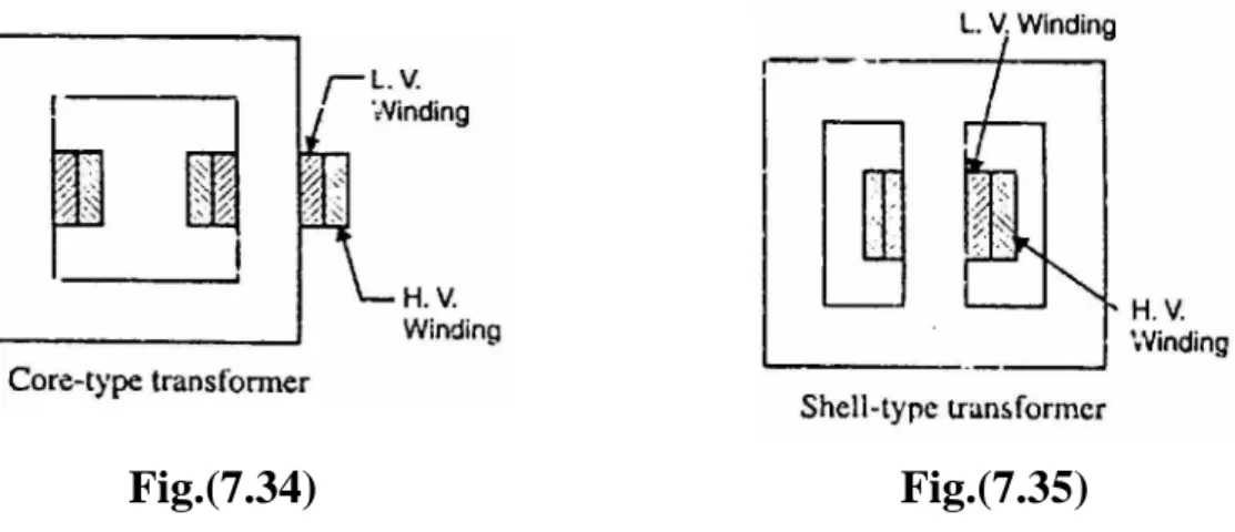
- Construction of a Transformer
- Types of Transformers
- Cooling of Transformers
- Autotransformer
- Theory of Autotransformer
The choice of type (either core or shell) will not greatly affect the efficiency of the transformer. The relative direction of the current through the common portion of the winding depends on the connections of the autotransformer.
Output
Saving of Copper in Autotransformer
The length of copper required in a winding is proportional to the number of turns and the cross-sectional area of the winding wire is proportional to the current rating. Therefore, the volume and hence the weight of copper required in a winding is proportional to the current turns x, i.e.
Advantages and Disadvantages of autotransformers
Therefore, the closer the K value of the autotransformer is to 1, the greater the Cu savings.
Disadvantages
Applications of Autotransformers
Conversion of Two-Winding Transformer Into Autotransformer
Parallel Operation of Single-Phase Transformers
Conditions for satisfactory parallel operation
Single-Phase Equal Voltage Ratio Transformers in Parallel
Secondary e.m.s. of both transformers are the same (ie EA = EB = E) because they have the same turns ratio and the primaries are connected to the same power supply. It is clear that the transformers will share the common load in the same way as two parallel impedances.
Single- Phase Unequal Voltage Ratio Transformers in Parallel
Three-Phase Transformer
Three-Phase Transformer Connections
In the Y-Y connection shown in Fig. or 1/3) of the line voltage is affected in any winding but whole line. Operated in this manner, the bank still delivers three-phase currents and voltages in their correct phase relationships, but the capacity of the bank is reduced to 57.7% of what it was with all three transformers in service.
Three-Phase Transformation with Two Single-Phase Transformers
Power circuits supplied from a Y-Y bank often create serious disturbances in communication circuits in their immediate vicinity. An advantage of this connection is that if one transformer is damaged or taken out of service, the remaining two can be operated in what is known as the open-delta or V-V connection.
Open-Delta or V-V Connection
Theory
- Power Factor of Transformers in V-V Circuit
- Applications of Open Delta or V-V Connection
- Scott Connection or T-T Connection
- Applications of Transformers
Therefore, the power handling capacity of the V-V circuit (without overheating the transformers) is 57.7% of the capacity of the entire ∆-∆ circuit of the same transformers. One end of this primary is connected to the center tap C, and the other end to the terminal R of the three-phase power supply.
This means that the copper losses at full load must be equal to the core losses. That is why they are designed for maximum efficiency between 1/2 and 3/4 of the full load.
Three Phase Induction Motors
- Three-Phase Induction Motor
- Construction
- Stator
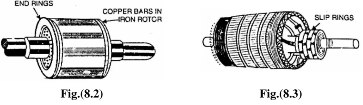
- Rotor
- Rotating Magnetic Field Due to 3-Phase Currents
The magnitude of the resulting flux is constant and is equal to 1.5 φm, as proven under:. The phase sum of − φy and φz is the resulting flux φr [see figure ii). At moment 2 the current is maximum (negative) in φy phase Y and maximum 0.5 (positive) in phases X and Y.
Speed of rotating magnetic field
Direction of rotating magnetic field
- Alternate Mathematical Analysis for Rotating Magnetic Field
- Principle of Operation
- Slip
- Rotor Current Frequency
- Effect of Slip on The Rotor Circuit
- Rotor Current
- Rotor Torque
- Starting Torque (T s )
Due to the relative speed between the rotating flux and the stationary rotor, electromagnetic fields are induced in the rotor conductors. The cause that causes the rotor currents is the relative speed between the rotating field and the stationary rotor conductors.