D
DIU
(IO This proj Degree of B
Dep
DA
SMAR
OT Based ect is subm BSc in EE
artment
AFFODIL
RT CA
d Smart C mitted for f
E (Bachelo T
Su
Zahid ID:
Md. Mos ID:
Su
Dr. M.
Profes Depa
of Electr Faculty
L INTER
FEBR
AR PAR
Car Parki fulfillment or of Scien Technology
ubmitted b
d Hasan H 172-33-4
&
stafizur R 172-33-4
upervised
Shamsu ssor and artment o
rical & Ele y of Engin
RNATIO
RUARY 2
RKING
ing Syste the require nce in Elec y)
by
Himel 4039
Rahman 4064
by
ul Alam Dean of EEE
ectronics neering
NAL UN
2021
G SYST
m Projec ement the ctrical and E
s Enginee
NIVERSI
TEM
ct)
Award of Electronic
ering
ITY
s
© T pr su E in B Si
Z ID
M ID
Si
D Pr D
Si
A L D
©Daffodil Inte This is certif repared by upervision a Electrical an
nternational Bachelor of sc
ignature of Ca
Zahid Hasan H D: 172-33-40
Md. Mostafizu D: 172-33-40
ignature of Su
Dr. M. Shamsu roffesor and D Department of
ignature of th
Arnob Ghosh Lecturer Department of
ernational Un fy that this P
Zahid Has and this proj nd Electronic university cience in Ele andidates
Himel 39
ur Rahman 64
upervisor
ul Alam Dean f EEE (DIU)
he Co-Supervi
f EEE (DIU)
iversity
Lette
Project repo san Himel oject is carri cs Engineer for partial ectrical and E
isor
er of Appr
rt “DIU SM
& Md. Mo ied out by t ring under fulfillment Electronics E
ii
roval
MART CAR ostafizur Ra them in labo Faculty of
of requirem Engineering.
PARKING ahman unde oratory if D Engineering ment for th
SYSTEM”
er my dire Department o
g at Daffod he Degree o
is ct of dil of
©Daffodil International University
Acknowledgement
At first we want to thank ALLAH for giving us the ability to complete our project.
We want to express our deepest gratitude &
appreciation to our supervisor Dr. M. Shamsul Alam & Co- supervisor Mahzuba Islam for their continuous effort to guide us through our project.
We want to thank Daffodil International University &
Department of EEE for giving us the right environment to complete our study.
Special thanks to our families, our friends and our teachers for their unconditional love and support for us.
iii
©Daffodil International University
DEDICATION
Dedicated To
Our Respectable Parents
iv
©Daffodil International University
Abstract
In this time most of the smart city gained so many popularity. It is thankful to the evolution of Internet of things the idea of smart city now seems to be achievable. Smart cities are faces so many problems like that populated, traffic congestion, limited car parking facilities and road safety. We present an IOT based cloud integrated SMART CAR PARKING SYSTEM. The proposed smart parking system consist of an on site deployment of an IOT module that is used to monitor and signalize the state of availability of each single parking space. We can control it by our android operated mobile phone also. From home we can see the parking slot available or engage. Not only this but also we can monitor the each car in time,out time and parking time by sms in our phone. We implement this project by using arduino, 2G GSM module and Wi-Fi module And this is very cheap system.
v
©Daffodil International University
TABLE OF CONTENT
Abstract ii
Acknowledgement iii
Disclaimer and Contribution iv
Table of contents vi
List of Figures ix
CHAPTER 1 : Introduction 1-4
1.Introduction 01
1.1 Objective of the study 02
1.2 Working Procedure 03
1.3 Application 04
CHAPTER 2 : Hardware Description 5-20
2.1 Arduino Nano 05
2.1(a) Power 06
2.1(b) Arduino Nano in/out pin detail 06
2.1(c) Technical Specifications of arduino nano 07
2.1(d) Block diagram of arduino nano 08
2.1(e)Communication 09
2.1(f) Programming 09
2.2 Servo Motor (SG-90) 10
2.2(a) Servo Motor 10
2.2(b) Application 10
2.2(c) Servo motor (SG-90) dimension 11
2.2(d) Wire connection 11
2.2(e) Feature of SG-90 11
2.3 RFID Module (RC522) 12
2.3(a) RFID Reader/Writer module (RC522) 13
vi
©Daffodil International University
2.3 (b) RFID Module pinout 14
2.3(c) Application of FRID 15
2.3(d) RFID pin details 15
2.3(e) RFID Feature 15
2.4 AC/DC Adapter 16
2.4(a) Specification 16
2.5 Wi-Fi Module (ESP 8266) 17
2.5(a) Specification of ESP 8266 17
2.5(b) Application of ESP 8266 18
2.5(c) Power supply for ESP 826 18
2.5 (d) ESP8266 Pinout 18
2.6 GSM Module (SIM800L) 19
2.6 (a) Specification 19
2.6 (b) Application 19
2.6(c) Power supply 20
CHAPTER 3 : SOFTWARE DESCRIPTION 21-22
3.1 Blink 21
3.2 Running Arduino nano 21
3.3 Circuit Daigram 22
CHAPTER 4 : APPARATUS DESCRIPTION 23-28
4.1 20x4 LCD Display 23
4.2 Node MCU V2 25
4.2 (a) Feature 25
4.2 (b) Specification 26
4.3 Voltage regulation (IC 7805) 26
4.3 (a) Application area of IC7805 27
4.4 IR Sensor TCRT5000 28
vii
©Daffodil International University
4.5 20 x 4 LCD display Module 28
4.5 (a) Specification 29
CHAPTER 5 : CONCLUSIONS AND FUTURE 30-31
5.1 Advantage of smart car parking 30
5.2 Disadvantage of smart car parking 30
5.3 Conclusion 31
REFERENCES 32
viii
©Daffodil International University
LIST OF FIGURE
Figure 1.1 :DIU Smart Car Parking 01
Figure 1.2 : Visual Representation of smart car parking 02 Figure 1.3 Measuring displacement of sensor 03
Figure 2.1 : Arduino Nano 05
Figure 2.2 : Block diagram of arduino nano 08
Figure 2.3 : Servo motor SG-90 10
Figure 2.4 : SG-90 Dimension 11
Figure 2.5 : RFID Reader (Sender and Receiver) 12
Figure 2.6 : RFID Reader and Writer 13
Figure 2.7 :RFID Module pinout 14
Figure 2.8 : AC/DC adapter block diagram 16
Figure 2.9 : Wi-Fi Module ESP8266 17
Figure 2.11 : GSM Module SIM800L 19
Figure 3.1 : Blink 21
Figure 3.2 : Circuit Diagram of smart car parking 22
Figure 4.1 : 20x4 LCD Display 23
Figure 4.2 : Generate custom characters 24
Figure 4.3 : Node MCU V2 25
Figure 4.4 : IC 7805 26
Figure 4.5 : Schematic of 7805 IC 27
Figure 4.6 IR Sensor 28
Figure 4.7 20 x 4 LCD Display module pins 29
ix
© Daffodil International University 1
CHAPTER-1
1. Introduction :
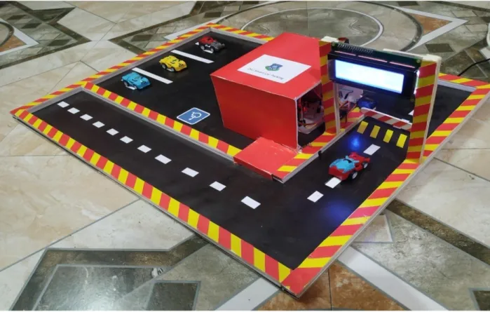
Smart car parking system development by IOT based system. It can send parking data about free and engage places via web or mobile phone application. In this IOT device it is including Microcontroller, GSM module, WiFi module and Sensors are can located each parking place. Admin / user can get the live information data update of the availability of total parking slot and can choose the best parking slot that user want. By investigate technologies of this smart car parking system we innovate an internal research project. Basically the main idea creation of this smart car parking system by using IOT (Internet of Things) and Ultrasonic sensor, where available car parking slot can be displayed in a internet web application.
Fig : 1.1 DIU Smart car parking system
© Daffodil International University 2 1.1 Objective of the Study
1. To Develop an AI (Artificial Intelligent) user friendly smart car parking system that can decrease manual man power and easy traffic control
2. To make a safe and secured car parking slot in special or limited location.
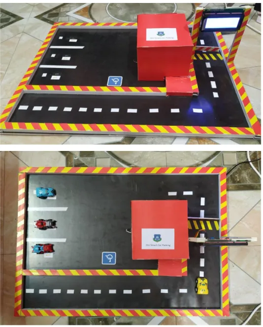
Figure : 1.2 Visual representation of smart parking system
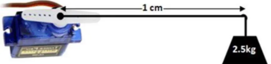
© Daffodil International University 3 1.2 Working Procedure:
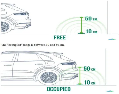
This IOT device made by an ESP8266 microcontroller and a distance measurement sensor which is HC-SR04. The measuring sensor measure the distance and send this data to microcontroller. That is connected with A W S IOT system by the M Q T T protocol. This Electronics device send the measured value data to IOT as a sensor command. These sensor can detect car that is parked in those parking slot by measuring distance by infrared sensor. In our implemented system sensor state will occupied if the distance between range of 100 millimeter or 10 centimeter to 500 millimeter or 50 centimeter and the slot will free if that distance is more than 500 millimeter. By this configured value it represent the status of parking slot that is occupied or free. If the slot is free then user can see “Free” to the display on the other hand if not free then the user can see “Occupied” to the display.
Fig : 1.3 Measuring displacement of sensor.
© Daffodil International University 4 1.3 Application
We can apply this smart car parking system to a small parking and a multi storage parking garage both of them easily.
This is not so coasty and expensive and its system is fully automatic so we need not and manpower to control it. So we can install it every small or large parking garage area.
Free standing garage above ground, under buildings above grade or under builging below grade we can imply it every where.
© Daffodil International University 5
CHAPTER-2
Description of hardware
These hardware components are required for micro controller
1) Arduino nano 2) Servo motor SG 90 3) RC 522 FRID module 4) AC and DC adopter 5) WiFi module ESP 8266 6) GSM module SIM800L
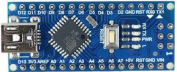
2.1 Arduino nano:
This is small size complete device and it is also breadboard friendly board based device. Though it is a small device but it has more or equal function that arduino duemilanove in a suitable and different circuit. This device has a lack and that is it has dc power jack and it works by using a micro USB cable.
Figure 2.1 : Arduino nano
© Daffodil International University 6 Specification:
❖ MICROCONTROLLER ATMEGA 328
❖ Operating voltage 5 volts
❖ Recommended input voltage 7-12 volts
❖ Limits of input voltage 6-20 volts
❖ 14 In/Out digital pins
❖ 8 analog input pins
❖ 32 Kb of Flash memory
❖ 2Kb of SRAM
❖ 40 mA DC current per input and output
❖ 16 MHz clock speed 2.1 (a) Power:
This Arduino nano takes power by a Micro USB cable and takes 6-20 volts. It can select automatically power source range of highest voltage. There is a FT232 RL chip on this arduino nano and it will be powered if the device is connected with source. If it runs with external power of 3.3 volts then RX and TX LED will flick as digital pins is 0 or 1.
2.1 (b) Arduino nano In/Out pin details :
© Daffodil International University 7 2.1 (c) Technical specification of Arduino nano :
© Daffodil International University 8 2.1 (d) Block diagram of Arduino Nano
Figure 2.2 : Block diagram of Arduino nano
Input and output:
14 digital each pins can be use in Arduino nano as input and output. It is using for three different function and those are
❖ Pin mode
❖ Digital write
❖ Digital read
These each pins operate by using 40mA and 5 volts and it has also an internal pull up resistor of the range of 20-50 kilo Ohm. There are some special functionalized pin for RX , TX and TTL data serial.
Memory:
ATMEGA 328 has 32Kb of memory as flash memory for storing code. Here its boot loader needs 2Kb. This ATMEGA 328 has 2Kb of SRAM and 1Kb of EEPROM.
© Daffodil International University 9 LED indicator:
In this arduino there is a built in LED indicator light. That is connected with those digital pins. In operation time if the pin is high then it will turn on and if the pin is low then it will turn off.
2.1 (e) Communication:
In this Arduino nano here is some wonderful facilities for communicating with other Arduino nano, with a computer or with other microcontroller. ATMEGA 328 can provide TTL series communication that is can do by RX and TX pins. It can also communicate by USB cable and FTDI drivers by some computer software. By these software Arduino nano can sent data by Arduino board. When it transmits data the RX and TX LED indicator will blink. This Arduino also supports TWI and SPI communication.
2.1 (f) Programming :
Arduino nano can be programmed with some arduino software by computer according what we want to do by the arduino nano device. We can also bypass it by ICSP program. This is designed to perform any microcontroller operation by arranging a program and there is a very good side that we can also modify those program. So programming is very important for arduino nano board.
© Daffodil International University 10 2.2 Servo Motor (SG-90)
2.2 (a) Servo motor
There is so many types of servo motors available in buying place but in our project we need a specific servo motor in our work. We know that maximum servo motor is rater DC 5 V to 6.5 V and these motor is for operation of an angle from 0 to 180 degree by there gear arrangement settings and the second factor is the torque. Is this case we choice SG-90 servo motor for our operation.
Figure 2.3: Servo motor SG-90
2.2 (b) Application:
❖ Used in robots for accurate position control
❖ Used for robot movement actuators
❖ For RC car steering
❖ Used in DOF robot
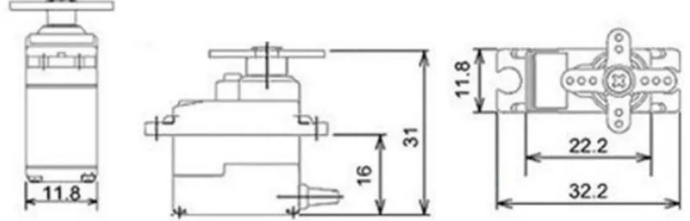
© Daffodil International University 11 2.2 (c) Servo motor (SG-90) dimension
Figure 2.4 : SG-90 dimension
2.2 (d) Wire connection:
Wire
Number Wire Colour Description
1 Red For powering the servo motor
2 Brown Grounding wire for servo motor
3 Orange For PWM signal to drive
2.2 (e) Feature of SG-90
❖ 5 Volts is operating voltage
❖ Very light weight of 9 grams
❖ Plastic gear type
❖ 0 to 180 degree of rotation
❖ 2.5KG/Cm of torque
© Daffodil International University 12 2.3 RFID Module (RC522)
RFID means Radio Frequency Identification. RFID technology basically used for automatic checkout solution. It can identify different kinds of tags. Those tags are attached with some items and this RFID can recognize those tags separately. In our project we use some different tags in some different vehicle as the RFID can recognize those then it will send signal to arduino nano to perform its actions.
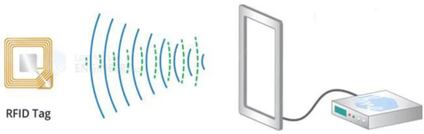
For this project this module is very good choice for considering cost because this module and tags are very cheap and low power needed. RFID mainly consist of two things. That is transponder and receiver. Here Transponder known as tag and receiver known as reader. It use high frequency electromagnetic field and the tags are usually a passive device and it needs no power. Transponder through a radio signal to the tags and then that signal return by those tags electromagnetic reflection. An antenna receive that signal.
Figure 2.5 RFID Reader (Sender and Receiver)
© Daffodil International University 13 After receiving that signal the reader generates an electromagnetic frequency to encode that signal of tags. Then encoder send the data to the microcontroller to perform the operation.
2.3 (a) RFID Reader/Writer module (RC522)
Figure: 2.6 :RFID reader and writer
Here is the reader and writer module. Basically the key ring likes object is the tag and the most important thing is it has 1Kb memory so that we can store some important short data to it and only the reader can do read it when it needs.
This module is designed to produce an electromagnetic field of 13.56 MHz for using the communication with RFID tags. Reader can communicate by controller by SPI system with the maximum data rate of 10Mbps. UARTS protocol communication is also supports by this. This module has an operating voltage of 2.5 – 3.5 volts but its logic pins can tolerate up to 5 volts. For this benefit we can connect this module with controller and with the arduino at same board and this is very important matter because we should not need of any logic level converter.
Specification:
❖ Has SPI and UART host interface
❖ Operating voltage is 2.5 – 3.5 volts
❖ 13.56 MHz ISM band frequency range
❖ Operating current is 13 -26 mA
© Daffodil International University 14
❖ Logic input is 5 volts tolerable
❖ Standard reading range of 5 cm
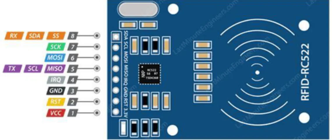
2.3 (b) RFID Module pinout:
This RFID module is designed with 8 pins to perform its action
Figure 2.7: RFID module pinout
❖ VCC needs supply for it self. This module can operate from 2.5 V to 3.5 V.
❖ RST is used for reset input and power down. By put it down it enable power down of internal current.
❖ GND is grounding pin and it needs to connect with arduino.
❖ IRQ is used as an interrupt pin for microcontroller.
❖ MISO SCL and TX is use as master and slave condition applier when we use SPI system.
❖ MOSI is used as master out slave in condition applier.
❖ SCK is use to put serial clock signal pulse to SPI system.
❖ SS SDA and RX is used as signal input for SPI system.
© Daffodil International University 15 2.3 (c) Application of RFID:
❖ Automatic access control system
❖ Automatic costing system
❖ Automatic screening attendance
❖ Automatic Identification system
2.3 (d) RFID pin details
❖ VCC for power input to module
❖ Ground is for grounding the connection
❖ RST is for reset system
❖ SCK is for serial clock pin
❖ IRQ is for Interrupt pin
❖ SS is for serial input
2.3 (e) RFID Features
❖ Operating voltage is from 2.5 to 3.5
❖ 13.56 MHz Module
❖ 10 Mbps data rate
❖ SPI & UART communication support
❖ 5cm range of reading
© Daffodil International University 16 2.4 AC/DC adapter
This is a adapter that have the character of 12 volts and 2 A. It is specially manufactured for electronics devices. This adapter is very popular for circuits.
2.4 (a) Specification:
❖ Input voltage is 100 to 230 V
❖ Output voltage is 12 V
❖ Output current is 2A
❖ 50 Hz of frequency
❖ Output power is 24W
Figure 2.8: AC/DC adapter block diagram
© Daffodil International University 17 2.5 Wi-Fi Module (ESP 8266)
ESP 8266 is useful and cheap wifi module for controlling devices by internet. It works with a microcontroller as like Arduino nano. It also can be programmed to work on its owns.
ESP 8266 was launched in 2014 after that it become very popular. Though it has only one processor but it found on many different breakout boards. These breakout boards have rapidly evoloped over one year.
2.5 (a) Specification of ESP 8266:
❖ Analog to digital conversion
❖ General purpose 16 in/out
❖ Pulse width modulation
❖ 2.4 GHz Wi-Fi supports
❖ Direct memory access
Figure 2.9 : Wi-Fi module ESP8266
© Daffodil International University 18 2.5 (b) Application of ESP8266
This module is self contained SOC with integrated IP. It comes pre programmed with an AT command set firmware. This module is very cheap and effective for growing community.
2.5 (c) Power supply for ESP 8266
This ESP 8266 is not capable for 3-5 volts. It requires an external logic level converter LLC. So it should not be powered directly from board.
2.5 (d) ESP 8266 Pin out
© Daffodil International University 19 Figure 2.10: ESP8266 module pinout
2.6 GSM Module (SIM800L)
SIM800L is very cheap and small GSM breakout board with all advantages of SIM900L.
In this arduino SIM800L sending and receiving text arduino have never been easier.
2.6 (a) Specification:
❖ Chip is SIM800L
❖ Operating voltage is 3.7 to 4.2 volts
❖ Global quad band networks supports
❖ TTL series port
❖ Power module automatically boot
Figure 2.11: GSM Module SIM800L
2.6 (b) Application:
SIM800L from SimCom and arduino UNO are highly recommended due to there popularity and supports from the hobbyist and developer community. SIM800L is a cellular communication module that can make calls, sends email and
© Daffodil International University 20 massage and even connect to the internet. This module is intended like a mobile phone but need external peripheral to function properly.
2.6 (c) Power supply for SIM800L
This module need to be powered by 3.7 volts which is common most standard among cellular modules. One might thing of using the arduino 5v and 3.5v for the module but it is not advisable.
© Daffodil International University 21
CHAPTER 3
SOFTWARE DESCRIPTION
3.1 Blink
Blink make turn an LED for one second and after that it make turn the LED for one second. Most the arduino have this LED.
Figure 3.1 BLINK
3.2 Running Arduino Nano
1. Make run the Arduino
2. Open LED Blink sketch by order 3. Chooses tools
4. Select the serial device
© Daffodil International University 22 3.3 Circuit Diagram
Figure 3.2 Circuit diagram of smart car parking
© Daffodil International University 23
CHAPTER 4
APPARATUS DESCRIPTION
4.1 20 X 4 LCD Display
LDC means liquid crystal display. In our project we use a 20 x 4 LCD display. 20 x 4 LCD display is very common and basic module for any beginner projects. This 20 x 4 translates on a display is 20 characters per line and has 4 lines. In this display is has 5 x 7 matrix.
Figure 4.1 : 20 x 4 LCD Display
Register select
20 x 4 display has types of register, namely, command and data. Here is 0 is for command register and 1 is for data register.
Command regisrer:
Command registers store command in display that command is given instruction to show in display.
Data register:
The data register stores the data to the display and show it on display.
© Daffodil International University 24 Some important command for LCD
01 Clear display screen 02 Return home
04 Decrement cursor 06 Increment cursor 05 Shift display right 07 Shift display left 08 Display off 0C Display on
38 4 lines and 5x7 matrix
Generating custom characters
In LCD display every character is in 5x7 matrix. Here 5 is the column number and 7 is rows number.
Figure 4.2 : Generate custom character
© Daffodil International University 25 4.2 Node MCU versions 2
Node MCU is an source of IOT platform including firmware. It is based on an ESP-12 module. It has some features like 4MB of flash memory, 50Kb of ram, 80 Mhz of system clock and a wifi receiver chip. Its operating voltage is DC 6 to 20 volts and recommended voltage is 7 to 12 volts.
Figure 4.3 : NODE MCU V2
4.2 (a) Features :
❖ Source is open
❖ It is programmable
❖ Cost is very low
❖ Wi-Fi in enabled
❖ Have interactive mode
❖ Small and compact in size
© Daffodil International University 26 4.2 (b) Specification:
❖ Including USB and TTL
❖ Have 10GPIO
❖ Have PCB antenna
❖ Exclude battery
❖ Weight is 10 grams
4.3 Voltage regulator (IC 7805)
We used a voltage regulator for controlling the dc voltage as needed to the module for using a safe voltage source. We use IC 7805. This IC provides +5 volts regulated from power supply and have a heat sink.
Figure 4.4 : IC 7805
This IC is not very efficient and have voltage dropout problem. Some energy can waste by its heat so we use an heat sink on it so that we can reserve it.
© Daffodil International University 27 Schematic of IC 7805
Figure 4.5 : IC 7805 Schematic
4.3 (a) Application area of IC 7805:
❖ Output regulator is fixed
❖ Circuit is reverse bias protected
❖ Adjustable DC voltage
❖ Dual supply regulation
❖ Positive regulation
❖ Reversal protected output polarity
© Daffodil International University 28 4.4 IR Sensor TCRT5000
Figure : 4.6 IR Sensor
Specification:
❖ Sensor has transistor output
❖ Operating temp. -25 degree to +85 degree
❖ Analog or digital output
❖ 60mA Forward current
❖ 5volts operating voltage
4.5 20 x 4 LCD display module
This 12c 20 x 4 screen has a 12c communication interface. It can display 20 x 4 character on 4 lines. We can connect the 12 pins to direct to pin socket and no need to soldering on these pins. All this pins are serial bus and it need to powered by 3.3 volts or 5 voltes.
© Daffodil International University 29 Figure 4.7 : 20 x 4 LCD display module pins.
4.5 (a) Specifications:
❖ Useable with various types of Arduino
❖ 12C address having
❖ Adjustable contrast
❖ Blue back ground with white text
❖ 5volts of supply voltage
❖ Have backlit
❖ Size 82mm x 35mm x 18mm
❖ Have interface address
© Daffodil International University 30
CHAPTER 5
CONCLUSIONS AND FUTURE
5.1 Advantage of smart car parking :
❖ Reduce Traffic : traffic flow will get reduce because this parking users can get parking slot automatically.
❖ Optimized parking : User can find best parking slot by IOT system.
❖ Reduce pollution : By optimized parking system vehicle will burn less fuel.
❖ Enhanced user experience : This smart car parking system will integrate entire system and give a better experience.
❖ Increase safety : User will get a safety can parking because only registered user will have the gate pass and entering access.
❖ Reducing time : it will take less than manual parking garage because here is every thing is automatic.
❖ Storing data : User and parking owner can store and see all data of parking every vehicle as par real time.
❖ Increase service : user will get a better service from this parking slot.
5.2 Disadvantage of Smart car parking:
❖ Maintenance: In a multi storage parking there are so many vehicle and people comes every day and the parking capacity is so large. That’s why it needs to maintenance routinely.
❖ Parking skills: In this parking driver need to have a good parking skills.
© Daffodil International University 31 5.3 Conclusion
This system can save time and traffic and avoiding time wasting. Developed cities can have a great efficiency and security. Smart parking system also can solve population problem and vandalism. Fuel saving also possible by smart car parking system.
© Daffodil International University 32
REFERENCE
1. http:// compoments101.com/microcontroller/arduino-nano 2. http:// mobidiv.biz/blog/iot based smart parking system 3. http:// www.plasmacon.com/ benefits of smart parking 4. http:// www.arduino.ee/en/guide
5. http:// computerhope.com/a/acadapter 6. http://circiutdigest.com/servo motor 7. http:// instructable.com/LCD 12C