Evaluated a model of off-grid electrification with solar energy home system an assessment of the quality of components. 4] Evaluated a model of rural energy access through solar home systems usage patterns and opportunities for improvement.
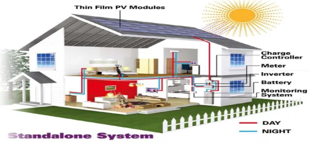
Layout of Modern Home System
DESCRIPTION
DEFINITION OF THE SUN
4.2 : THE STRUCTURE OF THE SUN CONTAINS THE FOLLOWING LAYERS
THE LAYERS OF THE SUN THICK-
SOME FACTS ABOUT THE SUN-
DIFINITION OF ENERGY
Energy
RENEWABLE ENERGY
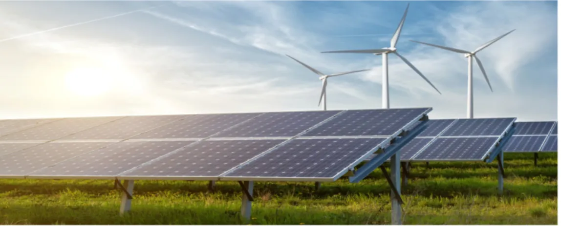
- Main forms/sources of renewable Energy-
- TYPES OF RENEWABLE ENERGY
Several countries and at least two countries, Iceland and Norway, already produce all their electricity using renewable energy, and many other countries have set a target to reach 100% renewable energy in the future.
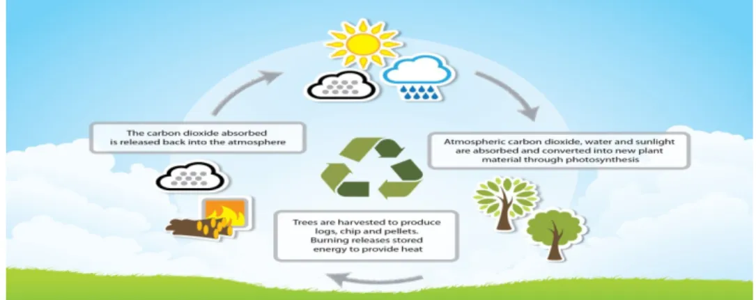
Biomass-
Biomass is organic material derived from plants and animals, and it is a renewable source of energy. Biomass is any organic material—wood, crops, seaweed, animal waste—that can be used as an energy source.
Geothermal Energy-
Many different types of biomass, such as wood chips, corn and some types of waste, are used to produce electricity. Some types of biomass can be converted into liquid fuels called befouled that can power cars, trucks and tractors.
Wind Energy-
The Geysers dry steam reservoir in Northern California is the largest known dry steam field in the world.
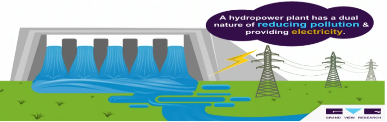
Hydropower-
- Advantages of Renewable Energy
- Renewable energy won’t run out
- Maintenance requirements are lower
- Renewable save money
- Renewable energy has numerous health and environmental benefits
- Renewable lower reliance on foreign energy sources
In most cases, renewable energy technologies require less overall maintenance than generators using traditional fuel sources. In most cases, switching to renewable energy means anywhere from hundreds to thousands of dollars in savings.
SOLAR HOME SYSTEM
- Solar Home System
- Basic Components
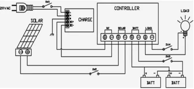
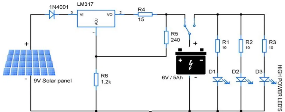
- Circuit Diagram of Solar Home System
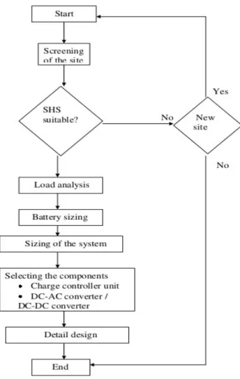
- Site Screening
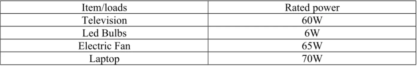
- Load Determination
- Battery Sizing
- Array Sizing
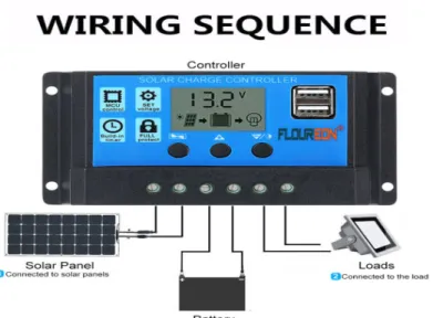
- Selection of Charge Controller
- Selection of Converter
- System Wiring
- Cost of Power from DESCO (3.546 kw-h) (9)
- Comparison Between Solar Home System and Power from DESCO (9)
- Identifying Direct Costs
- Capital costs
- Operating and maintenance Cost
- Advantage of Solar Home System
- Save Money on Electric Bills Immediately
- Protect Yourself Against Rising Energy Costs
- Reduce Your Carbon Footprint
- Conserve Our Natural Resources
- Work Toward Energy Independence
- Increase Your Home Value
- Reduce Utility Bill
- Minimal Environmental Impact
- Limitation of Solar Home System
- SOLA POWER SYSTEM
- Photovoltaic Cell, Module and Array
- ADVANTAGES PHOTOVOLTAIC SYSTEM
- THE WORKING PRINCIPLE OF SOLAR CELL
- CONCENTRATED SOLAR POWER
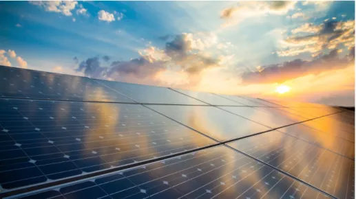
- SOLAR ENERGY
- ADVANTAGES OF SOLAR ENERGY
- Renewable Energy Source
- Reduces Electricity Bills
- Diverse Applications
- Low Maintenance Costs
- Technology Development
Although the production of solar panels requires some inputs of raw materials and energy, the environmental impact of solar energy is minimal. Solar energy is the conversion of energy from sunlight into electricity, either directly using photovoltaics (PV), indirectly using concentrated solar energy, or a combination. Grid-tied systems: These solar energy systems are grid-tied so that the excess power required can be accessed from the grid.
As the name suggests, solar rays in this type of solar power system are concentrated (focused) on a small area by placing mirrors or lenses over a large area. There are different types of technologies that are based on the concentrated solar power to produce electricity. Photovoltaic effect is a method of producing direct current electricity based on the principle of the photoelectric effect.
But for most of the times we need AC power and so solar power system also consists of an inverter. It can be deployed in all areas of the world and is available every day. How much you save on your bill will depend on the size of the solar system and your electricity or heat consumption.
Technology in the solar energy industry is constantly advancing and improvements will intensify in the future. Innovations in quantum physics and nanotechnology could potentially increase the effectiveness of solar panels and double or even triple the electrical input of solar power systems.
Aspects of Solar Energy in Bangladesh
- Crisis of Power in Bangladesh
- Data on power crisis in Bangladesh
- Solar Energy in Bangladesh
- Solar Energy Project
- Development in Solar Energy Program
He points out that the distribution of SHS is highest in Dhaka district, while the use of solar panels is lowest in Sylhet. The main objective of the project is to provide 16,000 SHS in rural areas, which will benefit about 80,000 people. In addition, most power plants are based on gas, which will be phased out in the future.
The right use of renewable energy is the best choice for solving the energy crisis in Bangladesh because it has low costs and fewer risks. Although the country's installed electricity generation capacity has been increased to 12,261 MW, there is scarcity of electricity in the hot summer season, which is a hindrance to both industrial and socio-economic development. The government of Bangladesh has set a plan to generate 3% of the country's total electricity production from renewable sources by 2015 and 10% by 2020.
However, in 2015, the country managed to produce only 3.5% of its total electricity from renewable sources. This article presents a thorough review of the current status and future potential of the renewable energy sector in Bangladesh. This document provides updated information for the entire renewable energy sector in the country [11].
![Table 6.1- Data on power crisis in Bangladesh [6].](https://thumb-ap.123doks.com/thumbv2/filepdfnet/10766792.0/36.892.114.806.148.804/table-6-data-on-power-crisis-in-bangladesh.webp)
IMPROVING THE EFFICIENCY OF SOLAR PHOTOVOLTAIC POWER SYSTEM
- Short circuit current I SC : This is the current that flows through the external circuit
- Open Circuit Voltage (V oc )
- Maximum Power (P MP)
- Improving the Conversion Efficiency of Solar Cell
- Light Energy (Photons) Absorption
- Losses Due to parasitic resistance
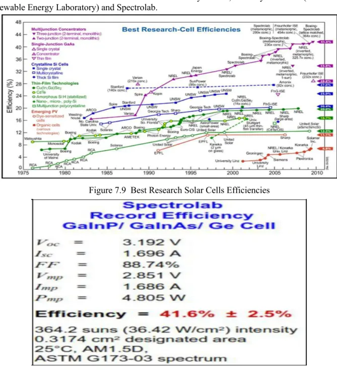
- EVOLUTION OF SOLAR CELLS
The Maximum current and voltage of a typical solar cell is represented at the 4th quadrant of the IV characteristic curve of Figure 1.6, the maximum power is the area of the product of the maximum current Imp and Voltage Vmp as shown in equation 8. The fill factor FF is the ratio of the maximum power (PMP) generated by the solar cell to the product of the open-circuit voltage Voc and the short-circuit current ISC. From the above set of equations, we define the solar cell conversion efficiency η as the ratio of the maximum generated power (PMP=VMP.IMP) to the input or incident.
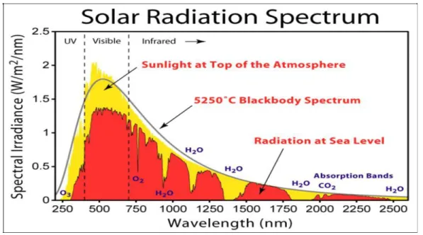
The spectrum of the sun's solar radiation is very similar to that of a black body with a temperature of approximately 5,800 deg K. The path length of the solar radiation through the Earth's atmosphere in units of Air Mass (AM) increases with the angle from the peak. The air mass number is dependent on the Sun's altitude path through the sky and therefore varies with time of day and with the passing seasons of the year, and also with the latitude of the observer.
As the sun's radiation travels through the atmosphere and would encounter various atmospheric diffusion and attenuation, the air mass coefficient of the solar spectrum from the surface of the Earth's atmosphere at typical latitudes is 48.2˚ AM1.5G, the integrated. This differs from the ideal solar cells due to the introduction of series resistance (Rs) which arises from the surface of the cell material to the contacts. The effect of parasitic resistances is that it reduces the area of the maximum power rectangle (VOC.ISC) of the IV characteristic curves and thus.
1st Generation Solar Cells (Crystalline silicon (c-Si) PV technology)
Due to the high cost of manufacturing the first generation solar cells, a second generation solar cell known as thin film technologies was developed. An amorphous material differs from a crystalline material in that there is no long-range order in the structural arrangement of the atoms. Although thin-film PV cells are less prone to breakage and not vulnerable to most of the other manufacturing problems common to crystalline solar cells, their efficiency is significantly lower.
There are also some concerns about the toxic legacy of the materials, both in manufacturing and at the end of life. The amorphous solar cells like the one shown in Figure 1.13 below are very flexible to install as less support is needed when placing panels on roofs and it also has the advantage that panels fit on light materials such as backpacks, textiles etc. The efficiency of thin film technology solar cell is approaching about 20% based on recent research breakthroughs.
- Solar (Photovoltaic) Power System
- Smart Grid Photovoltaic Inverter System (SGPVI)
- Grid-Integrated Photovoltaic Inverter System
- Multi-level Inverter Topology
- Output Voltage and Switching States: The 3- level inverter topology produces three different output voltage levels namely; the DC bus voltage V+, zero voltage and DC bus negative
- The Maximum power point tracking (MPPT): The feature that allows an inverter to remain on the ever-moving maximum power point (MPP) of a PV array is called maximum
- Grid integration and disconnection
- Monitoring and Communications
- IGBT Module
- Power Magnetics
- Transformer
The photovoltaic inverter (PVI) system converts the DC power produced by the PV array into AC power in accordance with the voltage and power quality requirements of the utility grid. Tremendous research is underway to overhaul the grid of the future for smartness and efficiency. Additional advantage of the smart grid is that it must be intelligent to diagnose power outages and detect faults to provide automatic recovery.
One of the critical requirements of these standards is that all grid-connected inverters must disconnect from the grid if the AC voltage or frequency goes above or below the limits prescribed in the standard. Another important function of the software and control part of the system is to control the MPPT functions that vary the DC voltage and. Looking at figure 1.26 above, some of the critical components of inverter systems are: solid state switches ie.
The design choices of these critical components are very important for the efficient operation of a solar energy system.[16] Another very critical part of a grid-tied solar inverter system is the power magnetic components, inductor and transformer. The efficiency of the power magnet (transformer and inductor) is critical to the efficiency of the solar system.
DATA ANALYSIS AND DISCUSSION AND RESULT
Identifying Direct Costs
Capital costs
Operating and maintenance cost
- Solar charge controller sizing
- Solar PV System Sizing
- Size the PV Module
- Inverter sizing
- Battery sizing
- Load Determination
- Performance Comparison of Solar Panel in a day
The maximum wattage (Wp) produced depends on the size of the PV module and the climate of the site location. Calculate the total peak wattage required for the PV modules (for item 1.2) by 3.43 to get the total peak wattage required for the PV panels required to operate the devices. Calculate the number of PV panels for the system. Divide the answer obtained in point 2.1 by the nominal output power in watt-peak of the photovoltaic modules available to you.
Increase each partial part of the result to the next highest full number and that is the number of PV modules required. Installing more PV modules improves system performance and extends battery life. If fewer PV modules are used, the system may not work at all during cloudy periods and battery life will be shortened.
The input power of the inverter must never be lower than the total power of the devices. For standalone systems, the inverter must be large enough to handle the total amount of watts you will be using at one time. For grid-tied or grid-connected systems, the input power of the inverter must be equal to the rated value of the PV array to allow safe and efficient operation.
Voltage Graph
Power Graph
RESULT
CONCLUSION
Solar cells; Operating Principles, Technology and System Applications, Prentice-Hall Inc, 1982 pp xii and pp http://solarsystem.nasa.gov/planets/profile.cfm?Object=Sun&Display=Facts: Date Accessed: 3/11/13. 15] Worden, James and Zuercher, Michael M.; How Inverters Work, Solar Pro, Issue 2.3 April/May 2009 http://solarprofessional.com/articles/productsequipment/inverters/how- inverters-work?v=disable_pagination Date Accessed: 2/2/11. 16] Upadhyaya, Ajay; Yelundur, Vijay; Rohatgi, Ajeet: High Efficiency Monocrystalline Solar Cells With Simple Fabrication Technology: 21st European Photovoltaic Solar Energy Conference and Exhibition, Dresden, Germany; 4-8 September 2006.
18] Worden, James and Zuercher, Michael M.; How Inverters Work, Solar Pro, Edition 2.3. April/May 2009 http://solarprofessional.com/articles/productsequipment/inverters/how- inverters-work?v=disable_pagination Date accessed: 2/2/11.
![FIGURE 4.1 : The Sun with its Layer Structure [3].](https://thumb-ap.123doks.com/thumbv2/filepdfnet/10766792.0/13.892.137.766.259.640/figure-4-1-sun-layer-structure-3.webp)
![Figure 4.2 : Some facts about the Sun [3].](https://thumb-ap.123doks.com/thumbv2/filepdfnet/10766792.0/14.892.171.732.137.391/figure-4-2-facts-sun-3.webp)
![Figure 4.3 : Main forms/sources of renewable Energy [4].](https://thumb-ap.123doks.com/thumbv2/filepdfnet/10766792.0/15.892.217.679.350.708/figure-4-3-main-forms-sources-renewable-energy.webp)