I hereby certify that this project and thesis titled "Global System of Mobile Communications (GSM)-Based Lobster Security System Using PIR (Passive Infrared) Sensors" are being carried out by the following students under my direct supervision and have completed this work in the laboratories of the Department of electrical and electronic engineering of the Technical Faculty of Daffodil International University in partial fulfillment of the requirements for the degree of Bachelor of Electrical and Electronics Engineering. In addition, we would like to thank all our friends for sharing their knowledge; information and help us make this project a success. We would like to express our deepest love and gratitude to our beloved family for being very supportive and also for their non-passive infrared vision and encouragement during our studies at this university.
In this task we have designed a regularly occurring but very fantastic home defense that describes the challenge feature as a function to name the home owner his mobile number. The PASSIVE INFRARED sensor detects change and determines speed by the level of heat emitted by infrared or adjacent objects. This product will detect the hearth within a quick time (maximum 5 seconds) and the records will be sent using SMS to SMS and will be tested using print message and loud sound through LEDs on the most important panel.
The main advantage of choosing this product is the avoidance of all wiring in the main panel and in the slave zones. This cable discount is complemented by the use of the RS-485 network concept, which minimizes the price of 50% of the project costs. Another gain is configuring the gadget settings of the essential panel. The keypad is created via the LCD screen and the area that FIRE detects is displayed on the LCD screen.
INTRODUCTION
- INTRODUCTION TO EMBEDDED SYSTEM
- PROBLEM STATEMENT
- GOALS AND OBJECTIVES
- Methodology
- Project outline
Some of his concrete / his ideas usually start with the introduction of a product (hardware or software), but in the same area and in depth of the current products their deficiency is examined. Moreover, a solution is proposed in a method that is better than that of the previous one to the other. The central node of the wireless sensor community is completely based on the machine GMM module, the statistics collection node, the machine manipulation node and the mobile phone microcontroller.
Wireless sensor network The data collector module integrates the infrared detector, and PASSIVE INFRARED detects the house collects the data in the encrypted alarm board and identifies the size of the wireless network node of the node. Once the central nodes of the wireless sensor network receive an alarm signal, customers are immediately sent to the GOBAL SYSTEM MOBILE COMMUNICATION modules and the GOBAL SYSESTEM MOBILE COMMUNICATION network. The response obtained through the microcontroller depends on it, a name is sent to the SMS or call with the mobile station through a GOBAL SYSTEM MOBILE COMMUNICATION modem, and then the owner of the owner notifies the owner of the house.
When the temperature sensor detects a very high indoor temperature, the sensor at the same time sends the WiFi sensor to the home management center through an encrypted alarm in the network. Once the Wireless Control Center accepts alarm alerts, it immediately sends a short alarm message to users via the GOBAL SYSTEM MOBILE COMMUNICATION module and the GOBAL SYSTEM MOBILE COMMUNICATION network.
LITERATURE REVIEWS
Introduction
Survey
Summary
ANALYSIS OF SYSTEM COMPONENTS
Introduction
Components
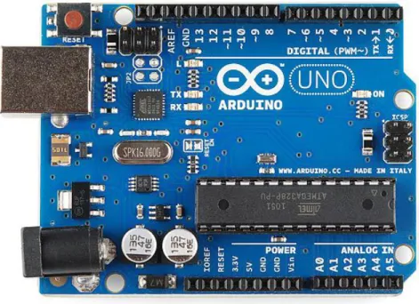
SYSTEM SPECIFICATIONS .1 ARDUINO
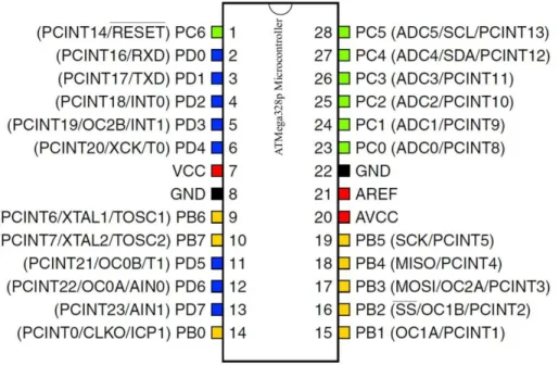
- Microcontroller (ATMega328p)
- a Features ATMega328p
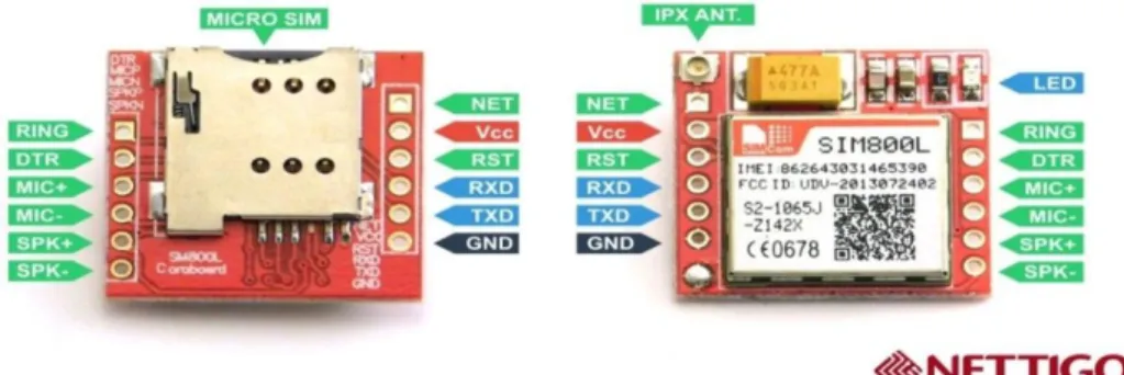
- GOBAL SYESTEM MOBILE COMMUNICATION MODULE
- a Features of SIM800L
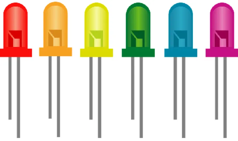
- LIGHT EMITTING DIODE
- PASSIVE INFRARED Sensor with Motion Detection
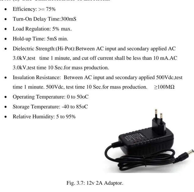
You can power the Arduino via the Uno USB connection or with the help of an external power supply. The adapter can be connected with a 2.1mm center positive plug. If the use is more than 12V, the voltage regulator can hit additional overheating and the boards.
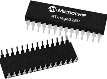
This is the voltage on the Adriano board used by the external power source. We can provide voltage through this pin or if the voltage supply via the power plug can be accessed through this pin. The ATMEGA328P-PU AVR is a Power CMOS 8-bit microcontroller based entirely on the larger RISC architecture.
Effective instructions for single clock cycle, ATmega328P-PU MHz achieves drawings from about 1 MIPS in the vicinity of the system, which is designed to optimize the charge on the machine to optimize a great deal of processing times. AVR Core 32 integrates a wealthy educational kit with common registrars because of the reasons. Designed for the world market, SIM 800 L is a tri-band GOBAL SYSTEM MOBILE COMMUNICATION / GPRS engine operating in frequency EGOBAL SYSTEM MOBILE COMMUNICATION 900 MHz, DCS 1800 MHz and PCS1900 MHz SIM800 GPRS Multi-Slot Type Division 10 (Optional) Functionality and support GPRS coding schemes CS-1, CS-2, CS3 and CS-4 With small configurations of 40mm x 33mm x 2.85mm, SIM 30000 can sound almost all the indispensable area of your utility, such as a smartphone, PDA mobile phone and different cells.
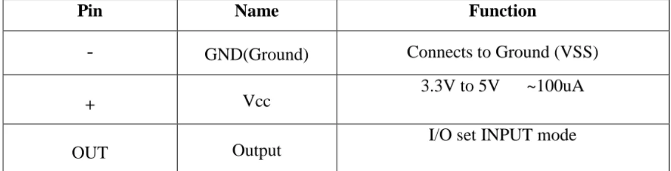
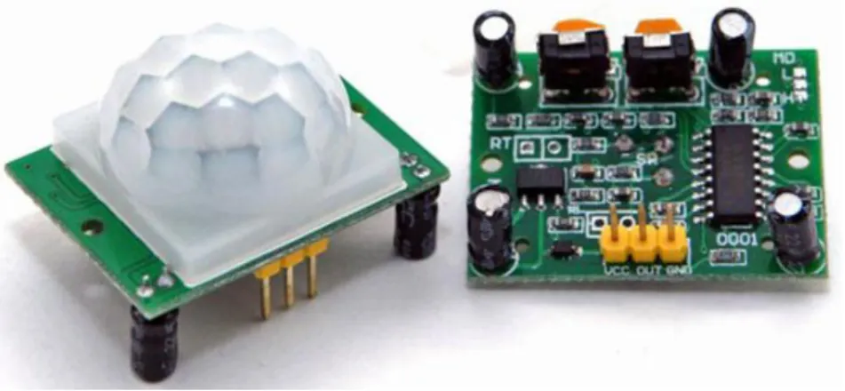
The authentic interface of the cellular software is made by a 60-pin board-to-board connector, which provides all the hardware interfaces between modules and clients. The PASSIVE INFRARED sensor detects the switch of a person in approximately 10 meters from the sensor. PASSIVE INFRARED sensors are amazing, they have flat sketch and minimal effort, have a large variety of lenses and with easy interface.
One pin will be ground, another will be the mark and the final pin will be power. PASSIVE INFRARED serves as a digital output to pay attention to excessive or low flip pens. This help can be detected with a help to get an unmoderated signal into an I/O pin.
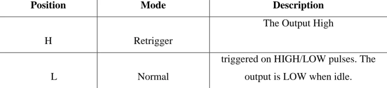
After the sensor is frozen, the output pacing will continue until the output is larger for a few seconds, then it will decrease. If the output continues, the output will be cycled in this way The sensor line however seeing once again PASSIVE INFRARED Sensor accurately wants a warm-up time with a particular truce.
3.3.6 12V 2A ADAPTOR
- Jumper Wire
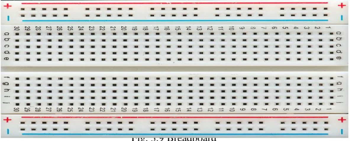
- Breadboard
- A Construction of a Breadboard
- Summary
A jumper wire (also known as jumper wire, or jumper) is an electrical wire, or group of them in a cable, with a connector or pin at each break (or occasionally stopping them - absolutely "canned" ), which is commonly used to connect the components of a breadboard or other prototype or view. When using a breadboard, counties and parties now do not have to promote counties. Fabrics are now no longer offered, you can choose your circuit structure at any time except for any crisis.
It includes a subject blanket of conductive steel clips in white ABS plastic, each clip being heated with different clips. A breadboard is a line of conductive steel strips surrounded by a field made of white ABS plastic. There are a series of holes in the plastic field that are arranged in a male or female fashion.
It consists of two lines, one for the +ve line and the other for the -ve line or ground. All the hardware used in this project is in proper shape and working properly, so GOBAL SYSTEM MOBILE COMMUNICATION must work properly especially on security. In this chapter, we try to talk about the important points about the used hardware description of each character and their work.
DESIGN AND
IMPLIMENTATION
- Introduction
- The Block Diagram
- Circuit Diagram
- Hardware Connection of Description
- Summary
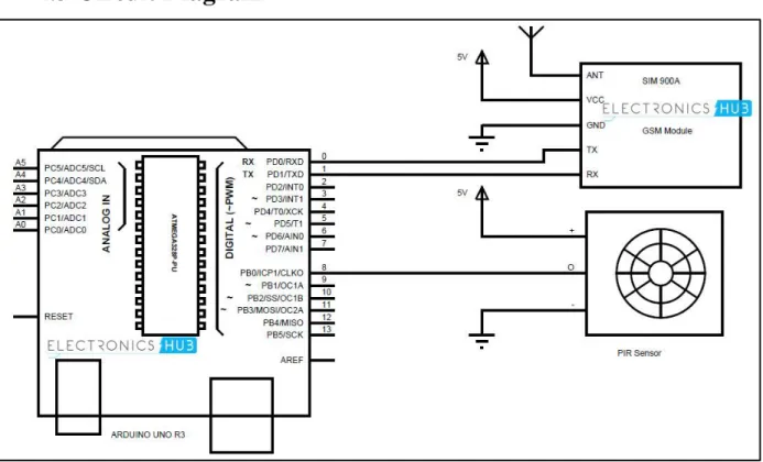
Although it is important to consider when importing program (sketch) into aroodino, the GOBAL SYSTEM MOBILE COMMUNICATION modem will be disconnected due to the fact that it can interfere with the serial communication with Ordino IDE. Rx pin of GOBAL SYSTEM MOBILE COMMUNICATION module is connecting to Tx pin of ARDUINO. The Tx pin of the GOBAL SYSTEM MOBILE COMMUNICATION module is connected to the Rx pin of the ARDUINO.
The output pin of the PASSIVE INFRARED sensor is connected to the ARDUINO pin 5. The Vcc pin of the PASSIVE INFRARED Sensor & GOBAL SYSTEM MOBILE COMMUNICATION Module are both connected to the 5V pin of the ARDUINO. The GND pin of the PASSIVE INFRARED Sensor & GOBAL SYSTEM MOBILE COMMUNICATION Module connects to the GND pin of the ARDUINO.
After all the things are completed in accordance with this chapter, the GOBAL SYSTEM MOBILE COMMUNICATION GSM mainly based home security will be equipped to perform. The main difficult issue about this chapter was once energizing the SIM800L.
RESULT AND DISCUSSION
Introduction
Final Result
Cost Analysis
Summary
CONCLUSION
Conclusion
Limitation of the Work
Future Scope
APPENDIX