We declare that this project work entitled "IoT Based Smart Grid System" is the result of our own work as cited in the references. This is to certify that this project titled "IoT Based Smart Grid System" is being done by the following students under my direct supervision. This project work was carried out by them in the laboratories of the Department of Electrical and Electronic Engineering under the Faculty of Engineering, Sonargaon University (SU) in partial fulfillment of the requirements for the degree of Bachelor of Science in Electrical and Electronic Engineering.
Coordinator, Department of Electrical and Electronics Engineering, SU−Sonargaon University, Dhaka, for his valuable and patient advice, kind help, cooperation, contribution of new idea. The deep theoretical and hardware knowledge and great interest of our supervisor in this field influenced us to realize this project.
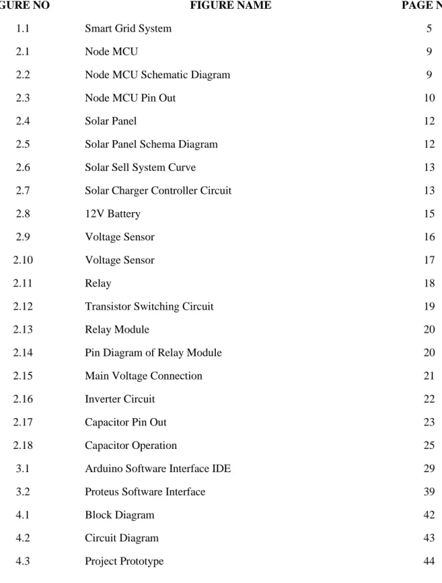
List of Tables
INTRODUCTION
- Background
- Literature Review
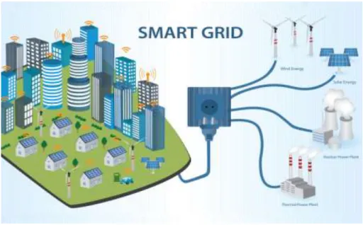
- Smart Grid System
- Application of IoT
- Objective
- Methodology
- Advantages
- Applications
- Limitations
- Future Scope of Work
- Structure of the Project
We proposed an IoT-assisted power monitoring and control system because of the above-mentioned advancements in IoT and its use in power grids. In this way, it is possible to manage the power consumption of the power system, resulting in an overall reduction in power consumption and billing costs. However, the Internet of Things remains mature, especially due to many limitations that limit the full use of the IOT.
The first chapter contains the statement of the introduction, our background study for the project, objectives of the study in the project and the project organization. Chapter four deals with the result and discussion and shows the complete prototype of the project we built.
HARDWARE ANALYSIS
Introduction
Software
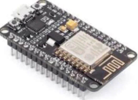
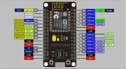
Hardware Description 2.2 Node MCU
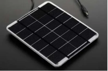
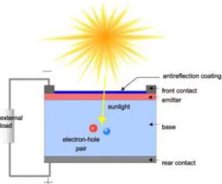
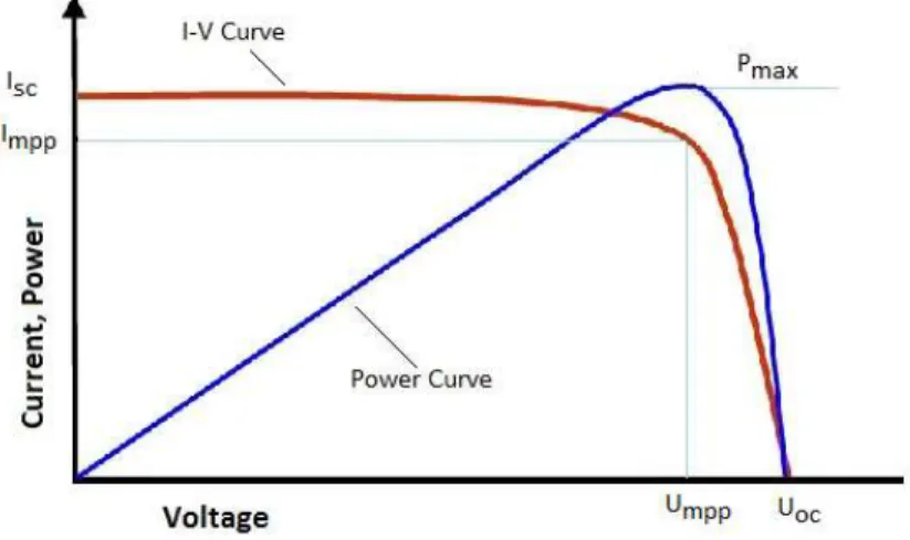
Solar Panel
A solar panel is a set of solar photovoltaic modules that are electrically connected and installed on a supporting structure. A solar panel can be used as an integral part of a larger photovoltaic system to generate and supply electricity in commercial and residential applications. Each module is rated for DC output under Standard Test Conditions (STC) and typically ranges from 100 to 320 watts.
The efficiency of a module determines the area of a module at the same nominal power. An 8% efficient 230 watt module has twice the surface area of a 16% efficient 230 watt module. A photovoltaic system typically includes a panel or array of solar panels, an inverter, and sometimes a battery and/or solar tracker and connecting wiring. They do not store energy. Therefore, to guarantee the flow of electricity when the sun is not shining, it is necessary to store part of the energy produced.
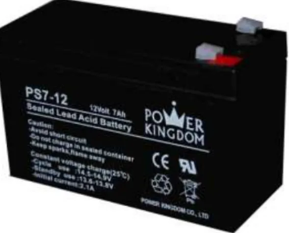
As the battery charges, electrical energy is stored as chemical energy in the cells. When discharging, the stored chemical energy is removed from the battery and converted into electrical energy. In East Africa, the most common type of secondary battery is the lead-acid battery.
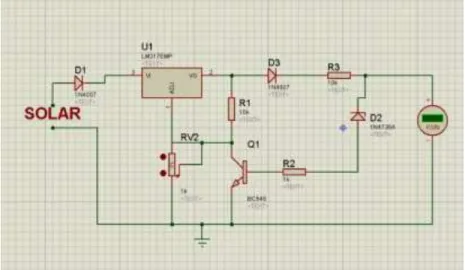
Solar Charger Controller
The current is caused by reversible chemical reactions between the electrodes and the electrolyte in the cell. Here is a solar charger circuit used to charge lead acid or Ni-Cd batteries using the solar energy. When the battery terminal voltage rises above 6.8 volts, the Zener conducts and provides base current to T1.
2.5 12v Battery
Quick Details
AC Current Sensor
The module is equipped with the ZMCT103C series small high-precision current transformers and high-precision op amp circuits for accurate sampling and proper compensation of signals. The required output voltage can be adjusted according to the potentiometer (if the gain ratio is adjusted, the gain range is 0-100 times), but the maximum voltage at the output (OUT) will not exceed 1/2 VCC.
Product Description
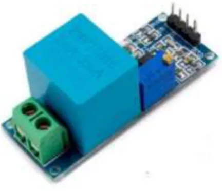
Voltage Sensor
ZMPT101B AC Single-phase voltage sensor module is based on a high precision ZMPT101B voltage transformer. ZMPT101B AC voltage sensor is best for the purpose of the DIY project, where we need to measure the accurate AC voltage with a voltage transformer. It is an ideal choice to measure the AC voltage with Arduino /ESP8266 /Raspberry Pi as an open source platform.
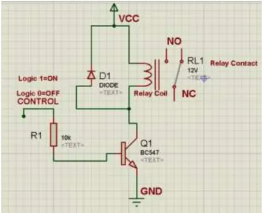
Relay
In a double coil device, when biased voltage is applied to the reset coil, the contacts will pass. AC controlled magnetic latch relays have single coils that use driver diodes to distinguish between run and reset commands. The circuit above is called a low-side switch because the switch—our transistor—is on the low (ground) side of the circuit.
Alternatively, we can use a PNP transistor to create a high-side switch: as with the NPN circuit, the base is our input and the emitter is connected to a constant voltage. Controlling a relay with the Arduino is as easy as controlling an output such as an LED. NO (Normally Open): There is no contact between the common pin and the normally open pin.
So when you activate the relay, it connects to the COM pin and supply is provided to a load. NC (Normally Closed): there is contact between the common pin and the normally closed pin. There is always a connection between the COM and NC pins, even when the relay is off.
When you trip the relay, the circuit opens and there is no supply to a load. If you e.g. want to control a lamp, it is better to use a normally open circuit because we just want to turn on the lamp once in a while. IN2: controls the second relay (it must be connected to an Arduino digital pin if you use this second relay.. otherwise you don't need to connect it).
Capacitor
The capacitor is made of 2 dense conductors (usually plates) separated by a dielectric material. The capacitance is the amount of electric charge stored in the capacitor at a voltage of 1 Volt. Capacitance is measured in units of (F). The capacitor interrupts current in direct current (DC) circuits and short circuits in alternating current (AC) circuits.
The pin that is long is the positive pin and the pin that is short is the negative pin. As shown in the image above, the negative pin is located directly below the negative symbol.
Features
Capacitor parameters selection
Resistor
In electronic circuits, resistors are used to reduce current flow, adjust signal levels, divide voltages, bias active elements, and terminate transmission lines, among other things. High-power resistors that can dissipate many watts of electrical current as heat can be used as part of motor controls, in power distribution systems, or as test loads for generators. Variable resistors can be used to adjust circuit elements (such as a volume control or a lamp dimmer) or as sensing devices for heat, light, humidity, force, or chemical activity.
It avoids the use of a decimal point and replaces the decimal point with a letter loosely related to the SI prefixes corresponding to the resistance of the part. For example, 8K2 as a part designation code in a circuit diagram or bill of materials (BOM) indicates a resistor value of 8.2 kΩ. When the value can be expressed without the need for a prefix (ie a multiplier of 1), "R" is used instead of the decimal point.
SOFTWARE IMPLEMENTATION
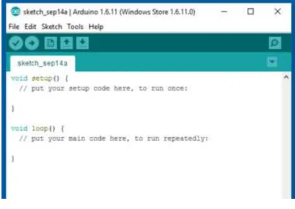
Arduino Software
The lower right corner of the window displays the configured board and serial port. NB: Versions of the Arduino Software (IDE) before 1.0 saved sketches with the extension .pde. Create a new instance of the editor, with the minimum structure of a sketch already in place.
Opens the Preferences window, where some settings of the IDE can be customized, such as the language of the IDE interface. Highlights the next occurrence - if any - of the string specified as the search item in the Find window relative to the cursor position. Highlights the previous occurrence - if any - of the string specified as the search item in the Find window relative to the cursor position.
However, it allows you to use the full capacity of the Flash memory for your sketch. The documents are a local copy of the online ones and may link back to our online website. The Arduino software (IDE) uses the concept of a sketchbook: a default place to store your programs (or sketches).
You can view or change the sketchbook location from the Preferences dialog. This inserts one or more #include statements at the top of the sketch and assembles the library of your sketch. Note that the serial monitor does not handle control characters; if your sketch needs full management of serial communication with control characters, you can use an external terminal program and connect it to the COM port assigned to your Arduino board.
Proteus Software
Adafruit Server
Adafruit IO
Adafruit IO is one such cloud provider that focuses more on cloud IoT deployments.
Objective
Installation
SYSTEM ARCHITECTURE
- Block Diagram
- Circuit Diagram
- Working Principle
- The Project Prototype
- Result
- Cost Analysis
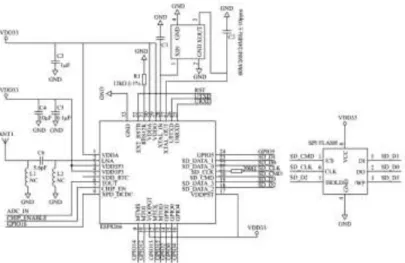
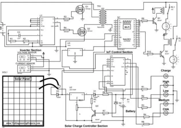
The schematic diagram here represents the electrical circuit and components of the project. The way the whole project works is that we take solar energy storage in a battery. This battery system supplies 12 volts, an inverter converts that DC to AC and supplies 220V AC in this system.
If this system can get more than 30W of power under another load, the whole system will automatically shut down for 5 seconds. If it does not exceed the previous total of watts, the system will shut down again. After the final completion of this project, we ran it and observed the results of this project.
Finally, we have successfully completed our project and check whether our project is executed accurately according to our objective.
DISCUSSION & CONCLUSION
Discussion
Conclusion
A Low SAR Embedded Antenna for Wireless Pacemaker System Monitoring," 4th International Conference on Electrical Information and Communication Technology (EICT) 2019. Parametric design and simulation studies of a compact ultra-wideband antenna for a wireless capsule endoscopy system in an intracorporeal environment," International Journal of Electrical and Electronic Engineering & Telecommunications, 2021. A dry and wet system for waste separation and management,” European Journal of Engineering and Technology Research, vol.
Energy Harvesting Technology from Human Movement”, 2020 Second International Conference on Advanced Information and Communication Technology (ICAICT). Mouchak-An IoT-based smart beekeeping system using MQTT,” 2019 4th International Conference on Robotics and Automation Engineering (ICRAE).
Appendix