NAZMUL HASAN MAJED to the Department of Computer Science and Engineering, Daffodil International University, has been accepted as satisfactory in partial fulfillment of the requirements for the degree of B.Sc. Department of Computer Science and Engineering Faculty of Natural Sciences and Information Technology Påskelilje International University. I hereby declare that this project was carried out by me under the supervision of Dr.
I also declare that neither this project nor any part of this project has been submitted elsewhere for the award of any degree or diploma. Touhid Bhuiyan Professor and Head, Department of CSE, to the other academic members and staff of the CSE Department of Daffodil International University, for their kind help in completing my research. I would like to thank all our coursemates at Daffodil International University who participated in this discussion while completing the coursework.
The roll call method is used by many universities to track attendance, which is a waste of time and energy. Therefore, it is essential to use competent and efficient contemporary systems, as replacing the current attendance system with an RFID system can reduce time and energy waste. The proposed approach suggests that teaching would require a significant amount of teacher time and resources, as the student roll call system is completed using the class list, and it takes time and effort to confirm student attendance.
The primary objective of this project is to design and construct an IoT-based Student Attendance Management System using RFID.
Methodology
Project Outline
Literature Review
Introduction
Literature Review
The GSM network serves as the primary interface between the identification center and the ePassport reader. AES is used to encrypt data for security during transmission over the GSM network, securing server and e-passport reader communications. In [10], an automated presence management system was developed on an electronic and mobile platform using a stationary RFID AR 400 matrix reader with four circularly polarized antennas or a handheld RFID Symbol MC9000-G reader.
VB.net and a database that Ire used in developing this attendance system program (Microsoft Access). To link RFID and the computer system, a serial connection is established between the computer and the RFID reader. When students enter the lecture hall, an RFID reader scans their RFID tags, stores all relevant data (such as access time, name and other details) in a database via a serial connection and keeps the system running.
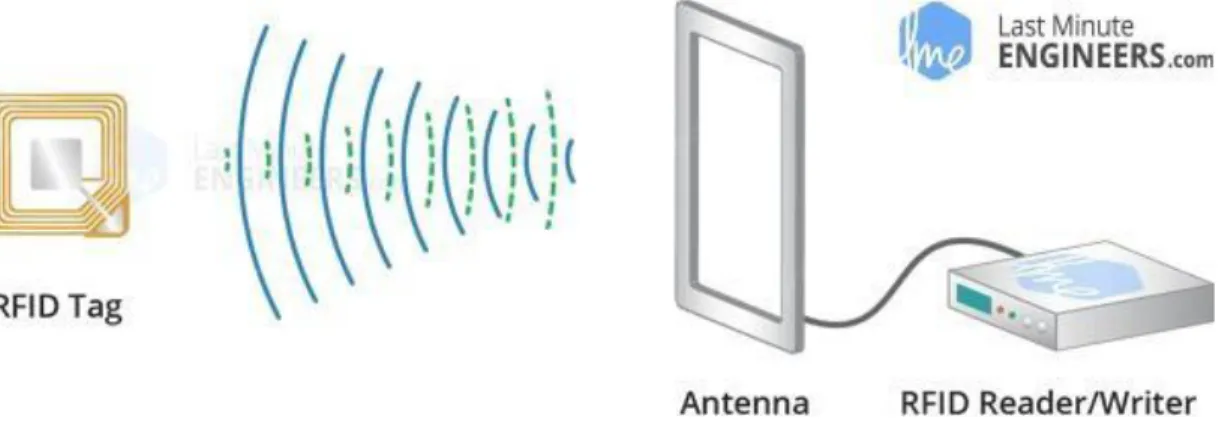
For recording student attendance and reading a specific student, this system uses an RFID tag and reader. The reader then establishes a connection with an Arduino microcontroller, which transmits the RFID reader's response to an Ib server using an Arduino shield.
Summary
By logging into this specific Ib-based program, the system administrator can access all students' documents.
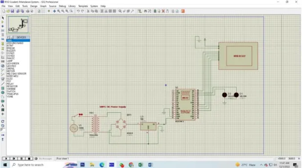
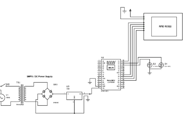
System Description
- Introduction
- System Description
- Block Diagram
- Circuit Diagram
- Working Principle
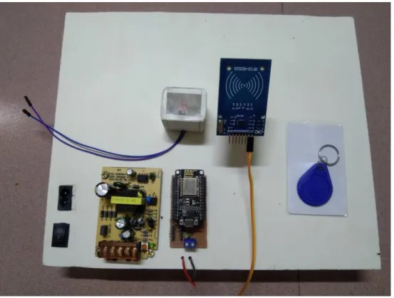
- Complete Project Image
- Summary
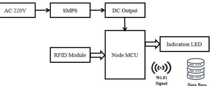
When a student enters an institute, they scan their RFID card and then their whole. Meanwhile, when they scan their card with RFID reader sensor, data will be stored in the database.
Hardware and Software
Introduction
About Hardware and Software
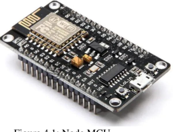
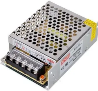
SMPS 2. Node MCU
- Hardware
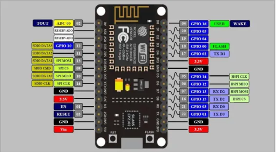
- Node MCU
Technically, "Node MCU" only refers to the firmware; the accompanying development kits are not included. The ESP8266 Espressif Non-OS SDK for ESP8266 was used to develop the microcode, which is supported by the eLua project. Users must select the components needed for their project and create a microcode specific to their needs due to resource limitations.
The fundamental support of the design was provided by the ESP-12 module of the ESP8266, a Wi-Fi SoC combined with a Tensilica Xtensa LX106 core and widely used in IoT applications. It has hardware based on the ESP-12 module and firmware running on the Express if Systems ESP8266 Wi-Fi SoC. Instead of the development kits, the expression "Node MCU" often refers to the firmware.
It is built using the Espress if Non-OS SDK for ESP8266 and is based on the eLua project. Widely used in Internet of Things applications, the ESP8266 is a Wi-Fi SoC combined with a Tensilica Xtensa LX106 core (see related projects). Hong released the initial version of the Node MCU firmware on GitHub on October 13, 2014, officially debuting the Node MCU.
The project was expanded to an open hardware platform two months after developer Huang R submitted a Gerber file for the devkit v0.9 ESP8266 board. Later that month, Tuan PM contributed to the Node MCU project and modified the Contiki MQTT client library for the ESP8266 SoC platform. Therefore, by using Lua to connect to the MQTT broker, the Node MCU could manage the MQTT IoT protocol.
Devsaurus ported the u8glibto Node MCU project on January 30, 2015, which enables Node MCU to quickly control LCD, Display, OLED, and even VGA displays. The firmware project's developers abandoned it in the summer of 2015, and a bunch of unrelated contributors took over. With just a few lines of Lua code using the Arduino IDE, the Node MCU V3 ESP8266.
Features
- Switch Mode Power Supply (SMPS)
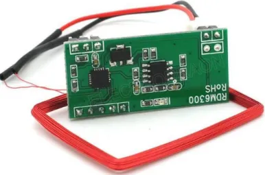
- RFID Module
- Capacitor
- Resistor
- Software
- Arduino IDE
- Proteus Software
- Summary
- Result and Discussion
- Introduction
- Result
- Advantages
- Applications
- Conclusion
- Conclusion
- Future Scope of Work
Due to the small size and lighter light of electrical equipment, switching power supplies can be significantly smaller and lighter than linear ones. The US can upload new code without the need for an additional PC hardware programmer, as the ATmega328 IC bootloader used in the Arduino Nano is pre-programmed. One of the most important fashionable digital microcontrollers is the Arduino Nano, which includes a wide range of communication options with a PC, another Arduino, or other microcontrollers.
Simple data will be sent to using a serial monitor which can be found in the Arduino code, obtained from the Arduino board. Any digital pin of the Nano can now support serial communication thanks to the code's serial storage. The Wildebeest toolchain and AVR work are used by the Arduino IDE to generate and transfer programs, so.
Thanks to the serial code library, serial communication is possible on any Nano digital connector. To facilitate the use of the I2C bus, the Arduino code uses the Wire library. The code used to build Arduino applications, called ideas, is written in C or C++. The Arduino IDE uses the gnu toolchain and the work of AVR to compile programs and subsequently download programs.
AVR Studio or the new Atmel Studio, Atmel's development environment, may also be used to producing code for the Arduino platform, as it uses Atmel microcontrollers. There is also the Arduino Software (IDE), also known as the Arduino Integrated Development Environment. To create computer programs known as sketches, one uses the Arduino software (IDE).
The terminal displays text generated by the Arduino Software (IDE), as additional information and detailed error warnings. The Arduino software (IDE) uses the concept of a sketchbook as a standard area to hold programs (or sketches). The Arduino application will automatically create a directory for your sketchbook when you first launch it.
When the upload is complete, the Arduino Software (IDE) displays a message or error message. If you name the subfolder 'Arduino' it will overwrite the Arduino platform that is already built in.
PLAGIARISM REPORT