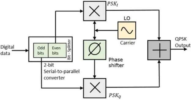
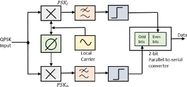
A renewed interest in optical communications was stimulated in the early 1960s with the invention of the laser. If the phase of the carrier (0) is varied in proportion to the information signal, phase shift keying (PSK) is produced.
Wavelength Division Multiplexing (WDM) 11
Channel/Connection is not divided based on frequency but based on time. In TDM, the data rate capacity of the transmission medium must be greater than the data rate required by the receiving equipment.
Polarization Division Multiplexing (PDM) 11
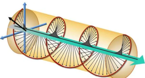
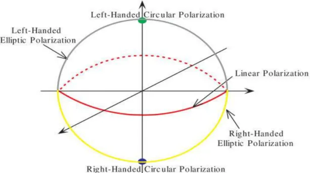
Indeed, any possible polarization can be written as a linear combination of left-handed and right-handed circularly polarized light. Circularly polarized light has angular momentume E k0 2 ˆ, with the positive sign for left-handed and the negative sign for right-handed. It is easy to understand because it is a sum of left and right handed light.
As an analogy, suppose you have two peaks, one rotating clockwise and one rotating counterclockwise, the two-peak system has no net angular momentum. It may seem surprising that photons, which are point-like particles without any substructure, can have angular momentum on their own. In this case, the refractive index of the two materials involved (air and sea, for example) plays a role, and the angle is not exactly 90 degrees.
Performance of Communication Link 15
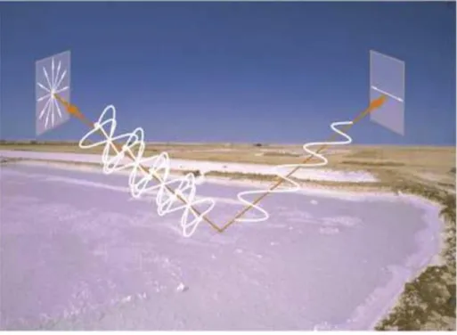
So for example, if you are on a boat and light is coming in from the sky (not just the sky directly above you), and also from the water, only the light reflected off the water will be polarized. So if we put on polarizing sunglasses, you can filter out the reflected light and see the things around us more clearly. Bandwidth: Usually measured in bits/second is the maximum rate at which information can be transferred.
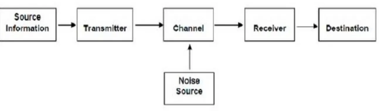
Latency: The delay between the sender and the receiver decoding it, this is mainly a function of the signals travel time and the processing time at all nodes. Bit Error Rate (BER): Error rate is the number of corrupted bits expressed as a percentage or fraction of the total number sent. SNR: Signal to noise ratio (SNR) is defined as the ratio of a signal's power to the strength of background noise (unwanted signal). Both signal and noise power must be measured at the same and equivalent points in a system, and within the same system bandwidth.
Cross Polarization (XPol) 17
Power Penalty 17
Receiver Sensitivity 18
For example, a receive sensitivity of -98 dBm is better than a receive sensitivity of -95 dBm times 3 dB or a factor of two. In other words, at a specified data rate, a receiver with a sensitivity of -98 dBm can hear signals that are half the power of those heard by a receiver with a receiver sensitivity of -95 dBm. The minimum acceptable value of received power needed to achieve an acceptable BER or performance.
Receiver sensitivity does not include power penalties associated with scattering or back reflections from the optical path; these effects are specified separately in the assignment of the maximum optical path penalty. Receiver sensitivity is more for an optical receiver when it achieves the same performance with less optical power on it. The three important factors that affect the sensitivity of receivers are bit error rate (BER), minimum received power, and photodetection quantum limit.
Coherent Homodyne Optical Transmission 19
Bit rate is defined as the probability of misidentification of a bit by the receiving decision circuit. With the direct detection, only the amplitude of the signal can be obtained, which loses its phase. Multilevel modulation formats with high spectral efficiency (SE) supported by advanced digital signal processing (DSP) and coherent detection made it possible to increase the data rates. Coherent receivers are sensitive to the phase and SOP of the incoming signal.
Until now it was assumed that the polarization of the incoming signal was always aligned with that of LO. However, in practical systems, the polarization of the incoming signal is unlikely to remain aligned with the polarization state (SOP) of LO due to random changes in the birefringence of the transmission fiber. One of the most serious problems of the coherent receiver is that the sensitivity of the receiver depends on the SOP of the incoming signal.
Circular Polarization Division Multiplexing (CPDM) 21
Crosstalk will be one of the main limitations for the CPDM system in optical networks. The procedure must be repeated for each pair of wires in the cable. Interestingly, most of the contributions on these topics are publications in IEEE, ICOE.
To analyze the expression of signal to crosstalk plus noise ratio (SCNR) at the output of a coherent homodyne QPSK receiver. Analysis is performed for the optically coherent homodyne CPDM-QPSK transmission system considering the influence of the SOPs. Analysis is presented to find out the expression of signal to crosstalk plus noise ratio (SCNR) and bit error rate (BER) at the output of the coherent homodyne QPSK receiver.
The coating used in the beam splitter is of great importance in reducing the dispersion and retardance of the incident light beam. Light whose polarization is in the direction of the optical axis sees an optical index ne (for "extraordinary"). 44 Fig. 2.9: Configuration of the coherent receiver that measures the lag between the signal and the LO.
According to the analytical approach presented in section III, signal power, noise power and XPol-induced crosstalk power at the output of the coherent homodyne CPDM-QPSK receiver are evaluated for a given average misalignment angle (θm).
Limitation of CPDM System 22
CPDM-QPSK Coherent Homodyne Transmission System 23
Given the bandwidth limitations imposed by optical amplifiers and ultimately by the fiber itself, it is important to maximize spectral efficiency, measured in bits/s/Hz. But given the limitations on signal power imposed by the nonlinearity of the fiber, it is also important to maximize the power efficiency (or SNR), i.e., to minimize the required average transmitted energy per bit (or the required signal-to-signal ratio -noise per bit).
Previous Work on CPDM-QPSK Coherent Homodyne
This paper is based on the theoretical understanding of polarization in light and therefore needs experimental validation.
Objectives of The Thesis Work 24
Organization of The Thesis 25
SYSTEM MODEL AND THEORETICAL ANALYSIS
Transmitter Components of The System Model 29
This is accomplished by placing or forming mirrors at both ends of the amplification medium. The beam combiner works on the same principle as a beam splitter, where part of the incident beam is reflected at 90°, while the rest is transmitted in the same direction. As a result, an unpolarized beam is obtained that has the combined optical power of the incoming beams (neglecting some parasitic losses) and the same beam quality.
Assuming equal input powers for the two ports, the output polarization will be rotated by 45° relative to the direction of polarization of either input beam. Beam splitters are typically designed for 0° or 45° angle of incidence with a 90° separation of the beams, depending on the configuration. But for beam directions that are not parallel to the optical axis, the polarization direction perpendicular to the polarization of the ordinary beam will be partially in the direction of the optical axis, and this is called an extraordinary beam.
Receiver Components of The System Model 40
Power dividers (also power splitters and, when used inversely, power combiners) and directional couplers are passive devices used primarily in the field of radio technology. An essential feature of directional couplers is that they only couple power flowing in one direction. Power entering the output port is connected to the isolated port but not to the coupled port.
Hybrid couplers are a special case of a four-port directional coupler that is designed for a 3-dB (equal) power split.
Theoretical Analysis 42
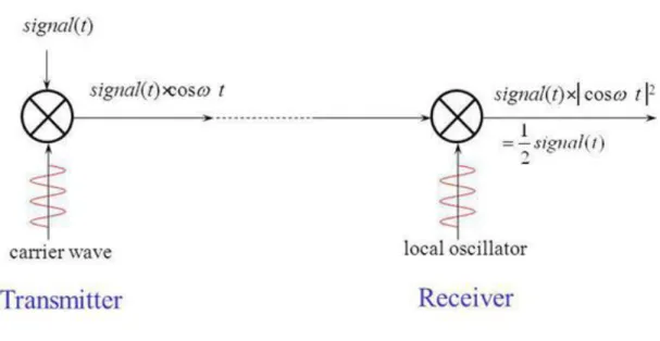
The basic concept behind coherent detection is to obtain the product of the electric fields of the modulated signal light and the continuous wave (CW) local oscillator (LO). We note here that the complex amplitudes AS and ALO are related to the signal power PS and the LO power PLO by PS = AS 2/ 2 and PLO = ALO2/ 2, respectively. Balanced detection is usually introduced into the coherent receiver as a means of suppressing dc component and to maximize the signal photocurrent.
The concept is to use a 3-dB optical coupler that adds a 180◦ phase shift to either the signal field or the LO field between the two output ports. Since there are random rotations of sub-channel SOPs, the PBS eigenmode of the receiver will be wrong, which causes signal fading and causes cross-talk between sub-channels. Taking the PBS eigenmodes, the electric field of the subchannel Ex will be the component of the main field along ex,.
RESULTS AND DISCUSSION
Analysis of SCNR (θ) and Received Signal Power (dBm) for
From the plots of SCNR(θ) vs. Received signal power for different misalignment angles (θ) shown in fig. 3.1, it is noted that there is a significant degradation of SCNR from 35dB to 0dB for increasing the misalignment angle from 0o to 90o at a given signal power of -20dBm (for example). It is observed that the SCNR is negative at a misalignment angle of 90 degrees, since the signal power is less than the total noise power.
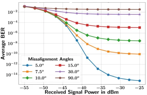
Analysis of BER (θ) and Received Signal Power (dBm) for
In Fig 3.3, average BER is plotted as a function of Received Signal Power for different misalignment angles using the Maxwell-Boltzman pdf on θ. It was found that at a given signal power -33 dBm and at local oscillator power 1.0mW the average BER increases from 10−14 to 10−1 for misalignment angles from 50 to 900. SO, BER is observed to increase with the increase in misalignment angle at a given signal power as misalignment angle increases Xtalk power.
From equations (2.33) and (2.34), it is clear that the BER performance decreases due to the increase in Xtalk power, which is remarkably satisfied by the plots of average BER versus received signal power. As the power of the local oscillator decreases from 10.0 mW to 0.1 mW, the received signal power increases to 26 dBm, from −45 dBm at that BER of 10−9. The signal power is constant at a given LO power when there is no crosstalk, and the signal power decreases with θ in the presence of crosstalk.