The report titled “Managing Peck and Place Robotics Arm With Robot Car Smartphone” was prepared to meet the requirements of our practicum program. A smartphone-operated robot is one technology in the manufacturing industry that is designed to perform pick-up and drop-off operations. The main goal of this project is "Smartphone Controls and Positions Robot Arm with Robot Car System" The project for The main purpose is to create a smart system so that we can get many benefits from one project.
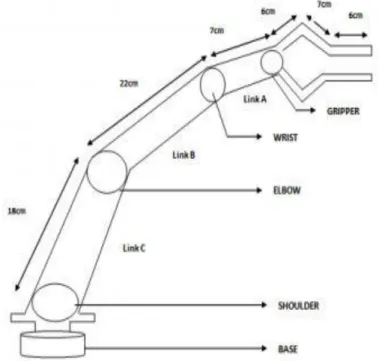
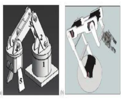
The name of our project is Smartphone Control Peck and Place Robotics Arm With Robot Car .It is a modern project. The links of such a manipulator are connected by joints that allow either rotational movement (as in an articulated robot) or translational (linear) displacement. The links of the manipulator can be thought of as a kinematic chain. The business end of the kinematic chain of the manipulator is called the end effector and it is analogous to the human hand.
The gripper of the robot is also made of aluminum for the same reason as the structure of the main robot arm. The mobile robot has a dimension of (28 x 15.5 x 8.5) cm, which is the length, width and height as shown in the picture :1.Acrylic is used as the main material for the mobile robot arm because it is easy to shape, it is cheap, strong and can handle the weight and movement of the engine. 3 servo motors and a servo wheel are attached to this system.
Methodology
Chapter Two
THEORETICAL BACKGROUND
- Introduction
- Literature Survey
- Android Application
- Hazardous duty
Android has a growing selection of third-party apps, which can be obtained by users by downloading and installing the app's APK (Android application package) file, or by downloading them using an app store program that allows users to install , update and remove apps from their devices. This code section handles the permissions that the app needs to get from the android app device or mobile phone. Since the app uses the Bluetooth feature of the device, it receives permission to use.
For example, the position of the buttons and their function are included in this section of the application coding. Typically, these robots look like small armored tanks and are remotely guided by personnel using video cameras attached to the front of the robot. Robotic arms can grab a suspected bomb and place it in a blast-proof vault for detonation and/or disposal. Similar robots can help clean up toxic waste.
Chapter Three
DESIGN AND DEVELOPMENT
- Introduction
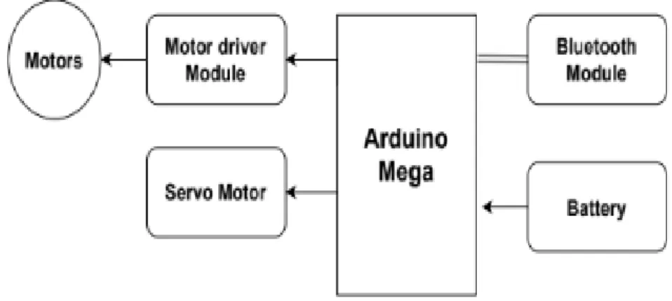
- Block Diagram of This Project
- Circuit Diagram of This Project
- Working Principle of Circuit Diagram
- The list of devices used in the project is given below
- Arduino MEGA
- Background
- History
- Hardware
- Software
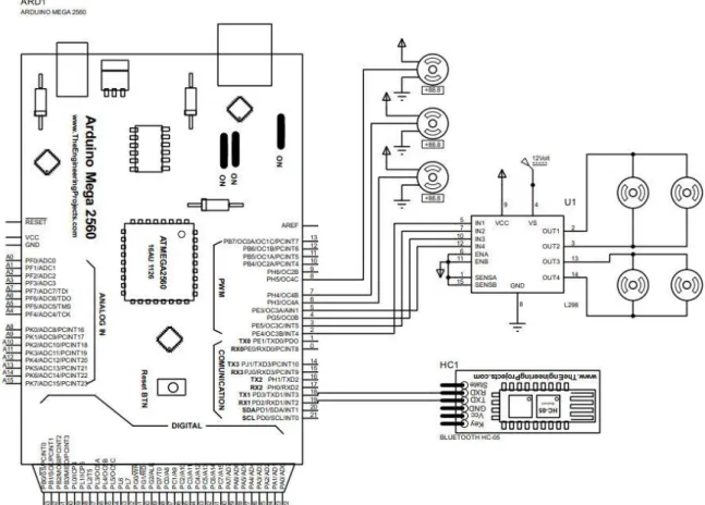
In this proposed system we have used Arduino MEGA development board and Bluetooth module. The arduino controller will control the motor drive module and the servo motor to execute the command. Early arduino boards used the FTDI USB-to-serial driver chip and the ATmega168. The Uno differed from all previous boards by the ATmega328P and ATmega16U2 (Atmega8U2 up to version R2) microcontroller programmed as a USB-serial converter.
The Arduino project was started at the Interaction Design Institute Ivrea (IDII) in Ivrea, Italy. At the time, students used a BASIC Stamp microcontroller at a cost of $50, a significant expense for many students. Around the same time, Massimo Banzi announced that the Arduino Foundation would be "a new beginning for Arduino." But a year later, the fund has still not been established and the status of the project remains unclear. Controversy surrounding Musto continued when, in July 2017, he reportedly pulled many open source licenses, schematics, and code from the Arduino website, sparking scrutiny and outcry.
The hardware reference designs are distributed under a Creative Commons Attribution Share-Alike 2.5 license and are available on the Arduino website. The official policy document on using the Arduino name emphasizes that the project is open to incorporating the work of others into the official product. Several Arduino-compatible products released commercially have avoided the project name by using different names ending in -duino. The default bootloader of Arduino UNO is optiboot bootloader. Boards are loaded with program code via a serial connection to another computer.
Other variants, such as the Arduino Mini and the unofficial Boarduino, use a detachable USB-to-serial adapter board or cable, Bluetooth, or other methods. When used with traditional microcontroller tools, standard AVR In-System Programming (ISP) programming is used instead of the Arduino IDE. The Arduino Nano and Arduino compatible Bare Bones Board and Boarduino boards can have male header pins on the bottom of the board that can be connected to solderless breadboards.
1.1.1 3.5.5 Integrated Development Environment
Diecimila, Duemilanove and the current Uno offer 14 digital I/O pins, six of which can produce pulse-width modulated signals, and six analog inputs that can also be used as six digital I/O pins. Many improve the basic Arduino by adding output drivers, often for use in school education, to simplify the construction of carts and small robots.
1.1.2 3.5.6 Sketch
Blink example
Most Arduino boards contain a light emitting diode (LED) and a current limiting resistor connected between pin 13 and ground, which is a convenient feature for many tests and program functions. A typical program used by beginners, similar to Hello, World!, is "blink", which repeatedly blinks the on-board LED built into the Arduino board. This program uses the pinMode(), digitalWrite(), and delay() functions, which are provided by internal libraries included in the IDE environment.
1.1.3 3.5.8 Technical Specifications
- Applications
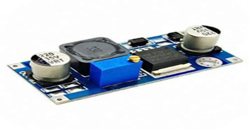
- Buck Module
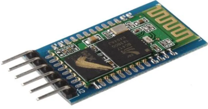
- Bluetooth Module
- Introduction
- Specification
- Pin Description
- Test method
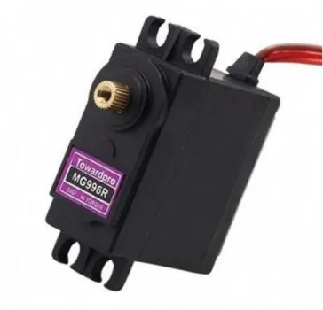
- Servo Motor
- Specification
- Gear Motor
- Gear Motor Work
- Gear Motors and Increased Force
- Lipo Battery
- Features
- Specifications
- Application
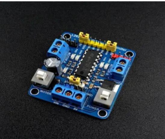
- Motor Driver module
- Specifications
- Pin Description
- Hardware & Software Requiewd
Gear motors can be found in many different applications and are likely used in many appliances in your home. A geared motor can be an AC (alternating current) or DC (direct current) electric motor. As a general rule, the longer the gear train, the lower the power of the final or final gear.
However, a series of reduction gears is used to slow down the movement of the hands on the clock. This is what allows the second hand to make one complete revolution per minute on the face of the watch. Gear motors are commonly used in commercial applications where a piece of equipment must be able to exert a large amount of force to move a very heavy object.
As you have probably noticed, a crane can be used to lift and move very heavy objects. The electric motor used in most cranes is a type of geared motor that uses the basic principles of speed reduction to increase torque or power. But the principles of the gear motor used in a crane are exactly the same as those used in the electric clock example.
The output speed of the rotor is reduced through a series of large gears until the rotational speed, RPM, of the final gear is very low. The low rotational speed helps to create a high amount of force that can be used to lift and move the heavy objects. Two enable inputs are provided to enable or disable the device independently of the input signals. The emitters of the lower transistors of each bridge are connected to each other, and the corresponding external terminal can be used to connect an external sensing resistor.
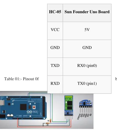
1.1.4 3.11.4 Hardware Connections
Features
List of Components With Price
Chapter Four
SOFTWARE AND SIMULATION
- Introduction
- Software Tools
- Programming
- Arduino Program Development
- Proteus8.1
The software part is one of the most important parts of the MCU based single phase induction motor drive, control and protection system. The software used to program the microcontroller is open source software and can be downloaded for free at www.arduino.cc. Now the Arduino software and the USB driver for the board must be installed in sequence.
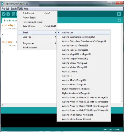
We downloaded the Arduino software from www.arduino.cc and installed it on the computer (it was NOT connected to the PC). The board we want to connect must be selected on the arduino software. We must select the correct "Serial-Port", to let the computer know which port the card has been connected to.
The amount of ports shown does not depend on the number of USB ports on the computer. Code execution: The Arduino sketch is executed as soon as it finishes the step of uploading to the board. You can simulate your microcontroller programming in Proteus 8 Simulation Software. After simulating your circuit in Proteus 8 Software, you can directly make PCB designs with it, so it could be an all-in-one package for students and hobbyists.
This program allows users to interact with the design using on-screen indicators and/or LED and LCD displays and, if connected to the PC, switches and buttons. One of the main components of Proteus 7.0 is Circuit Simulation - a product that uses a SPICE3f5 analog simulator core combined with an event-driven digital simulator that allows users to use any SPICE model by any manufacturer. Proteus VSM comes with extensive debugging features, including breakpoints, single step and variable display for neat design before hardware prototyping. In summary, Proteus 7.0 is the program to use when you want to simulate the interaction between software running on a microcontroller and any analog or digital electronic device connected to it.
Chapter Five
RESULT AND OUTPUT OBSERVATIONS
- Introduction
- Working Principle of this Project
- Result
After booting, the project will start. The mobile module must be connected to the Bluetooth module in the project. We have robots made from smartphone apps. It can be easily taken to the place we want with just the command of the smartphone. Robot arm robotics that can transfer any product under the command of a mobile phone.
Chapter Six
CONCLUSION AND DISCUSSION
- Conclusions
- Advantages
- Applications
- Limitation
- Future works
It can also be applied in small industries because saving energy and paying fines cause a major problem in the whole scale industry and this method corrects the whole problem and thus it will be an obligation to minimize their expenses. This will be the best solution in the future, because human power will completely disappear and be automated. This will play a big role in it. IOT based monitoring and control system can be implemented, this will allow the use of advanced sensors such as color detector sensors and include mobile system.
9] https://play.google.com/store/apps/details id=com.gundel.bluecontrol&hl=en .April 2015.
APPENDIX
Program