The research that led to this thesis was done when we were civil engineering students at Daffodil International University in Dhaka, Bangladesh. First of all, we would like to express our gratitude to our supervisors for not only giving us the opportunity to pursue our studies as thesis students at Daffodil International University, but also for always being supportive and patient with us. Especially for the right guidance and support, as well as for sharing their great expertise with us and patiently answering our questions.
The thesis "DETAILED ANALYSIS BY ETABS OF A 530 SQUARE METERS RESIDENTIAL BUILDING LOCATED IN DHAKA" was completed under the supervision of Mardia Mumtaz, (lecturer) Department of Civil Engineering, Daffodil International University, Dhaka, Bangladesh, and was partially approved. the requirement for the Bachelor of Science in Civil Engineering. First of all, we would like to express our gratitude to our Creator for allowing us to complete the Thesis Project. Faysal, Assistant Professor, Department of Civil Engineering, DIU, is one of our mentors, and we are ecstatic to convey our utmost thanks, kindness, respect and gratitude to him.
Arifa Akhter, Lecturer, Department of Civil Engineering, DIU, and Mardia Mumtaz, Lecturer, Department of Civil Engineering, DIU, for their selfless help, individual guidance, excellent teaching, advice, encouragement, helpful advice and kindness in helping me with this research. also thanked dr. Mohammad Hannan Mahmud Khan, Assistant Professor and Head of the Department of Civil Engineering, as well as all the faculty and staff of Daffodil International University. We would also like to thank our classmates and friends for sharing their knowledge and information with us and helping us complete the research.
This report is compiled as "ETABS DETAILED ANALYSIS OF A 530 SQUARE METERS RESIDENTIAL BUILDING LOCATED IN DHAKA". This six storied residential structure is an RCC structure.
Introduction
- Introduction
- Background of the Study
- Objective
- Scope of study
- limitations
According to the BNBC definition, a low-rise building is any building whose height is less than 20 meters. A medium-rise building is one whose top level does not exceed 70 feet and does not exceed 75 feet, with a maximum height of 8 stories. Any building whose top level exceeds 70 feet or 75 feet, often more than 8 stories, is classified as a tall building. The structural design of the structure is generally made taking into account seismic and wind loads.
Studying and comparing the effects of lateral forces on a residential structure using ETABS software. Acquire basic knowledge of how to use basic ETABS software to design concrete buildings. Use of ETABS software to study and compare the effects of lateral force on a residential structure.
The overall objective of this research is to use ETABS software to construct a given structure and analyze variations in building capacity. Because the BNBC 1993 code was used, the study may be outdated and outdated software was used to comply with the BNBC 1993 code suggestions.
Review of literature
- RCC Frame Structure
- Dead Loads
- Live Loads
- Floor Live Loads
- Wind Loads
- Earthquake Loads
The weight of all materials, suspended loads (such as sanitary and electrical fixtures, linings and fixtures), and permanent equipment included in the building or other structure are all included. Permanent loads are a broader category that includes dead loads as well as force induced by irreversible changes in structures over time, such as settlement, secondary effects of prestressing, shrinkage and creep burning. Walls, floors, ceilings, stairs, built-in partitions, finishes, cladding and other similar architectural and structural components, as well as the weight of cranes, are all examples of dead load.
A live load is an expression used in civil engineering to describe a load that can vary over time. When people move around in a building, the weight of the load is variable or the position varies. Because it can be moved anywhere, anything in a building that is not attached to the structure can result in a live load.
Thus, live loads are the maximum loads predicted for occupancy by the intended use, although they should never be less than the loads specified in this section. These loads shall be considered the minimum loads in pounds per square foot of horizontal rejection to be used in the design of buildings for the specified occupancies, and loads at least equal shall be assumed for uses not specified in this section, but those similar loads. In the design of such a building or parts thereof, use should be made of the actual load when it can be determined in the design of floors that the actual load will be greater than the value.
Every building or structure, and every component thereof, shall be constructed and constructed to withstand the wind effects determined in accordance with this section's criteria. The shielding effect of nearby structures will not result in any reduction in wind pressure. Buildings sensitive to dynamic effects, such as those with a height-to-width ratio greater than five, structures particularly vulnerable to wind-induced oscillations, such as vortex shedding or icing, and structures over 400 feet (121.9 m ) in height, shall be designed in accordance with approved government standards, and all structures shall be designed in accordance with approved national standards. Building and foundation systems in areas prone to erosion and water pressure due to wind and wave action are exempt from the restrictions of this section.
Buildings and foundations exposed to such loads must be designed in accordance with authorized national standards. As a minimum, the structure and its components shall be constructed and constructed to withstand the impact of seismic ground motions as specified in this section.
Methodology
General
Flow chart
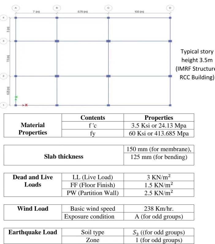
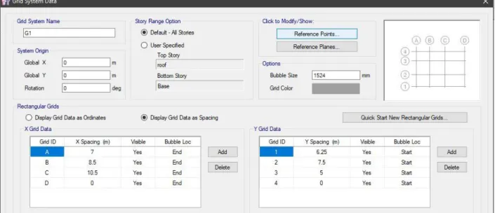
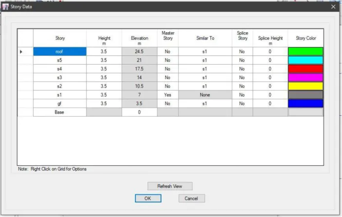
Input Data
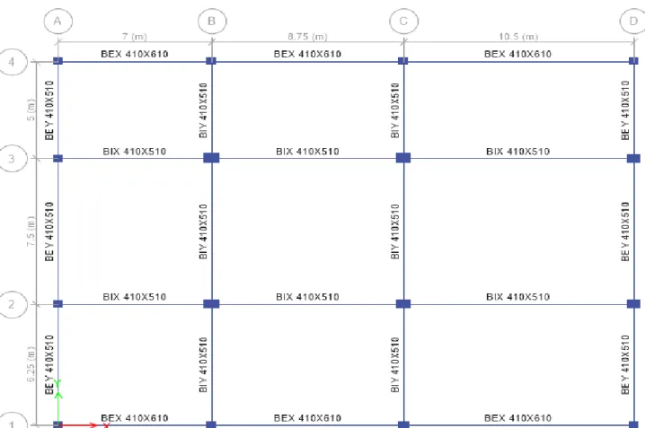
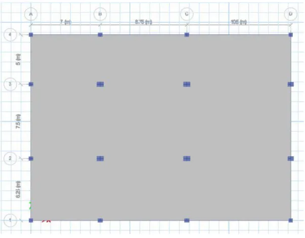
Column Layout
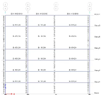
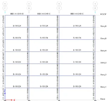
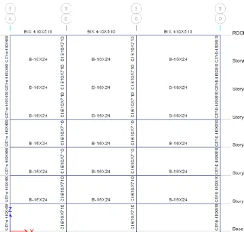
Beam Layout
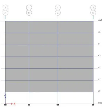
ETABS Modeling
Overview
ETABS Modeling
Wind Load
BNBC 1993 Code
Input Data
Calculations
Back Calculations
Detailed view of the calculations
Earthquake Load
BNBC 1993 Code
Value of Ct for Method A
Input Data
ETABS data input
Chapter–8 Analysis Data
Slab Moment
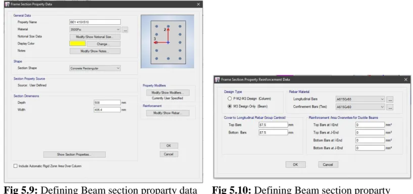
Beam Longitudinal Reinforcement
Column Reaction
Column Analysis Data
Conclusion & Recommendation