First of all, we express our sincere thanks and gratitude to Almighty Allah for His divine blessings which enabled the successful completion of this project. In summary, this project proposed and then solved several transmission line resource allocation problems.
Overview
Microwave
Microwave sources
Radio frequency
Communication
- Radio communication
- Line of sight communication
- Radar
- Navigation
Metropolitan networks: MAN protocols such as WiMAX (Worldwide Interoperability for Microwave Access) based on the IEEE 802.16 specification. Most satellite communication systems operate in the C, X, Ka or Ku bands of the microwave spectrum.
Special properties of RF electrical signals
In the vapor phase, isolated water molecules absorb at about 22 GHz, almost ten times the frequency of the microwave.
Cellular network
GSM History
This is done by providing functional and interface descriptions for each of the functional entities defined in the system. The United States did not suffer from a variety of incompatible systems as in the various countries of Europe.
What is GSM
The Base Transceiver Station (BTS)
The BTS contains the radio transceiver that defines a cell and handles the radio connection protocols with the MS. The BTS corresponds to the transceivers and antennas used in each cell of the network.
The Base Station Controller (BSC)
GSM frequency bands
Signal strength
Bandwidth
Bandwidth (signal processing) or analog bandwidth, frequency bandwidth or radio bandwidth: a measure of the width of a range of frequencies, measured in hertz. Spectral linewidth the width of an atomic or molecular spectral line, measured in hertz.
Introduction
Transmission Line
Basic Principles of Transmission lines
Distributed parameters
Types of Transmission Lines
Open Wire Line
Twisted Pair Line
The different types of twisted pair cables include stressed twisted pair, unstressed twisted pair, bonded twisted pair and twisted ribbon cables.
Unshielded Twisted Pair
Primary Constants of TL
Introduction
Parameters
- Resonant frequency
- Antenna Gain
- Radiation pattern
- Impedance
- Efficiency
- Gain
- Beamwidth
- Bandwidth
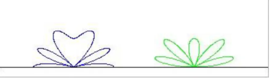
Low-gain antennas have shorter ranges, but antenna orientation is relatively unimportant. The radiation pattern of an antenna is the geometric pattern of the relative field strength of the field emitted by the antenna. The radiation pattern of an antenna is typically represented by a three-dimensional plot, or polar plots of horizontal and vertical cross sections.
Efficiency is the ratio of power actually radiated to the power put into the antenna terminals. A is the area of the antenna aperture, i.e. the mouth of the parabolic reflector.
Polarization
Obviously, parabolic antennas can produce very narrow beams, and aiming them can be a problem. An antenna's bandwidth is the frequency range over which it is effective, usually centered around its resonant frequency. They also have a negative effect on the rejection of unwanted harmonics, both on received and transmitted signal frequencies.
For line-of-sight communications that rely on polarization, there can be a big difference in signal quality if the transmitter and receiver use the same polarization; we often see a difference of several tens of dB, and this is more than enough to make the difference between reasonable communication and a broken connection. The radiation is greatest perpendicular to the dipole, it drops to zero on the axis of the antenna.
Transmission and reception
Effect of ground
Most of the electromagnetic waves emitted by an antenna to the ground below the antenna at moderate (say < 60°) angles of incidence enter the earth and are absorbed (lost). This means that the receptor "sees" the actual antenna and below the ground the image of the antenna reflected by the ground. The situation is a bit more complex because the reflection of electromagnetic waves depends on the polarization of the incident wave.
Since the refractive index of the ground (average value ) is greater than the refractive index of air ( ), the direction of the component of the electric field parallel to the ground is reversed upon reflection. If some elements are not powered (there is a short circuit instead of a power cable), as in the case of TV antennas (Yagi-Uda antennas), they are the corresponding zero.
Types of Antenna
- Parabolic antenna
- Dipole antenna
- Dipole characteristics
- Directional antenna
- Omni directional antenna
Dipoles that are much smaller than the wavelength of the signal are called Hertzian, short, or infinitesimal dipoles. Dipoles whose length is half the wavelength of the signal are called half-wave dipoles and are more efficient. This is because the impedance of the dipole is pure resistive at approximately this length.
The length of the dipole antenna is about 95% of half a wavelength at the speed of light in free space. Omni-directional antennas that are vertically oriented are widely used for non-directional antennas on the surface of the Earth because they radiate equally in all horizontal directions, while the power radiated decreases with elevation angle, so that little radio energy in the air or directed downwards to the earth and wasted. .
Antenna aperture
A directional antenna or beam antenna is an antenna that emits more power in one or more directions, allowing for increased transmission and reception performance and reduced interference from unwanted sources. Directional antennas such as yagi antennas provide increased performance compared to dipole antennas when a greater concentration of radiation in a specific direction is desired. An omnidirectional antenna is an antenna that emits power uniformly in one plane, where the radiated power decreases with the elevation angle above or below the plane, and falls to zero on the axis of the antenna.
In general, antenna gain is increased by directing radiation in a single direction, while it is necessarily reduced in all other directions, since current cannot be created by the antenna. Large parabolic antennas, many wavelengths across, have an aperture nearly equal to their physical range.
Antenna effective area
Feeder line
When a balanced antenna, such as a dipole, is fed by an unbalanced feeder, the normal currents can cause the coaxial line next to the antenna itself to radiate, and the radiation pattern can be asymmetrically distorted.
Calculation of Antenna parameters in reception
The equivalent circuit and formula on the right are valid for any type of antenna. It can also be a dipole antenna, a magnetic loop, a parabolic antenna or an antenna array. The maximum power an antenna can extract from an electromagnetic field depends only on the gain of the antenna and the squared wavelength.
Using the equivalent circuit, it can be shown that the maximum power is absorbed by the antenna when it is terminated with a load matching the input impedance of the antenna. This also implies that under matched conditions, the amount of power re-radiated by the receiving antenna is equal to that absorbed.
Introduction
Fresnel zone
Fresnel zone formula
Free-space path loss
Free-space path loss formula
This equation is correct only in the far field where spherical propagation can be assumed; does not hold close to the transmitter.
Line-of-sight propagation
Effective Isotropic Radiated Power (EIRP)
EIRP = Effective Isotropic Radiated Power Pout = transmitter power (dBm) Ct = signal loss in cable (dB). Otherwise, you must adjust either the transmitter power, the cable length and/or the choice of antenna.
Receiver Sensitivity
Signal to noise ratio
If the input signal strength in microvolts is Vs and the noise level, also in microvolts, is Vn, then the signal-to-noise ratio, S/N, in decibels is given by the formula. In this situation, the signal borders on unreadable because the noise level competes hard with it. In digital communications, this is likely to cause a reduction in data rate due to frequent errors that require the source (transmitting) computer or terminal to resend some data packets.
In this type of situation, reliable communication is generally not possible unless steps are taken to increase the signal level and/or reduce the noise level at the destination (receiving) computer or terminal.
Interference (wave propagation)
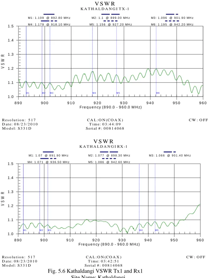
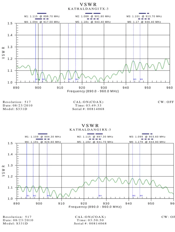
The voltage standing wave ratio (VSWR) is the ratio of the maximum voltage to the minimum voltage in the standing wave on a transmission line. As VSWR approaches 1.00:1, line reflections approach zero and maximum power can be transmitted. Within a typical base station antenna, the line impedance is changed at many places in order to spread the RF energy across the aperture.
Antenna engineers design matching sections in the antenna to minimize the overall impedance change (and associated reflections) relative to a 50 ohm reference. Measuring the VSWR of the antenna indicates how closely the antenna is matched to an impedance of 50 ohms and indicates the magnitude of reflected energy[8].
How is VSWR measured
Finding a proper location to test base station antennas
Measuring the antenna's VSWR indicates how closely the antenna matches the 50 ohm impedance and indicates the amount of reflected energy.[8] .. the antenna is placed against a wall with RF absorbing material. The RF absorber dissipates the energy radiated from the antenna and prevents reflections off the antenna from returning to the measurement.[5].
Test the antenna
Analysis
Understanding the Distance-to-Fault Measurement
Introduction
Distance-to-Fault
If the VSWR is more than the practical value, it will cause the fault, then you need to find out where in a transmission line VSWR is more than the practical value of 2. So VSWR was less than the practical value and there was no fault in the transmission line . If a 60 meter transmission line gets a VSWR of 2 or more than 2 at a 55 meter point, understand that DTF occurs at a 55 meter point.
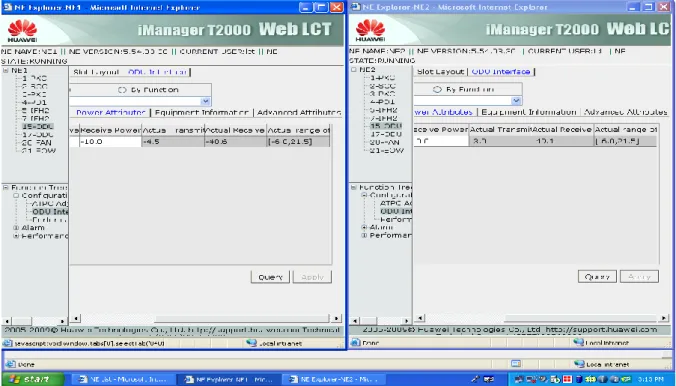
What is RSL
Link Budget
MFAS RAI 0 ALARM INDICATOR 0 SECONDS WITH LOSS OF SIGNAL 0 SECONDS WITH LOSS OF FRAMES 0 SECONDS WITH LOSS OF SYNC 0.
Analysis
One of the most crucial parts of a microwave link is the transmission line. We must always consider the loss factors that take place in the transmission line while measuring the performance of a microwave communication link. In this project, we performed an analysis to measure the performance of a microwave transmission line. After conducting the experiment on VSWR it is found that the location of Ranigonj and Kathaldangi, Tx and Rx will be very good if the practical value is less than 1.35 then the signal level will also be good.
Again from the test on DTF it is found that if the VSWR is more than the practical value then there is definitely fault in the transmission line and we need to find out the location of the fault. If a 60 meter transmission line gets VSWR of 2 or more than 2 at the 55 meter point, understand that DTF occurs at a distance of 55 meters.
Fig.1 Frequency Spectrum
Fig.1.2 Connection between BSS to MSC
Fig.1.3 Radio link between the BTS and MS
Fig. 2.1 Transmission Line
Fig.2.2 Sending and Receiving Terminal
Fig 3.1 Real antenna picture
Fig. 3.2 Radiation pattern
Fig. 3.5 Radiation patterns of antennas and their
Fig.3.6 Mutual impedance and interaction between antennas
Fig.4.1 Fresnel zones result from diffraction by the circular aperture
Fig.4.2 Gain of Isotropic and Practical antenna
Fig. 5.1 Site Master, Antenna, Jumper Cable and Connector
Fig.5.2 Ranigonj VSWR Tx1 and Rx1
Fig. 5.3:Ranigonj VSWR Tx2
Fig. 5.9 Ranigonj DTF Tx1 and Rx1
Fig. 5.10 Ranigonj DTF Tx2 and Rx2
Fig. 5.11 Ranigonj DTF Tx3 and Rx3
Fig.5.12 RSL PRINT SCREEN