The aim of the project is to design a transformer protection using microcontroller based relay and monitoring using IoT. The system would also provide real-time monitoring of transformer parameters. The system will also provide real-time monitoring of transformer parameters like voltage, current, temperature, etc. on the Android device and personal computers and get notifications in case of failure.
Problem Statement
The microcontroller-based relay provides more adjustable characteristics, high accuracy, more flexibility, increased setting range and reduced size, minimal cost with many functions such as self-monitoring and control with GSM technology.
Project Keywords
Objectives
Methodology
Organization of the Book
Literature Review
Literature Review
On the distribution side of the line, digital relays were used to solve specific protection and control problems. Several methods have been used, such as the per-phase method, the cross-blocking method, the percentage average blocking method, and the harmonic division method. IoT is now used almost everywhere and industries are booming because of IOT.
Equipment and Software Details
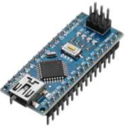
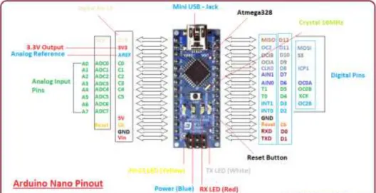
Arduino Nano
The Nano has the ability to fit a boarding and minibus with a smaller footprint than both, so users have more boarding space. It has a pin layout that works well with a Mini or Basic Stamp (TX, RX, ATN and GND on one top, power and ground on the other). One of the best features of the Arduino Nano is that it is easy to use, compact and also small.
Specifications
Features
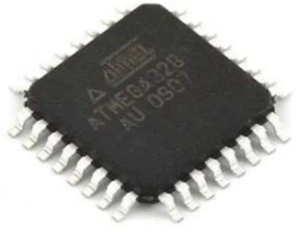
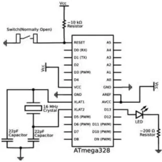
Microcontroller IC ATmega328p
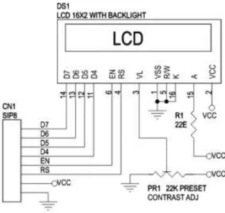
- LCD Display
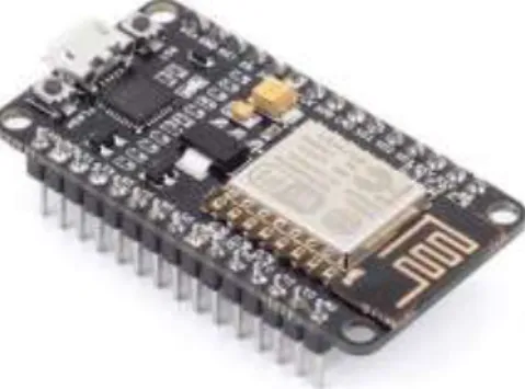
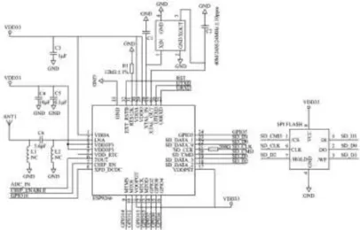
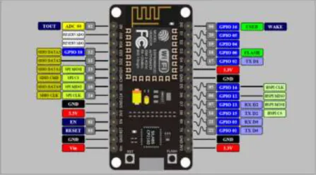
- Node MCU
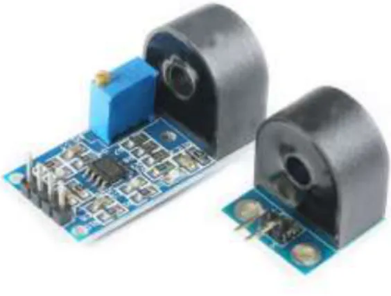
- Current Sensor
- Voltage Sensor
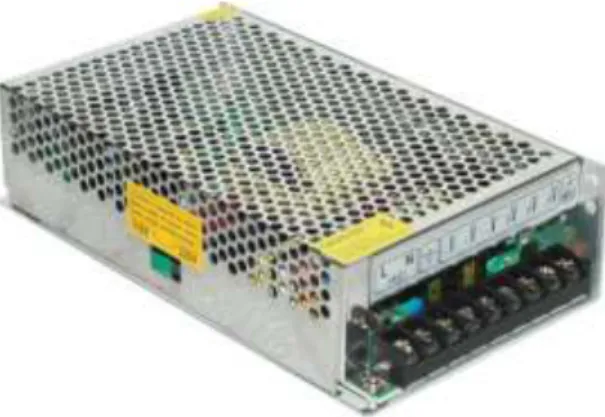
- SMPS
- Ultrasonic Sensor
LCD (Liquid Crystal Display) screen is an electronic display module and find a wide range of applications. Node MCU is an open source firmware for which open source prototyping board designs are available. The term "Node MCU" strictly refers to the firmware rather than the associated development kits.
The firmware is based on the eLua project and built on the Espressif Non-OS SDK for ESP8266. By default, the term "Node MCU" refers to the firmware rather than the development kits. It is based on the eLua project and built on the Espress if Non-OS SDK for ESP8266.
It is an ideal choice for measuring AC voltage using Arduino /ESP8266 /Raspberry Pi as an open source platform. A switching power supply is an electronic power supply that includes a switching regulator for efficient conversion of electricity. A switching power supply (switching power supply, switching power supply, switching power supply, SMPS or switch) is an electronic power supply that incorporates a switching regulator for efficient conversion of electricity.
Ultrasonic waves travel faster than the speed of audible sound (that is, the sound that humans can hear).
HC-SR04 Ultrasonic Sensor - Working
Unlike a linear power supply, the pass transistor of a switch-mode power supply continuously switches between low-dissipation, full-on, and full-off states and spends very little time in high-dissipation transitions, minimizing wasted energy. In contrast, a linear power supply regulates the output voltage by continuously draining power in the pass transistor. Switch-mode power supplies can also be significantly smaller and lighter than linear power supplies due to the smaller size and weight of the transformer.
An ultrasonic sensor is an electronic device that measures the distance of a target object by emitting ultrasonic sound waves, and converts the reflected sound into an electrical signal. The ultrasonic transmitter sends an ultrasonic wave, this wave travels in the air and when it is obstructed by any material, it is reflected back to the sensor, this reflected wave is detected by the Ultrasonic receiver module as shown in the picture below. Now, to calculate the distance using the formulas above, we need to know the speed and time.
Since we use the ultrasonic wave, we know the universal speed of the American wave at room conditions, which is 330 m/s. The circuitry built into the module calculates the time it takes for the US wave to come back and turns the echo pin high for that same amount of time. This way we can also know how long it takes.
How to use the HC-SR04 Ultrasonic Sensor
The amount of time the Echo pin remains high is measured by the MCU/MPU as it provides information on the time it takes for the wave to travel back to the sensor. It is used for obstacle avoidance and detection by robots such as biped robot, obstacle avoidance robot, wayfinding robot, etc. The depth of certain places like wells, caves, etc. can be measured as the waves can penetrate the water.
Ultrasonic Sensor Pin Configuration
MQ2 Smoke Detector Module
APPLICATIONS
This is a very user-friendly, low-cost semiconductor gas sensor module with analog and digital output.
Connection mode
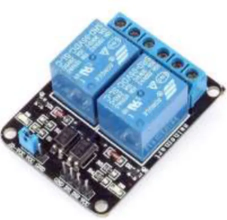
Relay
The first relays were used in long-distance telegraph circuits as amplifiers: they repeated the signal coming in from one circuit and retransmitted it on another circuit. Solid-state relays control power circuits without moving parts, but instead use a semiconductor device to perform switching. Magnetic latch relays require one pulse of coil power to move their contacts in one direction, and another, relay pulse to move them back.
Magnetic latching relays are useful in applications where intermittent power must not be able to pass through the contacts. In a single coil device, the relay will operate in one direction when power is applied with one polarity and will reset when the polarity is reversed. NO (Normally Open): there is no contact between the common pin and the normally open pin.
So, when you activate the relay, it is connected to the COM pin and supply is provided to a load. NC (normally closed): there is contact between the common pin and the normally closed pin. There is always connection between the COM and NC pins, even when the relay is turned off.
When you activate the relay, the circuit is opened and no supply is provided to a load.
Temperature Sensor
IN2: controls the second relay (must be connected to the Arduino digital connector if.
3.11 5V Regulator IC
Arduino IDE
The digital microcontroller device called Arduino Nano can be programmed with the Arduino software IDE. The IC used named as ATmega328 on the Arduino Nano is burned with a boot loader that allows us to upload new code to it without the use of an external hardware programmer. On Rev1 cards: connecting the solder jumper on the back of the card (near the map of Italy) and resetting 8U2.
The Arduino Nano is one of the latest digital microcontroller units and features a number. An ATmega16U2 on the board channels this serial communication over USB and appears as a virtual com port for software on the computer. The Arduino software includes a serial monitor that allows simple textual data to be sent to and from the Arduino board.
The Arduino IDE uses the GNU toolchain and AVR Lab to compile programs, and upload the programs it uses. Because the Arduino platform uses Atmel microcontrollers, Atmel's development environment, AVR Studio or the newer Atmel Studio, can also be used to develop software for the Arduino. The Arduino Integrated Development Environment - or Arduino Software (IDE) - contains a text editor for writing code, a message area, a text console, a toolbar with buttons for common functions, and a series of menus.
It connects to Arduino and Genuino hardware to load programs and communicate with them.
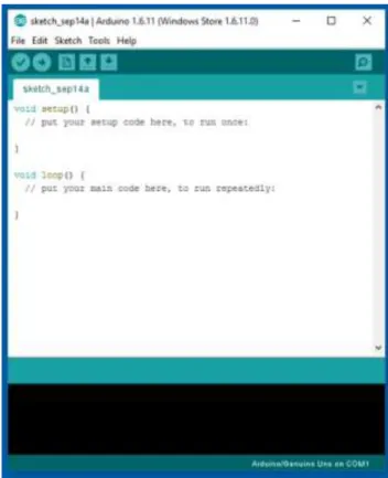
Writing Sketches
Proteus Software
The Proteus Design Suite is a proprietary software tool suite primarily used for electronic design automation. The first version of what is now the Proteus Design Suite was called PC-B and was written in 1988 by company president John Jameson for DOS. Mixed-mode SPICE Simulation was first integrated into Proteus in 1996 and microcontroller simulation then arrived in Proteus in 1998.
Shape-based automatic routing was added in 2002, and 2006 saw another major product update with 3D Board Visualization. More recently, a dedicated IDE for simulation was added in 2011, and MCAD import/export was included in 2015.
Remote XY
Distinctive features
Supported connection methods
Supported boards
Supported communication modules
Supported mobile OS
Remote XY allows
System Construction
- System Description
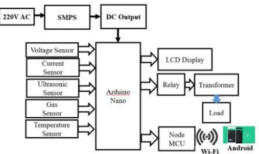
- Block Diagram
- Circuit Diagram
- Working Principle
- The Project Prototype
- Results
- Cost Analysis
- Conclusion
- Advantages
- Applications
- Future Scope of Work
- Conclusion
The schematic diagram here represents the electrical circuit and components of the hybrid power generation system. The power portion of this circuit consists of a 220V alternating current from the mains supply that is scaled down to 12V by the SMPS (Switch Mood Power Supply). The voltage is regulated using a voltage regulator down to 5V which supplies power to the rest of the circuit.
Here we also use voltage sensor, current sensor, ultrasonic sensor, gas sensor, temperature sensor etc. The temperature sensor measures the oil temperature of the transformer, the current and voltage sensor measures the current and voltage part of the transformer, and the ultrasonic sensor measures the amount of oil in the transformer. When the system is turned on, it measures the oil temperature of the transformer and the oil condition.
We are considering adding many features to our project in the future to get more desirable outcomes. Details about the transformer are automatically updated on the web page and notify when the transformer is in abnormal condition. We have described a remote monitoring system for distribution transformers using the existing IoT, which has low investment and operating costs.
Barhate, "Microcontroller based differential relay using fuzzy logic for transformer protection International Conference on Intelligent Computing and Control Systems (ICICCS), Madurai, 2017, pp. Barhate, "Transformer protection by distinguishing inrush and fault current with harmonic analysis using fuzzy logic IEEE International Conference on Control and Robotics Engineering (ICCRE), Singapore, 2016, pp. Fumagalli, "Internet of Things Security - Multilayered Method For End to End Data Communications Over Cellular Networks IEEE 5th World Forum on Internet of Things (WF-IoT), Limerick, Ireland, 2019, pp.
34; Monitoring and control system of transformer temperature rising test." In 2011 International Conference on Electrical and Control Engineering, pp.
Appendix