UNIVERSITI TEKNIKAL MALAYSIA MELAKA
LIFTING MECHANISM FOR AN AUTONOMOUS LINE
TRACKING ROBOT
This report submitted in accordance with requirement of the Universiti Teknikal Malaysia Melaka (UTeM) for the Bachelor Degree of Manufacturing Engineering
(Robotic and Automation) with Honours
by
NORRIS EZWAN BIN MOHAMAD NOR
Alamat Tet ap:
Tarikh: ____26 MAY 2009____
** Jika Laporan PSM ini SULIT at au TERHAD, sil a lampirkan surat daripada pihak berkuasa/ organisasi berkenaan dengan menyat akan sekal i sebab dan t empoh l aporan PSM ini perl u dikelaskan sebagai SULIT at au TERHAD.
UNIVERSITI TEKNIKAL MALAYSIA MELAKA
BORANG PENGESAHAN STATUS LAPORAN PROJEK SARJANA MUDA
TAJUK: Lift ing Mechanism For An Aut onomous Line Tracking Robot
SESI PENGAJIAN: 2008/ 09 Semest er 2
Saya NORRIS EZWAN BIN MOHAMAD NOR
mengaku membenarkan Laporan PSM ini disimpan di Perpust akaan Universit i Teknikal Malaysia Melaka (UTeM) dengan syarat -syarat kegunaan sepert i berikut : 1. Laporan PSM adalah hak milik Universit i Teknikal Malaysia Melaka dan penulis. 2. Perpust akaan Universit i Teknikal Malaysia Melaka dibenarkan membuat salinan
unt uk t uj uan pengaj ian sahaj a dengan izin penulis.
3. Perpust akaan dibenarkan membuat salinan laporan PSM ini sebagai bahan pert ukaran ant ara inst it usi pengaj ian t inggi.
4. **Sila t andakan (√)
SULIT
TERHAD
TIDAK TERHAD
(Mengandungi maklumat yang berdarj ah keselamat an at au kepent ingan Malaysia yang t ermakt ub di dalam AKTA RAHSIA RASMI 1972)
(Mengandungi maklumat TERHAD yang t elah dit ent ukan oleh organisasi/ badan di mana penyelidikan dij alankan)
DECLARATION
I hereby, declared this report entitled Lifting Mechanism for an Autonomous Line Tracking Robot is the results of my own research except as cited in references.
Signature :
Author’s Name : Norris Ezwan bin Mohamad Nor
APPROVAL
ABSTRACT
ABSTRAK
DEDICATION
TABLE OF CONTENT
2. LITERATURE REVIEW 6
2.1 Robot 6
2.2 Robot Construction 16
2.2.1 Robot Body 16
2.2.2 Power System 21
2.2.2.1 Batteries 21
2.2.2.2 Alternative Power Sources 25
2.2.3 Locomotion System 28
2.2.4 Electric motors 34
2.2.4.1 Types of Motor 35
2.2.5 Sensors 40
2.2.6 End-Effector 44
2.2.7 Lifting mechanism 50
2.2.8 Robot controller 55
2.2.9 Programming algorithm 57
3. METHODOLOGY 61
3.1 Starting the Project 61
3.2 Planning 62
3.2.1 Project Planning 62
3.2.2 Collecting Project Data 62
3.2.3 Data Analysis 63
3.2.4 Sufficiency 63
3.3 Designing 64
3.3.1 Designing Project 64
3.3.2 Part Selection 65
3.4 Construction 65
3.4.1 Fabrication 66
3.4.2 Robot Assembly 66
3.4.3 Robot Programming 66
3.4.4 Testing 67
3.5 Project End 67
4. DESIGN AND DEVELOPMENT 69
4.1 Designing 69
4.1.1 Base design 70
4.1.2 Design of The Lifting Mechanism 74
4.1.3 Design Summary 77
4.2 Developing the Robot Structure 78
4.2.1 Robot Mechanical Structure 78
4.2.2 Electrical Circuit 81
4.2.3 Programming Algorithm 86
4.3 Integration 89
5. TESTING AND ANALYSIS 91
5.1 Line Tracking Test 91
5.1.1 Sensor and Circuit Test 91
5.1.2 Robot Line Tracking Capability Test 95
5.2 Drum Beating Test 97
6. DISCUSSION AND CONCLUSION 101
6.1 Discussion 101
6.2 Conclusion 102
6.3 Suggestion 102
REFERENCE 104
LIST OF TABLE
Table 2.1: Type of industrial robot 9
Table 2.2: Type of skeletal structure 17
Table 2.3: Different types and shapes that a robot can be build with 19 Table 2.4: Type of disposable batteries available in the market 22 Table 2.5: Type of rechargeable batteries available in the market 23 Table 2.6: Several robot type with different number of legs 31 Table 2.7: Different type of available of DC motors 36 Table 2.8: Several distinctions based on method of control for AC electric
motors 38
Table 2.9: Types of AC motors 39
Table 2.10: Type of sensor available in the industries 41 Table 2.11: Classification of gripper principles of function according to form-fit
and force-fit options. 46
Table 2.12: Option for contact surface design 47
Table 2.13: Range of gripping option 48
Table 2.14: Gripper types categorized by principle of drive 49
Table 2.15: Types of lever class 51
Table 2.16: Element of a microcontroller based on “The Microcontroller Beginner’s Handbook” by Lawrence A. Duarte, a PROMPT
Publications. 56
Table 2.17: Three main type of programming language 58
Table 4.1: Method used in designing 69
Table 4.2: Base design summary 76
Table 4.3: Lifting mechanism summary 76
Table 4.4: The PCB etching process 81
LIST OF FIGURES
Figure 2.1: Industrial robot in car production doing vehicle under body assembly 7 Figure 2.2: The figure shows several AGVs loading and unloading good to their
respective destination 12
Figure 2.3: Strawberry picking robot is one of the agriculture robot that exists in
the world today 13
Figure 2.4: Telerobot is one of the tools used in a complicated and delicated
surgery that normal doctor use 14
Figure 2.5: A military robot equip with guns and camera vision 15 Figure 2.6: Roomba robot is one of the household robot used as a vacuum cleaner
developed by iRobot 15
Figure 2.7: Different type and size of batteries 21
Figure 2.8: This figure shows the ultra high pressure system used to develop
piezoelectric damping materials 26
Figure 2.9: Modern wind turbine for utility scale power generation 27 Figure 2.10: Photovoltaic module in sunlight generates direct current electricity 28 Figure 2.11: Autonomous robot with wheels integrated with a Personal Digital
Assistant 29
Figure 2.12: MiniROC developed using tracks as locomotion system. 34 Figure 2.13: Sequence on how a three bar magnet in a motor repel and attract 35 Figure 2.14: When rotates A (input), the rope will coil over B and thus bringing
wheel C and weight up 52
Figure 2.15: When effort applied in the input, the pulley A will rotate making it
easier to lift the weight. 52
Figure 2.16: Example of an inclined plane. When effort (input) given to weight from left, the weight will move to right (output). 53 Figure 2.17: When block A move to right, the inclined plane of the block will push
block B and the weight upwards while block C is fixed. 54 Figure 2.18: When the knob is rotate (input), the screw A will rotate and screw B
with the opposing thread will rotate upward thus lifting the weight
below. 54
Figure 2.20: The miniature mobile robot Khepera 60
Figure 3.1: Basic operation flow chart. 61
Figure 3.2: Project planning elements. 62
Figure 3.3: (a) Solidworks software for mechanical design; (b) PCBexpress software for electric circuit board design. 64 Figure 3.4: MPLAB programming software for microcontroller programming. 66
Figure 3.5: Detailed process flow chart. 67
Figure 4.1: Designing as an iterative procedure 68
Figure 4.2: Base design 1. 70
Figure 4.3: KHEPERA by LAMI (Laboratoire de Microinfomatique) 70
Figure 4.4: Base design 2. 71
Figure 4.5: Autonomous light finder robot 71
Figure 4.6: Base design 3 72
Figure 4.7: Y-shape wall climbing robot 72
Figure 4.8: Catapult design 73
Figure 4.9: Catapult used in medieval era using the simple machine lever. 74
Figure 4.10: Spinning Tower Design 74
Figure 4.11: Totem pole 75
Figure 4.12: Elevator Design 75
Figure 4.13: Rotating restaurant tower. 76
Figure 4.14: Sensor circuit 84
Figure 4.15: Comparator LED-LRD circuit 84
Figure 4.16: Power regulator circuit 84
Figure 4.17: Circuit connected to battery 85
Figure 4.18: Subprogram for line tracking: defining variables 86 Figure 4.19: Subprogram for line tracking: programming for the sensor 87 Figure 4.20: Final integration of robot mechanical structure 89
Figure 5.1: The center of the sensor is placed on the white line 91
Figure 5.2: Moving the sensor from left to right 92
Figure 5.3: LDR L1, L2 and L3 is on the white line 92
Figure 5.5: LDR R1, R2 and R3 is on the white line 93
Figure 5.6: LDR R3 is on the white line 94
Figure 5.7: Robot at starting point 94
Figure 5.8: Robot sensor placing on the white line checked using the comparator 95 Figure 5.9: This figure shows that the robot diverted to the left side 95
Figure 5.10: Robot turn to the right 96
Figure 5.11: Initial condition of the lifting mechanisms 96
Figure 5.12: The first lifting mechanism movement 97
Figure 5.13: The second lifting mechanism rotates 97
Figure 5.14: The third lifting is used to beat the top and bottom drums 98
LIST OF ABBREVIATIONS
ASIMO - Artificial Intelligence Robot SGV - Self Guided Vehicles
AGV - Automated Guided Vehicles UGV - Unmanned Ground Vehicles
SCARA - Selective Compliance Assembly Robot Arm
RAM - Random Access Memory
NASA - National Aeronautics and Space Administration
CHAPTER 1
INTRODUCTION
This chapter focuses on the introduction of the project. Introduction of the project includes the project background, problem statement of the project, objectives, project scope, and the benefits of the project.
1.1 Project Background
A robot is a device consisting of a motor and a computer-controlled mechanism that can be programmed to do a variety of tasks and works automatically. Once the robot is programmed, it can perform its tasks without any human supervision. There is various type of robots available today. They are divided into three main types which is the experimental robot, special purpose robot and the general purpose robot. The general purpose robot is divided into the industrial robot and the service robot. The autonomous robot that will be developed in this project is a service type of robot under the general purpose robot type.
the drums. The robot will have to travel from starting point to the location of the drums to beat the drums.
This autonomous robot will be navigated using line following method. The line following is based on sensors that will sense and react to follow a line as a way or a road for the robot to move from one point to another. The line is acts as a guide for the robot. The line is a white tape with 30mm wide and located on a specific field built from vinyl sheet which is dark in color. The contrast color of both the white tape and the dark color field will factor for the robot to move along the white line.
1.2 Problem Statement
For the past years, several line following autonomous robots had been built and available in the laboratory but so far none of them is suitable to perform the tasks stated in the ROBOCON 2009 rule book. In the rule book, it is stated that the robot gripper will need to hold at least one drumstick to beat all the three drums. The problems that need to be concern are:
(a) Unsuitable robot base size
The line following robot base made for the previous ROBOCON is not suitable to be used for the current ROBOCON theme that it require a smaller sized robot. The maximum size of the robot base is 420mm × 500mm.
(b) Programming algorithm
(c) Unsuitable lifting mechanism
The existing lifting mechanism is not proper to lift the drumstick and to complete the task of beating the drums.
1.3 Project Aim and Objectives
The aim of this project is to build an autonomous line tracking robot with a lifting mechanism holding 3 drumsticks. This is according to the specifications of a traveler robot to compete in the ROBOCON 2009 competition.
To achieve this, these objectives need to be fulfilled:
(a) To design and develop an autonomous robot consisting of a lifting mechanism and a line following robot base for ROBOCON 2009
(b) To develop electric circuit hardware that is able to integrate the sensors and electric motors with microcontroller for the robot base
(c) To program the robot to achieve line following task
1.4 Scope
The scope of this project includes:
(a) Lifting device
(b) Line following robot base
The line following robot base will be built with focusing the precision of the movement. The speed will also be the main issue when building the robot base.
(c) Electronic circuit
An electronic circuit is built with the function that integrate the sensors and major consideration for ease of repair
(d) Programming
The robot programming will be developed according to the ROBOCON 2009 requirements of a traveler robot will different strategies to achieve the defined task
1.5 Project Benefits
The project is beneficial to several entities including:
(a) Industries
(b) Environment
This robot only uses battery power to operate it. It does not consume oil or petrol like a forklift does. It is environment friendly and safe from any hazardous chemical.
(c) People
CHAPTER 2
LITERATURE RIVIEW
This chapter focuses on the data collecting from various resources for the project. Previous project that almost resembles this project is also discusses here.
2.1 Robot
A book Published by Macmillan, 1985 entitle ‘Introduction to Robotics’ written by Arthur J. Critchl tells that in Czech language, the word “robota” means a worker providing compulsory service, forced labor, or work. The robot is built with the capability of performing a various type of human tasks. It is a mechanical device that is capable of being programmed to do a task automatically. Once it is programmed, the human operator do not need of operating the machine because the robot only needs supervision from time to time and not the whole time. Most robots are built that resembles an anthropomorphic (human-like) appearance. It is a special combination of motors, solenoids, wires, and assorted electronic odd ends. It is a mechanical that is integrated with electrical components. Most robots nowadays have five important capabilities which is:
(a) To move from one point to another point. (b) To be able to handle any sorts of objects. (c) To be able to reprogram
(d) Built multifunctional
The creators of robot have long creating and manipulating with the idea of robots, a term that can broadly be defined as an artificial human being. In the past years, humans only fantasized about them but today, many types of robots are a reality built to serve mankind. For example, there are industrial robots, toy robots that entertain us, exploration robots, medical robots, robots used in agriculture, to increasingly humanoid robots being created for the service sector, whether helping with the manufacturers in some industry, to do some chores in the home or as caregivers for the elderly and the handicapped. Given below are some of the types of robots that have been conceived:
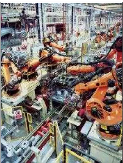
(a) Industrial Robots
Figure 2.1: Industrial robot in car production doing vehicle under body assembly (courtesy of
http://people.msoe.edu/~alhubaila/images/Industrial_Robotics_in_car_production.jpg)