DOI: 10.12928/TELKOMNIKA.v14i1.2742 129
Analysis of Handover Trigger Scheme Based on
Distance for LTE High-speed Railway Networks
Rui Zhang*, Muqing Wu, Yifan Zhang
Beijing University of Posts and Telecommunications, Beijing 100876, China *Corresponding author, e-mail: [email protected]
Abstract
In high-speed railway environment, frequent handovers and high handover failure probabilityresult in serious communication interruptions and call drops, which become pressing problem to be solved. Alternative reference point based handover scheme can be an applicative solution for high-speed rail. This paper analyzes the impact of handover location on the handover performance. And numerical analysis is utilized to give a method to determine the distance from the serving eNodeB and the adjacent one to the mobile terminal when handover is triggered. Handover failure probability is used as criteria for performance. Simulation results show that the proposed scheme has a better performance than typical event based scheme in high speed environment.
Keywords: handover trigger, high-speed rail, handover failure probability
Copyright © 2016 Universitas Ahmad Dahlan. All rights reserved.
1. Introduction
High-speed railways play an increasingly important part in people’s lives recent years [1]. The current broadband wireless communication systems optimized for low mobility environments cannot maintain adequate performance for passengers traveling on the high speed trains (HST) any longer. Typical hard handover supported by LTE systems reduces the complexity of the system architecture but simultaneously brings about higher handover failure ratio and the decline of the user experience in high-speed mobility environment [2].
Handover becomes a great challenge in the systems designed for high-speed rail mainly due to the following reasons: when the running speed of HST achieves 350km/h or even higher in the future, the time interval of every two handovers can be as short as 15s, given a size of about 1.5km which is typical in Macro cell [3], and it results in a high handover frequency; classical event handover algorithm triggers a handover procedure basing on HO hysteresis and Time to Trigger, which increases the time latency of handover and meanwhile it may lead to Radio Link Failure (RLF) before the user terminals successfully access to the target eNodeB. Several papers have provided optimized schemes for LTE handover. In reference [4], the authors analyzed the impact of propagation environment and velocity of UE on the handover performance. The reference [5] gave a threshold handover triggering scheme for wireless networks. Reference [6, 7] also introduced algorithms for LTE systems to improve handover performance.
In order to solve the problems mentioned above, the reference [8] proposed a handover algorithm using the particularity of the railway environment. According to reference [9], handover procedure could be executed based on GPS (Global Position System) information. But the handover reference point which is the most appropriate to achieve satisfying performance was not given. So in this paper, the analysis of handover trigger location will be proposed. Considering the path loss, log-normal shadowing and frequency selective fast fading, the handover performance based on handover failure probability at certain distance from the serving station can be figured out. In this way, the handover reference point can be determined through numerical analysis.
2. System Model and Location-based Handover Procedure Introduction
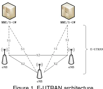
LTE network architecture is constituted of three parts as shown in Figure 1: evolved-NodeB (eevolved-NodeB), Mobile Management Entity (MME), and Serving Gateway (S-GW) / Packet Data Network Gateway (P-GW). The eNodeB performs all radio interface related functions such as packet scheduling and handover mechanism. MME manages mobility, user equipment (UE) identity and security parameters. S-GW and P-GW are two nodes that terminate the interface towards E-UTRAN and Packet Data Network respectively [10].
Figure 1. E-UTRAN architecture
Combined with the ground-to-train part, the network can be shown as Figure 2: the radio frequency signals generated at Base Band Unit (BBU) are firstly converted into optical signals and transmitted through the fiber to its Radio Remote Unit (RRU). BBU sends same signals to its RRUs and only part of the RRUs receive signals from the train at a certain time interval. For the network on the train, vehicle terminal provides the last hop communication for the subscribers in the carriage. In this paper, we consider the handover between source cell and target cell.
Figure 2. eNodeB development along railway
The followings show the steps of the location-based handover procedure steps:
From then on, source eNodeB begins to forward downlink data to the target eNodeB. Simultaneously, UE detaches from source eNodeB and synchronizes to the target one. And then, UE sends HO confirmation to target eNodeB about the success of radio handover.
Finally, target eNodeB begins to send its buffered data received from the source one and sends HO complete message to initiate data path switching. After MME/S-GW confirms the path switching, target eNodeB will notice source eNodeB to flush its forward downlink data buffer and release resource.
3. Numerical Analysis and Handover Reference Point Choice
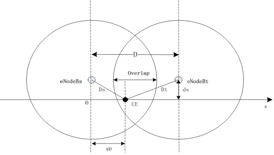
In this section, the numerical analysis of handover reference point choice is proposed, considering the handover failure probability. For the numerical evaluation, the analysis diagrammatic sketch is shown in Figure 3.
Figure 3. Analysis diagrammatic sketch
The distance between the serving eNodeB and the adjacent eNodeB isD. The distance between the eNodeB and railway isds. Dh represents the length of overlap region. The train location xis the distance between the vehicle station and origin in X-axis. Therefore, the distance between the vehicle station and the source and target eNodeBs can be expressed as
2 2
s s
D x d , ( )2 2
t s
D Dx d respectively. OFDM (Orthogonal Frequency Division Multiplexing) is utilized for data transmission. Thus, the baseband signal received from the source eNodeB can be obtained as follow:
1
sh is the log-normally distributed shadowing fading, h ts( ) is the small scale Rayleigh fading, N is the total number of subcarriers, dn is transmitted data and transmit power 2
[| | ]
d n
P E d , f is subcarrier spacing and s( )t indicates the zero mean Gaussian noise.
According to [11], the signal strength received from source eNodeB defined as Rsin dB can be calculated as follow:
Where 1 2 1
represents the shadow fading deviation, f TD sis
the normalized maximum Doppler frequency shift. ˆ ˆ( )
n n k
is the useful factor contributed to the th
n subcarrier, and can be expressed as:
1
The signal strength from target eNodeB can be defined similarly as Rtbased on Equation (2). When the train is in the overlap region, if the vehicle terminal is not triggered to handover before the signal strength from source eNodeB decays to a level lower than a threshold Twhich is the minimum received signal strength to maintain the communication, or the signal strength from target eNodeB is lower than Tafter the handover is triggered, the handover failure occurs. So the handover failure probability can be divided into failure before triggering and failure after triggering, denoted by Pf_band Pf_arespectively. Therefore, the point that has both minimized Pf_band Pf_acan be selected as the handover reference point.
In traditional GPS-based handover algorithm, the handover reference point is a statistical result based on repeated measurement. We suppose that the hysteresis level is U (dB). So the handover failure probability before triggering when the handover trigger point is x can be expressed as:
the handover failure probability after triggering can be expressed similarly as:
2
_ _
(1
) * (1
)
f f b f a
P
P
P
(6)4. Results and Analysis
The performance of the proposed scheme based on distance can be validated by simulation. The speed range of the train is supposed to be 60km/h to 360km/h. The overlap area of adjacent cells is assumed to be 1.5km.
The simulation parameters are shown in Table 1. The propagation model of Cost231-Hata is used [12], and it can be expressed as Equation (7):
46.3 33.9 lg c 13.82 lg b ( ) (44.9 6.55 lg b) lg m
L f H Hm H dC (7)
The channel model of this scene is mountain environment. The estimated
C
mcan be obtained from project experience as Equation (8):10.03
m
C
(8)Table 1. Simulation Parameters
List Energy Power
1 Bandwidth of Subcarrier 15kHz
2 Carrier Frequency 2.6GHz
3 System Bandwidth 10MHz
4 Transmission Time Interval(TTI) 1ms
5 Overlap 300m
6 Distance between eNodeB and Railway Line 100m
7 Transmitting Power 46dBm
8 Noise -148.95dB/sub-channel
9 Path Loss Refer to Eq. (7)
10
Log-normal Shadow Fading Standard Deviation=8dB Mean=0 11 Signal Threshold T -58dBm
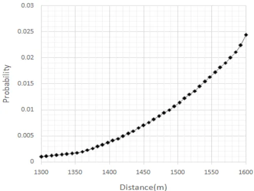
We choose the triggering points within 1300m~1600m region in the overlap area. The relationship between the handover failure and the triggering point is simulated. Figure 4 shows the analysis of handover failure probability before triggering happening.
And Figure 5 shows the tendency variation of handover failure probability after triggering happening at given locations. It can be seen that when triggering happens closer to the source eNodeB, a lower failure probability before triggering can be obtained, and it constantly gets higher evidently along with the location moving closer to the target eNodeB. Meanwhile, the failure probability after triggering has a downtrend presenting a contrary variation.
The handover failure probability when triggering within 1300m~1600m is shown in Figure 6. Comprehensively considering the failure probability before and after triggering happening, it can be seen that it goes up after dropping. This illustrates that when specific scenario is given, a small region suited to trigger handover in the overlap area can be analyzed according to the channel environment, so as to reduce the handover failure probability to acceptable range.
Figure 5. Handover failure probability after triggering
Figure 6. Handover failure probability when triggering at given location
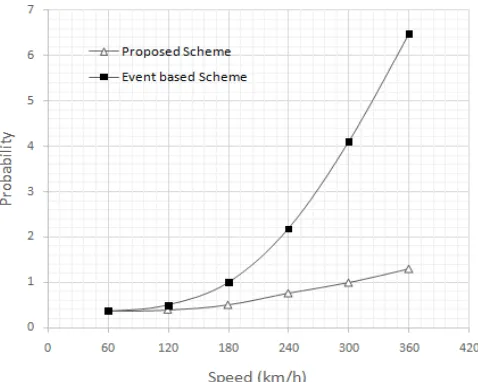
Figure 7. Performance comparison of traditional and proposed scheme
5. Conclusion
This paper has analyzed a handover scheme based on distance information for LTE high-speed rail networks. A method of selecting handover reference point is provided for scenarios given channel environment. Simulation results show that a small region suited to trigger in the overlap area can be obtained, and the handover performance can be increased by reducing the handover failure probability.The proposed scheme can adapt to the high-speed rail environment better than typical event based scheme, because it can eliminate ping-pong HO and achieve preferable handover failure probability.
Acknowledgements
This work was supported by Technology Major Projects (No.2011ZX03001-007-03).
References
[1] Chengwei L, Mingchin C, Mengchang C. Seamless Handover for High-Speed Trains Using Femtocell-Based Multiple Egress Network Interfaces. IEEE Transactions on Wireless Communications. 2014; 13(12): 6619-6627.
[2] Meng-Shiuan P, Tzu-Ming L, Men-Tsuen C. An Enhanced Handover Scheme for Mobile Relays in LTE-A High Speed Rail Networks. IEEE Transactions on Vehicular Technology. 2015; 64(2): 743-756.
[3] ETSI TR 102.281: Detailed requirements for GSM operation on Railways, v2.0.0. 2006.
[4] Saif-Ur-Rehman Q, Syed Junaid N, Mohammad P. The impact of propagation environment and velocity on the handover performance of LTE systems. Proc. of International Conference on Wireless Communications and Signal Processing. Su Zhou. 2010: 1-5.
[5] Liming C, Qing G, Zhengyu N, Kaiyuan J. A Threshold Based Handover Triggering Scheme in Heterogeneous Wireless Networks. Telkomnika (Telecommunication Computing Electronics and Control). 2014; 12(1): 163-172.
[6] Danish A, Rolf S. Improvement of LTE Handover Performance through Interference Coordination. Proc. of Vehicular Technology Conference (VTC). 2009: 1-5.
[7] Li J, Tian L, Zhou Y. An adaptive handover trigger scheme for wireless communications on high speed rail. IEEE International Conference onCommunications (ICC). 2012: 5185-5189.
[8] Linlin L, Muqing W, Yifan Z. A Handover Algorithm for LTE System based on the Target Cell Pre-Bearer in High-speed Railway Environment. International Journal of Advancements in Computing Technology. 2012; 4(22): 631-640.
[9] Linlin L, Muqing W, Wei W. A GPS-based handover algorithm in LTE high-speed railway networks.
Advances in Information Sciences and Service Sciences. 2012; 4(9): 205-213.
[10] 3GPP TS 36.423: Evolved Universal Terrestrial Radio Access Network (E-UTRAN) X2 Application Protocol (X2AP), V8.3.0. 2008.
[11] Tian L, Li J, Huang Y. Seamless Dual-Link Handover Scheme inBroadband Wireless Communication Systems forHigh-Speed Rail. IEEE Journal on Selected Areas inCommunications. 2012; 30(4): 708-717.