International Journal of Science and Research (IJSR)
ISSN (Online): 2319-7064Impact Factor (2012): 3.358
Volume 3 Issue 5, May 2014
ROV Trainer Kit for Education Purposes
Mohd Shahrieel Mohd Aras
1, Fadilah Abdul Azis
21, 2Department of Mechatronics, Faculty of Electrical Engineering, Universiti Teknikal Malaysia Melaka
Hang Tuah Jaya, 76100 Durian Tunggal, Melaka Malaysia
Abstract: This paper presents the Underwater Remotely Operated Vehicle (ROV) trainer or called it as the ROV Trainer for the educational purpose. Many underwater industries are involved in developing underwater robot in order to reduce human works as well as increase productivity, efficiency and monitoring. Therefore, the ROV was designed in order to replace the divers and reduce a risk to a diver itself. However, the major constraints to the ROV designed are understanding and knowledge the fundamental of the ROV design. Therefore, ROV Trainer is designed in order to give a basic knowledge and as a platform to test the control system of the ROV. ROV Trainer was a design based on maneuverability and performance of each component with minimum cost where the size of ROV can be varied based on user needed. The Peripheral Interface Controller (PIC) is used to control the movement of this ROV either as manual control or autonomous control. The experiment carried out from this ROV trainer such as buoyancy test, pressure test, measure thrust and controlling the ROV will be covered in ROV Trainer. This project will give many benefits for educational researcher, school educational kits and also related underwater industries by looking at ROV’s features with the needed minimum cost of implementation.
Keywords: ROV Trainer, buoyancy test, thrust measurement, pressure test, control strategy’s.
1.
Introduction
In 2011, the National Oceanography Directorate (NOD) under Ministry of Science, Technology and Innovation (MOSTI) introduces the first competition for an underwater competition for primary school in Putrajaya Maritime Centre that called Underwater Remotely Operate Vehicle (UROVeC). NOD was established on November 2000 serves as the National Focal Point for the coordination of research, development and commercialization and all related activities of oceanography and marine science in Malaysia. In 2012 and 2013, these underwater competitions were introduced for ordinary secondary school and secondary school for majoring in technical, respectively. In 2013 this competition was held in World Ocean Week 2013 (WOW 13) All the manual to design a simple ROV with Four Degree of Freedom (4 DOF) provided by the technical committee from MOSTI. This competition was supported by many industries involves on underwater fields such as Royal Institute of Naval Architects (RINA), Institute of Marine Engineering, Science and Technology (IMarEST) and MTC Engineering. In 2013, Underwater Technology Research Group (UTeRG) one of the research group in RIA from Faculty of Electrical Engineering, Universiti Teknikal Malaysia Melaka (UTeM) is invited to be one of the committee members as technical committee and the jury for that competition held in June 2013.
After technical briefing before this competition held in Faculty of Electrical Engineering, UTeM. The major problem faced by all students came to this technical briefing, including their teachers is the fundamental of the ROV is weak and no ideas how to design the ROV. Based on a simple manual given to the student and from YouTube does not enough to gives understand how to design the ROV. How to make faster the ROV for this competition? This is challenged to this student to be covered. Most of them just used a standard design of ROV based on manual given. The thruster that is a motor and propeller is same for all participants. That means the speed of thruster and the amount of thrust will be same. But, the difference is the design of the ROV. The size of the ROV is one of most of the participants
understanding the effect of size. Based on a small scale thruster, the size of the ROV should be not too big and heavy. Nobody wondered the rest of a factor to make the ROV faster, even their teacher also leaks of this knowledge. This reasons, the ROV trainer kit designed to give a clear overview and basic knowledge to students or young researchers.
2.
ROV Trainer Kit
The product specialty is to modeling of Remotely Operated vehicle (ROV) with different size using Right Side of General equation of an Unmanned Underwater Vehicle. Application of ROV Trainer kit is an educational purpose for underwater application and can control by remote control or Autonomous Control, complete with Driver and Interfaces between ROV Trainer and Personal Computer
2.1 Product Application
All ROV Trainer Kit features for educational purposes and be an important tool for Modeling of Remotely Operated Vehicle based on thruster configuration.
2.2Commercialization Potential
Educational and research activities for Secondary School, Poly-technique, University, private company, etc.
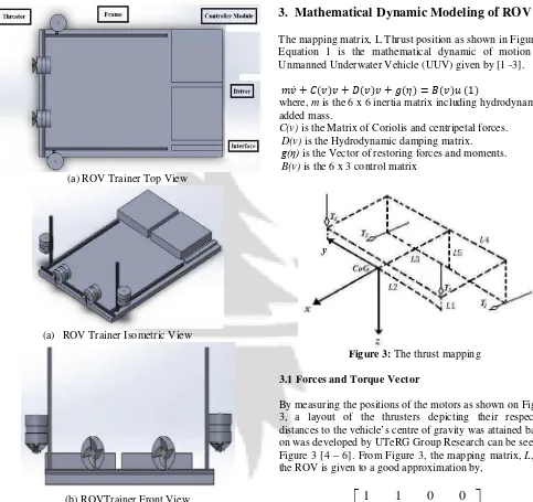
2.3 Solidwork Design
International Journal of Science and Research (IJSR)
ISSN (Online): 2319-7064Impact Factor (2012): 3.358
Volume 3 Issue 5, May 2014
(a) ROV Trainer Top View(a) ROV Trainer Isometric View
(b) ROVTrainer Front View
Figure 1: ROV Trainer Kit using Solidworks
2.4 List of Experiment
The ROV Trainer Kit come out with a standard experiment kit with 10 experiments. This experiment also can be diverge to a part of the experiment. In this paper, also including a few examples of experiments will be conducted.
Figure 2: List of Experiment
3.
Mathematical Dynamic Modeling of ROV
The mapping matrix, L Thrust position as shown in Figure 3. Equation 1 is the mathematical dynamic of motion for Unmanned Underwater Vehicle (UUV) given by [1 -3].
��� � ����� � ����� � ���� � ����� �1�
where, m is the 6 x 6 inertia matrix including hydrodynamic added mass.
C(v) is the Matrix of Coriolis and centripetal forces. D(v) is the Hydrodynamic damping matrix.
g(η) is the Vector of restoring forces and moments. B(v) is the 6 x 3 control matrix
Figure 3: The thrust mapping
3.1 Forces and Torque Vector
By measuring the positions of the motors as shown on Figure 3, a layout of the thrusters depicting their respective distances to the vehicle’s centre of gravity was attained based on was developed by UTeRG Group Research can be seen in Figure 3 [4 – 6]. From Figure 3, the mapping matrix, L, for the ROV is given to a good approximation by,
−
−
−
−
−
=
5
5
2
2
4
4
1
1
3
3
0
0
1
1
0
0
0
0
0
0
0
0
1
1
L
L
L
L
L
L
L
L
L
L
L
(2)While the thrust vector is given by,
=
4 3 2 1
T
T
T
T
U
(3)International Journal of Science and Research (IJSR)
ISSN (Online): 2319-7064Impact Factor (2012): 3.358
Volume 3 Issue 5, May 2014
matrix denote the distances from the centre of gravity to thethrusters. These values are either positive or negative corresponding to anticlockwise or clockwise moments respectively. The moments produced are responsible for affecting the vehicle’s attitude. As can be seen in the fifth row of the mapping matrix, the two vertical motors do not only contribute to pitch, but also to the two horizontal motors [7-8]. This implies that, when the vehicle is surging either forwards or backwards, the horizontal motors will affect the pitch of the vehicle. However, when performing underwater manoeuvres, this effect was not observed. This implies that the contribution to pitch by the horizontal motors is not significant. This is most likely attributable to the passive pitch control system. Each vertical motor observed in the fifth row is in fact an equidistant from the centre of gravity [9]. Consequently, applying equal forces to these motors when diving, surfacing or hovering will maintain the vehicle in a reasonably horizontal posture.
4.
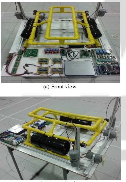
Results
Figure 4 (a) shows the actual ROV Trainer Kit. Two sample of ROV also including in this Trainer Kits for shows different set of thruster mapping as shown in Figure 4 (b) and (c). The example of experiment can be dobe by this ROV kits as depicted in Appendix. This ROV Kits comes with manual for experiment as described where at least 10 experiments can be done as shown in Figure 5.
(a) Front view
(b) Isometric view
(c) Side view with different ROV configuration
Figure 4: ROV Trainer Kits with different view
Figure 5: The front page for manual of ROV Trainer.
5.
Conclusion
The Underwater Remotely Operated Vehicle (ROV) trainer or called it as the ROV Trainer for educational purpose are successful design. This ROV Trainer is designed in order to give a basic knowledge and as a platform to test the control system of the ROV. ROV Trainer was a design based on maneuverability and performance of each component with minimum cost where the size of ROV can be varied based on user needed. This project will give much benefit for educational researchers, school educational kits and also related underwater industries by looking at ROV’s features with the needed minimum cost of implementation.
6.
Acknowledgement
We wish to express our gratitude to honorable University, Universiti Teknikal Malaysia Melaka (UTeM) especially for Underwater Technology Research Group (UTeRG) and Faculty of Electrical Engineering for give the financial as well as moral support for complete this project successfully. Furthermore, we wish to express our appreciation to final year students Faizul Izwan Ibrahim and Lee Dai Cong, who contribute to the development of this ROV Trainer Kit.
References
Internationa
Technology: Theory and Applications pp 18-23, 2012.
[2]Aras, M.S.M, S.S. Abdullah, Rashid, M Ab, Aziz, M.A.A, Development underwater Remotely Operated Veh Identification for depth control, Journ and Applied Information Technology, 136-145, 2013.
[3]Mohd Aras, Mohd Shahrieel and Mohd and Abdul Azis, Fadilah and Fara Ashiki Analysis Movement of Unmanned U using the Inertial Measurement Un Journal of Emerging Science and Engi (10). pp. 47-53. ISSN 2319–6378 [4]Mohd Shahrieel Mohd Aras, Shahru
Azhan Ab Rahman, Muhammad Thruster Modelling for Underwate System Identification Method, Intern Advanced Robotic Systems, Vol. 10, 2013.
[5]Ali, Fara Ashikin and Abdul Azis, Aras, Mohd Shahrieel and Muhammad Shahrum Shah, Abdullah (2013) De Contactless Thruster of Unmanned U International Review of Mechan (I.RE.M.E.), 7 (7). pp. 1413-1420. ISSN [6]Ali, Fara Ashikin and Mohd Aras, M
Abdul Azis, Fadilah and Sulaima, M Ismail, Jaaffar (2013) Design and Deve Depth Control of Remotely Operated using Thruster System. In: Mala Universities International Conference Technology (MUCET), 3-4 Decembe Pahang.
[7]Louis Andrew Gonzalez, Design, Mode of an Autonomous Underwater Vehicl University of Western Australia, 2007. [8]T.I. Fossen, Guidance and control
Wiley, New York, 1994.
[9]Mohd Aras, Mohd Shahrieel and Jaa and Anuar , Mohamed Kassim ,Tuning Input Fuzzy Logic Controller Based Surface Approximation Method For Underwater Remotely Operated Veh Engineering and Applied Sciences, 8 ISSN 1816-949X, 2013.
Author Profile
Mohd Shahrieel b Mohd Aras is of Electrical Engineering, Malaysia Melaka UTeM. He currently in Control and Automation, F Engineering, Universiti Teknology Malaysia. His focusing on control system design of underw primary interests related to nonlinear underw Artificial Intelligence.
Fadilah Binti Abdul Azis
Mechatronics Department in Malaysia Melaka (UTeM). She Mechatronics Engineering (Hons Islamic University Malaysia (IIUM) Mechatronics Engineering from University Her research interest includes in the Emergin
ational Journal of Science and Research (IJSR)
ISSN (Online): 2319-7064Impact Factor (2012): 3.358
Volume 3 Issue 5, May 2014
ations 2012 (USYS'12),M.Z.A, Rahman, A. and Modeling of Vehicle using System Journal of Theoretical gy, Vol. 56 No 1, pp
ohd Farriz , Md Basar Ashikin , Ali (2013) Underwater Vehicle Unit. International Engineering (IJESE), 1
rum Shah Abdullah, Azhar Abd Aziz, ater Vehicle Using ternational Journal of
No 252, pp 1 – 12,
Fadilah and Mohd mmad Nur , Othman and
Design A Magnetic Underwater Vehicle.
chanical Engineering SSN 1970-8734.
Mohd Shahrieel and Mohamad Fani and evelopment of Auto ated Vehicle (ROV) Malaysian Technical nce on Engineering &
ber 2013, Kuantan,
Modelling and Control ehicle, Master Thesis, 007.
of ocean vehicles,
Jaafar, Hazriq Izzuan uning Process Of Single On Linear Control Depth Control Of Vehicle. Journal of
8 (6). pp. 208-214.
is a lecturer at Faculty Universiti Teknikal currently pursues his PhD
Faculty of Electrical His current research is erwater technology. His derwater robotics and
is a lecturer of Universiti Teknikal She has a Bachelor of (Hons) from International (IIUM) and a MSc in of Siegen, Germany. erging Technology focus
areas such as Underwater Techn Structures. She is currently wor underwater vehicle for underwater
Appendix
Example of Experiment 1 and Experiment 1: Buoyancy Test Objectives:
To understand the concepts of To measure the buoyancy force Theoretical:
Buoyancy is the tendency of either to be floated or sink. If the weight of water displaced, and vice versa [6]. If the disp object it has equal tendency buoyancy has been classified buoyancy, neutral buoyancy shown in Figure 1.
Figure 1: Classificatio
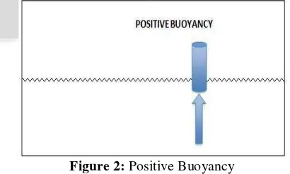
Positive Buoyancy -The condit buoyancy force relationship of floating on the surface of the fl
Figure 2: Posi
Neutral Buoyancy - The condition
weight and the buoyancy force
(IJSR)
Technology and Smart Material working on the development of ater.
and 2 est
buoyancy force. force.
of objects immersed in water the object weight is more than d, it will more tend to submerge isplaced water is the same, the to float as it does sink. The ied into three which is positive ncy and negative buoyancy as
ation of Buoyancy State
onditions where the weight and the of the object which tend to be fluid.
ositive Buoyancy
Internationa
sink nor rise in a fluid. The neutral buoy the object weight is equal to the fluid it disp
Figure 3: Neutral buoyanc
Negative Buoyancy - The condition wh
greater than the buoyancy force of the o objects will be more tend to submerge to fluid. The object has negative buoyancy fluid and there is no air inside the tank.
Figure 4: Negative Buoya
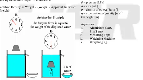
Formulation (Archimedes Principle) Archimedes Principle: “When a solid bod completely immersed in water, the appar will be equal to the weight of the displac buoyancy concept is calculated when the is different than the force pushing down fluid. Formula for Density of immersed obj density of the fluid object is immersed in:
Relative Density = Weight / (Weight - A Weight)
ational Journal of Science and Research (IJSR)
ISSN (Online): 2319-7064Impact Factor (2012): 3.358
Volume 3 Issue 5, May 2014
uoyancy occurs whendisplaced.
ancy
where the weight is object in which the to the bottom of the ncy to immerse in the
yancy
body is partially or pparent loss in weight laced liquid” [7].The force is pushing up to the object in the object relative to the n:
Apparent Immersed
Figure 5: Archi
The buoyant force is the differ and the buoyant force (F2).
��� ��� F� (1.1)
��� �� (1.2)
� � ���� (1.3)
��� ����� (1.4)
� � ���� (1.5)
��� ����� (1.6)
��� ����� � ����� (1.7) (
��� ����� � ����� � ���
Where,
� � ��� �� (1.9)
��� ���� (1.10)
Where,
� � �� (1.11) (1.11)
��� ��� (1.12)
��� �� � ���∆� (1.13)
Apply the density equation:
� � �� (1.14)
So the general equation for buoy
��� ��� (1.15)
Where,
P = pressure [kPa] A = area [m3]
� = density of object [kg m-3]
� = acceleration of gravity [m h = height [m]
Apparatus:
i. Aluminium plate, ii. Small tank iii. Measuring Tape iv. Weighting Machine.
v. Weigthing 5g
(IJSR)
chimedes Principle
fference between the weight (F1)
( (1.7)
������� ��� (1.8)
buoyant force:
International Journal of Science and Research (IJSR)
ISSN (Online): 2319-7064Impact Factor (2012): 3.358
Volume 3 Issue 5, May 2014
Procedure:1) Measure the weight of aluminum plate and determine the density of aluminium on Table 1 in appendix.
2) Measure the size of aluminuim plate. And use the formula given to calculate the size of float so that the aluminium will be slightly positive buoyancy between (90 to 95 %)
3) Tape the determined float by calculation to aluminuim plate and testing into small tank.
4) Put the wieght into the aluminum plate (Increased the weight of weithing plate 5g and observed the aluminuim plate position) until the aluminium plate will be neutral buoyancy.
5) Observed and recorded the data.
.Appendix- Table 1: Density Table
The density of surface seawater ranges from about 1,020 to 1,029 kgm−3, depending on the temperature and salinity. Deep in the ocean, under high pressure, seawater can reach a density of 1,050 kgm−3 or higher. Seawater pH is limited to the range 7.5 to 8.4. The speed of sound in seawater is about 1,500 metres/second, and varies with water temperature, salinity, and pressure.
Experiment 2: Thrust Measurement
Objectives:
• To measure thrust for different types of propeller.
• To study the effect of propeller design to thrust.
Theory:
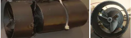
A thrusters is an electromechanical device equipped with a motor and propeller that generates thrust to push an Underwater Vehicle as shown in Figure 1. Thrusters are generally propellers driven by electrical DC motors [4]. Therefore, thrust force is simultaneously affected by motor model, propeller design, and hydrodynamic effects. For this experiment focused more on propeller design.
Figure 1: Completed thrusters -propeller with 3 blades
The propeller is the actuator that converts the motor power into thrust, in order to move the submarine through the surrounding media as shown in Figure 1. This Propeller can divide into two categories such as forward and reverse propeller. For forward propeller the thrust to forward, right and floating direction while for reverse propeller the thrust to reverse, left and submerge direction.
Equation 1 is to measure a power that comes out from thrusters (Thrust is a reaction force described quantitatively by Newtonn’s, second order and third laws. When a system expels or accelerates mass in one direction the accelerated mass will cause a proportional but opposite force on that system as shown in Figure 2) and speed of propeller.
Power (Watts) = thrust (Newton) x speed (ms-1) (1)
Propellers are manufactured having from 2 up to 8 blades. The fewer the number of blades, the higher the propeller efficiency. However, the total thrust is divided on the blades which means that ships with large power requirements and heavy loaded propeller need more blades. Fewer blades also introduce more vibration and therefore submarines used in warfare usually have up to 8 blades. Three blades propeller are the most common for normal operating small ROV
Apparatus: i. Thruster ii. Thrust Testing
iii. Propeller (4 types of propeller)
Procedure:
1) Prepared the thruster and make sure the condition is ready for launch as shown in Figure 2.
International Journal of Science and Research (IJSR)
ISSN (Online): 2319-7064Impact Factor (2012): 3.358
Volume 3 Issue 5, May 2014
2) Make sure the thrust testing should be set to zero beforestart the thruster on.
3) Turn on the thruster with right direction (vertical motion) and recorded the thrust obtained and repeat 5 times. 4) Change the type of propeller and repeat again 1 -3. Also
consider change of type of motor. 5) Recorded all data in Table.
No Type of Propeller Thrust on surface (N)
Thrust on underwater (N) 1 3Blades propeller plastic
2 3 Blades propeller
alumimuin
3 4 Blades propeller plastic