Speed Control Analysis of Brushless DC Motor Based on
Maximum Amplitude DC Current Feedback
M.A.A.Hassan 1,a, A.R.Abdullah 1 and N.Bahari 1
1Universiti Teknikal Malaysia Melaka, Hang Tuah Jaya, 76100 Durian Tunggal, Melaka, Malaysia
Abstract. This paper describes an approach to develop accurate and simple current
controlled modulation technique for brushless DC (BLDC) motor drive. The approach is applied to control phase current based on generation of quasi-square wave current by using only one current controller for the three phases. Unlike the vector control method which is complicated to be implemented, this simple current modulation technique presents advantages such as phase currents are kept in balance and the current is controlled through only one dc signal which represent maximum amplitude value of trapezoidal current (Imax). This technique is performed with Proportional Integral (PI) control algorithm and triangular carrier comparison method to generate Pulse Width Modulation (PWM) signal. In addition, the PI speed controller is incorporated with the current controller to perform desirable speed operation of non-overshoot response. The performance and functionality of the BLDC motor driver are verified via simulation by using MATLAB/SIMULINK.The simulation results show the developed control system performs desirable speed operation of non-overshoot and good current waveforms.
1 Introduction
Several years ago, many types of motors were developed to minimize the problems that are faced by brushes DC motors. Among those types of motors, the use of brushless DC (BLDC) motor has recently received much attention. This is because the BLDC motor offers many advantages including higher efficiency, low maintenance, and more compact construction.
In many electrical drive applications, it is desirable to achieve dynamic speed response and low current ripple during operation. The dynamic speed response measures how effectives the system responses to a change in input signal. In the motor operation, the motor current and torque relate to each other. Therefore, the torque ripple can be directly controlled by regulating the armature current ripple. Several papers were reported to achieve this requirement, for examples [1] fully utilized the available DC link voltage through over modulation strategy and [2] generated the maximum possible voltage vector that is tangential to the flux component to have lower current ripple. Ultimately, all these methods used a vector control which is complicated to be implemented. Therefore, a simple current modulation method incorporating with speed control loop is developed to perform desirable speed operation of non-overshoot and produces low current ripple.
This current modulation is introduced as a method to generate Pulse Width Modulation (PWM) which completely characterizes current ripple based on maximum amplitude of phase current ( )
a M. A. A. Hassan: [email protected] DOI: 10.1051/
C
Owned by the authors, published by EDP Sciences, 2014
/201
conf 41303 00
matec 7
This is an Open Access article distributed under the terms of the Creative Commons Attribution License 2.0, which permits unrestricted use, distribution, and reproduction in any medium, provided the original work is properly cited.
[3]. is a single dc signal which brings information of maximum amplitude current. This signal is obtained from rectification process of the three phases armature currents. Base on this strategy, the advantages are identified as a the phase currents are kept in balance and the current is controlled through only one dc signal which represents . These advantages and characteristic allows the triangular carrier to be assigned as current control strategy because it is simpler and accurate [4]. In speed loop, Proportional Integral (PI) algorithm controller is executed to correct the speed error through PI gain multiplication and integration process and produce current reference for current controller. Thus, incorporation triangular carrier current control with speed control allows the BLDC motor to perform at desirable speed operation with low current ripple.
2 Control system
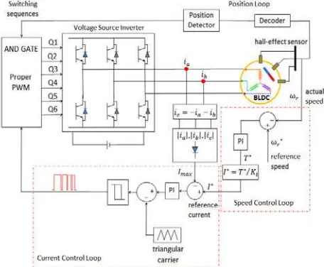
This paper presents a simple current controlled modulation technique for BLDC motor control system. The control system is developed based on speed control loop, current control loop and position loop. Figure 1 presents a schematic of the control strategy.
Based on this control system, actual motor speed ( ) is compared with reference speed ( ), and the produced speed error is processed in PI speed controller. The output of the controller is in reference torque value ( ). Therefore, the torque reference is converted to equivalent reference current ( ) by divide with motor torque constant ( ). This current becomes input of current controller and being compared with maximum amplitude of single DC current ( ). The maximum amplitude DC current is obtained from three phases quasi-square armature currents. The current phase A ( ) and phase B ( ) are sensed by current sensor meanwhile the current phase C ( ) is estimated from both current information of phase A and B. Then, the three phases current are rectified to produce maximum amplitude of single DC current. From the comparison between and , the current error signal is obtained. This error is passed through PI current controller and being processed. The output of the controller is compared with a fixed amplitude and frequency triangular waveform to produce PWM signal. This PWM signal and switching sequences from position loop are then processed to generate modulation signal for each transistor of voltage source inverter. Performance of torque is directly commanded by and is assigned by speed error that has been fixed. The speed error and current error is restricted by controller and triangular carrier to perform desirable speed operation of non-overshoot and good real-time performance with low current ripple. The strategy becomes simple because the control only needs command from single dc current instead of three quasi-square current template [4].
3 Current control design
The concept of current controlled modulation method is based on comparison of phase current with reference current and the error between them is used to drive the inverter. During the operation, the main task of this control method is to force the phase current to follow the reference current.
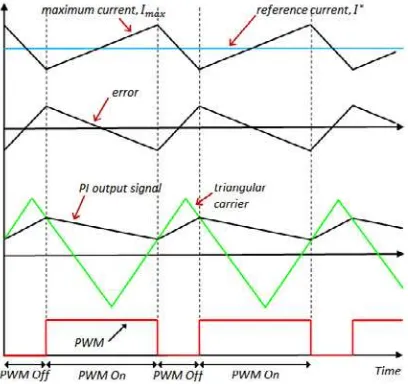
For triangular carrier control, the switching frequency is constant. Figure 2 represents the concept of triangular carrier control. In this method, the maximum amplitude phase current is compared to the reference current and the error of the current becomes input for PI current controller which produce altered signal to restrict the error and improve the performance of inverter. Then, the altered error signal is compared to fixed amplitude and frequency of triangular carrier. If this error is positive and larger than triangular carrier the switch is turned ON and if the error is positive and smaller than triangular carrier the switch is turned off [7].
Figure 2.Ideal waveform of maximum current, error signal and control signal.
The PI current controller is used in this method to suppress the harmonics, noise, current ripple and total harmonic distortion. The values of Kp and Ki determine transient response and steady state error of the triangular carrier control. The value of both gains can be obtained from the equation below [8].
(1)
(2)
Where, = proportional gain, = integral gain, = phase inductance, = triangular carrier frequency, = DC supply voltage.
The output of PI current controller in discrete domain can be expressed as
(3)
4 Speed control design
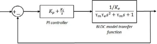
The current modulation methods that being simulated are triangular carrier control. This method is designed to incorporate with speed control loop to improve the dynamic response and reduce the steady-state error of speed response. Comparison between reference speed and motor speed produce error and being processed in PI speed controller. The general form of PI controller arrangement with BLDC model system arrangement is displayed in Figure 3 for tuning procedure. The equation model for BLDC motor is derived from [9]. Output of PI controller is in torque value. Thus, reference current ( ) is obtained by divide torque value with motor torque constant ( ).
Figure 3. PI schematic for PI controller with BLDC system model arrangement.
5 Simulation result
Simulation model is established using MATLAB/SIMULINK to evaluate the performance of the system. The main parameters of BLDC motor for simulation are listed in Table 1. The system is simulated at sampling time 2μsec, and for current control parameter, the triangular carrier frequency is 15 kHz.
Table 1. Simulation parameter of BLDC motor.
Parameter Value
Phase resistance 0.804 [Ω]
Phase inductance 0.000439 [H]
DC link voltage 24 [V]
Number of pole 4
Torque constant 0.04 [Nm/A]
Voltage constant 4.168 [V/krpm]
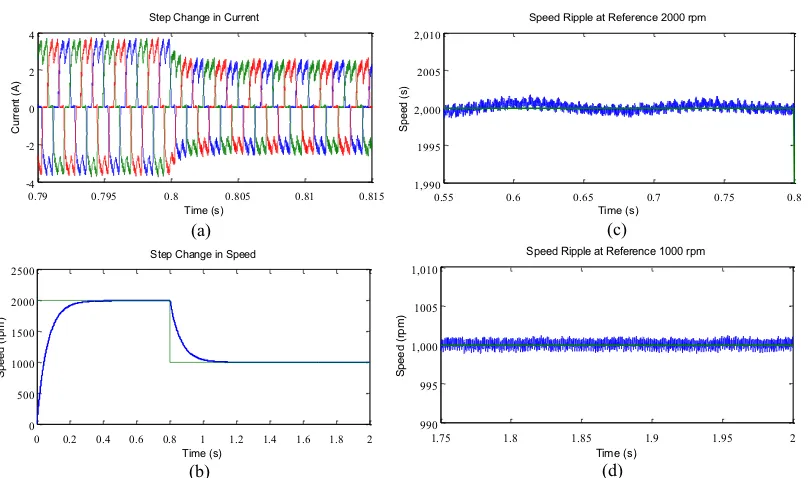
The current response, speed response and speed ripple at load operation condition are presented respectively in Figure 5 (a), (b), (c) and (d). The current shows it reduction from 3A to 2A respectively to the speed step change from 2000 rpm to 1000 rpm. It can be observed that the load operation cause the motor run with higher current supply compare to no load operation. For speed ripple, it show that the response at both level of speed is controlled and restricted within it references.
0.79 0.795 0.8 0.805 0.81 0.815 (a) Current response (b) Speed response (c) Speed ripple at 2000 rpm (d) Speed ripple at 1000 rpm.
0.79 0.795 0.8 0.805 0.81 0.815 (a) Current response (b) Speed response (c) Speed ripple at 2000 rpm (d) Speed ripple at 1000 rpm.
6 Conclusion
A different control strategy for brushless dc machines has been presented. It is based on the generation of quasi-square currents using only one current controller for the three phases and incorporating with speed control loop. The advantages of this strategy are listed as very simple control scheme, the phase currents are kept in balance and the current is controlled through only one dc signal. These characteristics allow for implementation of the triangular carrier as a current control strategy for the power transistors, which is simpler than other options and also offers .good performance in speed and current waveform. The simulation results show the agreement with theoretical where the developed control system performs desirable speed operation of non-overshoot and good current waveforms. Therefore, it is expected that this simple control system for BLDC motor drives will help reduce the complexity of motor control hardware.
References
[1] A. Jidin, N. Idris, A. Yatim and M. Elbuluk, “A Novel Overmodulation and Field Weakening Strategy for Direct Torque Control of Induction Machines” Industry Applications Society Annual Meeting, 2008. IAS '08. IEEE, (2008)
[2] A. Jidin, N. Idris, A. Yatim, T. Sutikno, and M. Elbuluk, “An Optimized Switching Strategy for Quick Dynamic Torque Control in DTC-Hysteresis-Based Induction Machines”, IEEE Transactions on Industrial Electronics, Vol. 58, pp. 3391-3400, (2011)
[3] G.R. Kumar, K. N. V. Prasad, and M.A.N. Doss, “Improve the Transient Response of Speed and Torque Ripple Minimization of the BLDC Motor by Varies Controllers”, Computer Communication and Informatics (ICCCI), International Conference on, 10-12 Jan 2012,Vol. 1, no.6, (2012)
[4] G.MadhusudhanaRao, and B.V.SankerRam, “Speed Control of BLDC Motor with Common Current”, International Journal of Recent Trends in Engineering, November, Vol 2, No. 6, pp 182-187,(2009)
[5] M.R. Feyzi, M. Ebadpour, S.A.K Mozaffari Niapour, and A. Feizi, “A New Single Current Strategy for High-Performance Brushless DC Motor Drives”, Electrical and Computer Engineering (CCECE), 24th Canadian Conference on, May, pp.424,(2011)
[6] H. S. Chuang, K. Yu-Lung, and Y.C. Chuang, “Analysis of Commutation Torque Ripple using Different PWM Modes in BLDC Motors”, Industrial & Commercial Power Systems Technical Conference - Conference Record 2009 IEEE, May, Vol. 1, no. 6, pp.3-7,(2009)
[7] H. M. Soliman, and S. M. E. L Hakim, “Improvement the Current Control Methods for Three Phase Voltage Source Inverter to Drive the Permanent Magnet Synchronous Motor”, International Journal of Engineering and Advanced Technology (IJEAT), October, ISSN: 2249 – 8958, Vol. 2, Issue-1,(2012)
[8] J. Dixon, S. Tepper, and L. Moran, “Practical Evaluation of Different Modulation Techniques for Current-Controlled Voltage Source Inverters,” Electric Power Applications, IEE Proceedings, Jul, vol.143, no.4, pp.301,306,(1996)