Abstract—This paper proposed a development of 5.8 GHz Artificial Magnetic Conductor, AMC using very thin substrate with thickness of 0.13 mm. Different shapes of PEC metallization are discussed in order to achieve the highest bandwidth of unit cell AMC. Another approaches for increasing the bandwidth is by applying the ring patch around the substrate as well as implementing the DGS ground plane. The proposed design produces 1.96 % bandwdith of unit cell. Applying the 2 x 4 unit cell arrangement gives the best result for directivity equal to 6.75 dBi, gain of 6.83 dB, efficiency = 98.41 % and return loss = -45.63 dB.
Index Terms—Artificial magnetic conductor, gain and Radio frequency identification.
I. INTRODUCTION
Metamaterial structure defined by Rodger M. Walser as cited in [1] as macroscopic composites having synthetic; three dimensional and periodic architecture designed to produce as optimized combination, not available in nature. The use of metamaterial structure such as electronic band gap, EBG or Frequency Selective Surface, FSS gives advantages in communication electronic component such as antenna, filter and microwave couplers. Considering the equation (1) and (2), as the thickness, h of the substrate decreased, the inductance, L will increased. Whilst, the value of resonant frequency will be decreased (the capacitance, C is kept maintained)
, 1
Another characteristic of AMC need to be measured is the bandwidth. Referring to (3), the bandwidth of the AMC can be increased by increasing the inductance or reducing the capacitance. In [2] stated that the capacitive element can be decreased by using a substrate with low permittivity or by increasing the gap between the metallization edge and unit
Manuscript received October 20, 2014; revised December 24, 2014. Maisarah Abu is with the Telecommunication Engineering Department
of Universiti Teknikal Malaysia Melaka, Malaysia (e-mail:
Eryana Eiyda Hussin is with the Communication Engineering
Department, UCSI University, Malaysia (e-mail:
Rose Farahiyan Munawar is with the Engineering Materials Department
of Universiti Teknikal Malaysia Melaka, Malaysia (e-mail:
Hidayah Rahmalan is with the Software Engineering Department of
Universiti Teknikal Malaysia Melaka, Malaysia (e-mail:
cell-edge. Hence, in this paper the development of 5.8 GHz AMC on 0.13 mm substrate with different metallization modification of the copper patch will be proposed.
performance of the antenna compared to the conventional ground plane. In [3] stacked ring-patch artificial substrate is designed with a combination of square patch (upper layer) and square ring patch (bottom layer) shows that the structure can act as high impedance surface at certain frequency with good surface wave suppressing of 0° phase angle. In RFID application, the use of AMC give advantage by improving the performance of the RFID tag by increasing the gain, directivity as well as the reading distance to the reader [4-8]. In addition, the use of AMC can solve the problem of metallic object detection in RFID tag application. The unique feature of AMC is it can reduce the effect of surface wave by removing the unwanted signal formed by the metal or copper substance. Thus, smoother radiation pattern with low backlobe power will be formed [9]-[11].
Paper [12] presented the dual-band hexagonal AMC for wearable antenna application designed on felt fabric of 4mm thickness produce the output bandwidth of 11.76 % and 18.18 % at 2.4 GHz and 5.8 GHz respectively. Later in [13], the novel design of broadband AMC (>20%) unit cell is presented with six-dipoles shape arrangement at each 60° into the hexagonal patch served to modified the resonant frequency of operation. The presented hexagonal AMC shows polarization-angle independency, low cross-polarization angle and ±10° angular margin stability when applied to different incidence of angle from 0° to 60°.
II. DESIGN PROCEDURES AND RESULTS DISCUSSION
This section will discuss the optimization steps and the simulated results of 5.8 GHz Artificial Magnetic Conductor including its parametric study, incidence of angle and the integration between dipole antenna and AMC.
A. AMC with Different Copper Metallization Shape Table I shows five different shape of polygons unit cell designed in the same substrate of fastFilm TM-27. The simulation results show different bandwidth percentage for each polygon unit cell shape. The octagon unit cell AMC (with 8-edges) shows the highest bandwidth percentage compared to others. It increase 57.14 % of bandwidth compared to the tetragon (4-edges) shape.
Design Synthesis of 5.8 GHz Octagonal AMC on a Very
Thin Substrate
Taking the consideration in Table I, the octagon shape will be used for further modification. The full patch octagon AMC is modified by introducing slots into the shape as in Fig. 1. Four slots with dimension of 0.7 mm×4.5 mm are inserted into the design had reduced the bandwidth until 1.01 %. However, when applying the square-outer-ring into the design is in Fig. 2 had increase the bandwidth to 1.40 %.
TABLEI:THE EFFECT OF DIFFERENT SHAPE UNIT CELL METALLIZATION TO THE BANDWIDTH
AMC Unit cell Shape Bandwidth
Tetragon 0.77 %
Hexagon 1.04 %
Octagon 1.21 %
Decagon 0.98 %
Dodecagon 0.97
B. Octagonal Shape Modification
Another method of increasing the bandiwdth is by applying the defected groud plane (DGS) at the back of the structure by replacing the conventinal full PEC ground plane [14]. There are two types of DGS to be implemented; DGS 1 (with same metallization shape) and DGS 2 (with opposite metallization shape). The disparity are shown in Fig. 3(a) and Fig. 3 (b).
Fig. 1. Octagonal AMC with four rectangular slots.
Fig. 2. Octgonal AMC with four rectangular slots and square-outer-ring.
(a) (b)
Fig. 3. (a) DGS with same metallization shape and (b) DGS with opposite metallization. (shaded areas are the metallization of PEC patch).
From the simulation results of octagonal AMC with four rectangular slots and DGS ground plane shows that the DGS with opposite metallization increase more bandwidth compared to the DGS with same metallization shape. Table II shows the comparison of bandwidth values for octagonal AMC with different metallization made to the original octagonal shape AMC. The final structure of Octagonal AMC with four rectangular slots, full ground plane, outer square ring and DGS 2 shows the simulated bandwidth of 1.96 %.
Frequency (GHz)
5.70 5.75 5.80 5.85 5.90
M
ag
n
it
u
d
e
(d
B)
-2.5 -2.0 -1.5 -1.0 -0.5 0.0
0° 10° 20° 30° 40° 50° 60°
(a)
Frequency (GHz)
5.0 5.5 6.0 6.5 7.0
Re
fle
ct
io
n
Ph
as
e
(°
)
-200 -100 0 100 200
0° 10° 20° 30° 40° 50° 60°
(b)
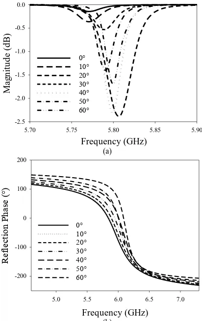
Fig. 4. (a) Magnitude and (b) phase of Square-Ring Octagonal AMC with DGS when applied to different incidence angle from 0° to 60°.
C. Incidence of Angle
By using the FSS Unit Cell Boundaries Template in CST Microwave Studio Software, the structure is now being simulated at different angle from 0° to 60°. Fig. 4 shows the simulated magnitude and phase of Octagonal AMC with four rectangular slots, outer square ring and DGS 2.
negative side). Meanwhile, the bandwidths are increased when applied to incidence angle from 0° to 40° but started decreasing as the incidence angle change to 50° and 60°.
TABLEII:THE COMPARISON OF BANDWIDTH VALUES FOR OCTAGONAL
AMC WITH DIFFERENT METALLIZATION MADE TO THE ORIGINAL
OCTAGONAL SHAPE AMC
AMC Bandwidth
Full plane octagonal AMC with full ground plane 1.04 % Octagonal AMC with four rectangular slots and full
ground plane 1.01 %
Octagonal AMC with four rectangular slots and full
ground plane and outer square ring 1.40 %
Octagonal AMC with four rectangular slots, outer
square ring and DGS 1 1.44 %
Octagonal AMC with four rectangular slots, outer
square ring and DGS 2 1.96 %
D. AMC-Dipole Integration
In this part, the Octagonal AMC with four rectangular slots, outer square ring and DGS 2 will applied to 5.8 GHz dipole antenna to measure the performance in term of gain,
5.8 GHz dipole antenna with 2 x 1 Octagon AMC 5.8 GHz dipole antenna with 2 x 2 Octagon AMC 5.8 GHz dipole antenna with 3 x 2 Octagon AMC 5.8 GHz dipole antenna with 2 x 4 Octagon AMC
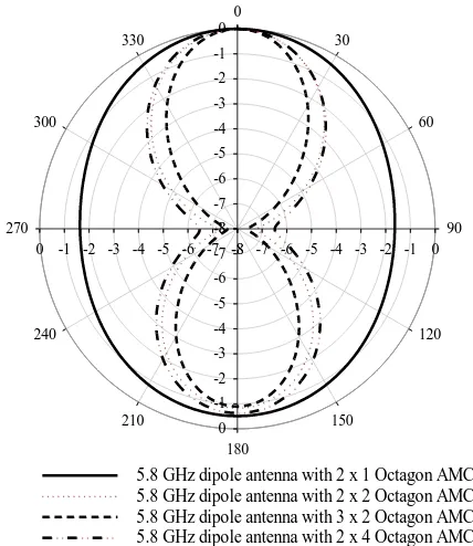
Fig. 5. Radiation pattern for Octagonal AMC with four rectangular slots, outer square ring and DGS 2 with various unit cell arrangements.
Fig. 5 shows the simulated S11 of Octagonal AMC with four rectangular slots, outer square ring and DGS 2 with different arrangement. The 2×4 unit cell arrangement shows the best value of magnitude at resonant. The smallest gain shows by the 2×1 unit cell arrangement which is the smallest size compared to other unit cell arrangement. For this structure, two types of unit cell arrangement can be suggested to be used in RFID tag application; 2×2 and 2×4 unit cell arrangament. Fig. 6 shows the 2×4 Octagonal AMC with four rectangular slots, outer square ring and DGS 2 applied to the dipole antenna with dimension of 26.2 mm×52.4 mm.
Fig. 6. Octagonal AMC with four rectangular slots, outer square ring and DGS 2.
52.4 mm
26.2 mm
From the radiation pattern shows in Fig. 7, the radiation occur at both front and back direction. Which means, the use of Octagonal AMC with four rectangular slots, outer square ring and DGS 2 still maintaining the properties of dipole antenna without reducing the backlobe radiation. The radiation pattern shows that the antenna still having the back-lobe radiation but in the same time improve the major-lobe radiation. For 2×1 Octagonal AMC with four rectangular slots, outer square ring and DGS 2 unit cell, the power pattern forms like a circle shape. It means that the radiation of the antenna can be received around the 360° angle. While the other three unit cell arrangement shows eight-shape radiation but with different value of angular width.
0
5.8 GHz dipole antenna with 2 x 1 Octagon AMC 5.8 GHz dipole antenna with 2 x 2 Octagon AMC 5.8 GHz dipole antenna with 3 x 2 Octagon AMC 5.8 GHz dipole antenna with 2 x 4 Octagon AMC
Fig. 7. Radiation pattern for Octagonal AMC with four rectangular slots, outer square ring and DGS 2 with various unit cell arrangements.
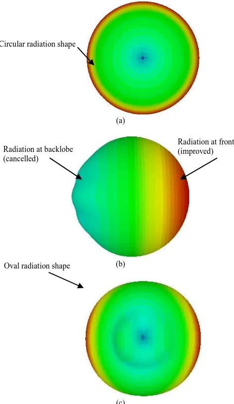
The final conclusion is the 2×4 arrangement gives the best results where the directivity = 6.75 dBi, gain = 6.83 dB, efficiency = 98.41 % and return loss = -45.63 dB. Fig. 8(a) shows the farfield view of dipole antenna (without attached to AMC). The maximum radiation can be seen to be at 360° around the structure. Then, the farfield view in Fig. 8(b) shows the maximum radiation for Octagonal AMC with four rectangular slots and full ground plane only occur on the front lobe. This is happens because the full PEC plane had reflect all the radiation from the backlobe. However, in Fig. 8(c) by applying the DGS 2, the backlobe radiation is increased as well as the frontlobe. The oval shape of farfield shows that the use of Octagonal AMC with four rectangular slots, outer square ring and DGS 2 with 2×4 unit cell arrangements had increase the radiation of the 5.8GHz dipole antenna.
III. CONCLUSION
AMC with four rectangular slots, outer square ring and DGS 2 are 1.96 % and 6.83 dB respectively. The designed AMC can be applied to dipole antenna application such as Wifi and others communication devices. It also can be used to improve the object detection in RFID application for both metal and non-metal detection. Technology and Innovation (MOSTI) and Centre for Research and Innovation Management (CRIM) of Universiti Teknikal Malaysia Melaka (UTeM) for the support of this work under the grant number of 06-01-14-SF0111L00019.
REFERENCES
[1] T. J. Cui, D. Smith, and R. P. Liu, “Metamaterial: Theory, design and application,” Springer Sciencs & Business Media, pp. 2, 2009. [2] M. E. de Cos and F. Las-Heras, "Novel flexible artificial magnetic
conductor," International Journal of Antennas and Propagation, Hindawi Publishing Corporation, pp. 1-7, 2012.
[3] M. N. Sujatha and K. J. Vinoy, “A stacked ring-patch artificial substrate for surface wave suppression and in-phase reflection,”in
Proc. Inductrial and Information System (ICIIS), pp. 75-79, 2010.
[4] D. B. Yan, Q. Gao, and N. Ch.Yuan, “Strip-type AMC structure and analysis to its band-gap characteristics,” Progress in Elecromagnetics Symposium, pp. 505-509, Aug 2005.
[5] E. Carrubba, A, Monorchio, and G. Manara, “Artificial magnetic surface for circular polarization movemenent,” Microwave and Optical Technology Letters, vol. 5, pp. 1782-1786, Aug. 2010. [6] M. E. de Cos, Y. Alvarez, and F. Las-HEras, “Design and
characteristics of planar artificial magnetic conductor in the RFID SHF band,” in Proc. Forth European Conference on Antenna and Propagation, pp. 1-5, Apr 2010.
[7] A. B. U. Maisarah and M. K. A.Rahim, “Single-band and dual-band artificial magnetic conductor ground planes for multi-band dipole antenna,”pp. 999–1006, Radio Engineering Journal, 2012. [8] M. Abu, E. E. Hussin, A. R. Othman, N. M. Yatim, F. M. Johar, and R.
F. Munawar,“Design of 0.92 GHz artificial magnetic conductor for metal object detection in RFID application with little sensitivity to incidence of angle,” Journal of Theoritical and Information Technology, vol. 60, no. 2, 2014.
[9] D. Sievenpiper, L. Zhang, R. F. Broas, N. G. Alexopolous, and E. Yablonovitch, “High-impedance electromagnetic surfaces with a forbidden frequency band,” IEEE Transactions On Microwave Theory And Techniques, vol. 47, no. 11, pp. 2059–2074, November 1999. [10] C. R. Simovski, P. de Maagt, and I. V. Melchakova,“High-impedance
surfaces having stable resonance with respect to polarization and incidence angle,” IEEE Transactions On Antennas And Propagation, vol. 53, no. 3, pp. 908-914, March 2005.
[11] M. Hosseini, A. Pirhadi, and M. Hakkak, “A novel AMC with little sensitivity to the angle of incidence using 2-layer jerusalem cross FSS,”Progress in Electromagnetics Research, PIER 64, pp. 43-51, 2006.
[12] M. Mantash, M. E. de Cos, A. Tarot, S. Collardey, K. Mahdjoubi, and F. C. Las-Heras, “Dual-band textile hexagonal artificial magnetic conductor for Wifi wearable applications,” in Proc. 6th European Conference on antenna and Propagation (EUCAP), pp. 1395-1398, 2012.
[13] M. E. De Cos, Y. Alvarez, and F. Las-Heras, “Novel broadband artificial magnetic conductor with hexagonal unit cell,” IEEE Antennas and Wireless Propagation Letters, vol. 10, pp. 1536-1225, 2011.
[14] R. Dewan, S. K. A. Rahim, S. F. Ausordin, M. Z. M. Nor, and B. M. Saad, "Crescent moon-shaped artificial magnetic conductor ground plane for patch antenna application," in Proc. IEEE Symposium on Wireless Technology and Applications (ISWTA), 2013, pp. 254-258.
Maisarah Abu was born in Malacca, Malaysia on
November 10, 1977. She studied electrical engineering and graduated with bachelor of engineering from Universiti Teknologi MARA (UiTM) in 2001. Then, she received her master from Universiti Kebangsaan Malaysia (UKM) in 2003. In 2012, she received her PhD from Universiti Teknologi Malaysia (UTM) for her thesis on Antenna and was a artificial magnetic conductor for RFID application. She was employed as a lecturer at Universiti Teknikal Malaysia Melaka since 2003. Dr. Maisarah was the head of the Telecommunication Engineering Department and now she is a senior lecturer with research interests of RF, Microwave and Antenna with Metamaterial (EBG, AMC and FSS) and RFID. She was responsible as the opening ceremony chair and registration chair for the international conference IEEE AP/MTT/EMC Malaysia Section-APACE 2012 and RFM 2013.
Eryana Eiyda Hussin was born in Kuala Lumpur
Hidayah Rahmalan was born in Salford
Manchester, United Kingdom on May 26, 1976. She received MPhil computer vision (University of Southampton) in 2010, MSc. computer science (UTM) in 2002, BSc. in computer science (UTM) in 1999 and Diploma in computer science (UTM) in 1997. She is currently a senior lecturer in Software Engineering Department, at the Faculty of Information and Communication Technology, UTeM. She has been teaching theory and practical in software and database development related subjects such as system development, software engineering, database, database design and database programming. She has also been actively supporting students in lots of competition programs such as imagine cup, Makeweeked, MTUN programming contest, PROMED and others. She also applies her skills and knowledge in software engineering, database and computer vision through
research and consultations projects with industries. Hidayah is also an IACSIT member (80343849).
Rose Farahiyan Munawar was born in Kuala