DESIGN AND DEVELOP AN EFFICIENT AERATION SYSTEM FOR TASIK UTeM – AERATION DEVICE
SYAZWAN ARIFF BIN MOHD YUNUS B041110140
BMCA
Email: [email protected]
Draft Final Report Projek Sarjana Muda II
Supervisor: PROF. MADYA IR. DR TALIB BIN DIN
Faculty of Mechanical Engineering Universiti Teknikal Malaysia Melaka
i
SUPERVISOR DECLARATION
“I hereby declare that I have read this thesis and in my opinion this report is sufficient in terms of scope and quality for the award of the degree of
Bachelor of Mechanical Engineering (Automotive)”
Signature : ...
Supervisor : ...
ii
DECLARATION
“I hereby declare that the work in this report is my own except for summaries and quotations which have been duly acknowledged.”
Signature : ...
Author : ...
iii
ACKNOWLEDGEMENT
First of all, I am grateful to Allah S.W.T for the grace and kindness given the time and space as I to complete my project successfully. Also, I would like to give a round of applause to UTeM (Universiti Teknikal Malaysia Melaka) and FKM (Fakulti Kejuruteraan Mekanikal) specifically for given us the chance to carry out the project and ease us in order to get the reference materials about this topic by providing a lot of facility and convenience like library and cafeteria.
Secondly, a lot sincere and thanks to supervisor, Prof. Madya. Ir. Dr. Abdul Talib bin Din for his perfect guidance and good explanation from the beginning of this project until it is completed. Furthermore, I also want to thanks to you for your commitment and trust to us to get this task done.
Not to mention my parents who give a ton of supports and encouragements and also pocket money as the money don’t grow on trees this day as to accomplish this project.
iv
ABSTRACT
v
ABSTRAK
vi
TABLE OF CONTENT
CHAPTER CONTENT PAGE
SUPERVISOR DECLARATION i
DECLARATION ii
ACKNOWLEDGEMENTS iii
ABSTRACT iv
ABSTRAK v
TABLE OF CONTENT vi
LIST OF TABLES x
LIST OF FIGURES xi
LIST OF ABBREVIATIONS AND SYMBOLS xiii
LIST OF APPENDICES xiv
1 INTRODUCTION
1.0 Introduction 1
1.1 Background Study 1
1.2 Objectives 2
1.3 Scope 2
1.4 Problem Statement 3
1.5 Idea Concept Design 3
vii
2 LITERATURE REVIEW
2.0 Background Study 5
2.1 Types of Aeration System 7
2.1.1 Fountain Aerator 2.1.2 Propeller Aerator 2.1.3 Injector Aerator 2.1.4 Paddlewheels
2.1.5 Diffuse Air/Gas Diffuser
2.2 Diffuse Air Aeration 10
2.3 Diffuser 12
2.3.1 Porous Diffuser 2.3.2 Nonporous Diffuser
2.4 Biochemical Oxygen Demand (BOD) and Chemical Oxygen Demand (COD)
15
2.4.1 Biochemical Oxygen Demand (BOD) 2.4.2 Chemical Oxygen Demand (COD)
2.5 Blower 17
2.6 Air Piping 20
3 METHODOLOGY
3.0 Introduction 24
3.1 Project Planning 24
3.2 Flowchart 25
3.3 Process Flow Explanation 26
3.3.1 Identify problem Statement 3.3.2 Literature Review
3.3.3 Idea Development 3.3.4 Concept Generation 3.3.5 Analysis
viii
3.3.7 Identify Concept Design 3.3.8 Concept Evaluation 3.3.9 Design Selection
4 DATA AND CAD DRAWING
4.1 Data Calculation 35
4.1.1 Head Losses in Straight Pipe 4.1.2 Power Require for Blower 4.1.3 Design for Fitting/Joint
4.2 Idea Sketching 39
4.3 CAD Drawing 40
4.3.1 Main Pipe Drawing 4.3.2 Sub-line Pipe Drawing 4.3.3 Wye (“Y”) Drawing 4.3.4 Tee Pipe Drawing 4.3.5 Elbow Pipe Drawing 4.3.6 Fine Bubble Diffuser Stone 4.3.7 Coarse Bubble Diffuser Stone
4.3.8 Main Pipe Assembly Drawing 44
5 RESULT AND DISCUSSION
5.1 Introduction 45
5.2 Ansys-Fluent Software 45
5.3 Main Pipe Analysis 47
5.3.1 Contour Analysis Result 5.3.2 Velocity Vector Analysis
5.4 Sub-Line Pipe Analysis 52
ix
5.5 Wye (“Y”) Pipe Analysis 57
5.5.1 Velocity Magnitude Analysis
5.6 Tee Pipe Analysis 58
5.6.1 Velocity Magnitude Analysis
5.7 Elbow Pipe Analysis 60
5.7.1 Velocity Magnitude Analysis
6 CONCLUSION AND RECCOMENDATION 62
6.1 Conclusion 62
6.2 Recommendation 62
REFERENCES 63
x
LIST OF TABLES
NO. TITLE PAGE
Table 2.1 Table Indicate Types Available at Standard 8 Table 2.2 Classification and Description of Diffused Air 11
Table 2.3 Type of Diffuser 12
Table 2.4 Typical Air Velocities in Aeration Header Pipes 21 Table 2.5 Resistance Factors for Fitting in Aeration Piping Systems 23
Table 2.6 Typical Head Losses through Air Filters, Blower Silencers
and Check Valve 23
Table 3.1 House of Quality 32
Table 3.2 Morphological Chart 33
Table 3.3 Possible Combination of Alternative (Aeration Device) 33
Table 3.4 Weight Rating Decision Method 34
Table 4.1 Idea Sketching Concept Designs 39
xi
LIST OF FIGURES
NO TITLE PAGE
Figure 1.1 Map of Tasik UTeM 2
Figure 1.2 Basic Diffused Aeration Concept 3
Figure 1.3 Flow Process for PSM 4
Figure 2.1 Basic Aeration Process 6
Figure 2.2 Fountain Type Aerator 7
Figure 2.3 Propeller Type Aerator 8
Figure 2.4 Injector Type Aerator 9
Figure 2.5 Paddlewheel Type Aerator 9
Figure 2.6 Diffuser Air Type 10
Figure 2.7 Type of porous air diffuser a) aluminium oxide disk, b) ceramic
dome, c) polyethylene disk, d) perforated membrane. 13
Figure 2.8 Commonly Blowers Used for Diffusion-air Aeration; a) Centrifugal;
b) Rotary-lobe Positive Displacement. 17
Figure 2.9 Characteristic Curve for Centrifugal Blower at Various Inlet
Temperatures 20
Figure 3.1 Methodology Chart 25
Figure 3.2 Simulation Process and Comparison 30
Figure 3.3 Example of Block diagram 31
Figure 4.1 Main Pipe Drawing 40
Figure 4.2 Sub-Line Pipe Drawing 41
Figure 4.3 Wye (“Y”) Pipe Drawing 41
xii
Figure 4.5 Elbow Pipe Drawing 42
Figure 4.6 Fine Bubble Diffuser Stone 43
Figure 4.7 Coarse Bubble Diffuser Stone 43
Figure 4.8 Main Pipe Assembly Drawing 44
Figure 5.1 Pressure contour in main pipe 47
Figure 5.2 Velocity vector in main pipe 47
Figure 5.3 Contour of dynamic pressure at pipe outlet 48 Figure 5.4 Contour of static pressure at pipe outlet 49 Figure 5.5 Contour of velocity magnitude at pipe outlet 49 Figure 5.6 Velocity vectors coloured by dynamic pressure at pipe outlet 50 Figure 5.7 Velocity vectors coloured by static pressure at pipe outlet 51 Figure 5.8 Velocity vectors coloured by velocity magnitude at pipe outlet 51
Figure 5.9 Pressure contour in sub-line pipe. 52
Figure 5.10 Velocity vector in sub-line pipe. 52
Figure 5.11 Contour of dynamic pressure at pipe outlet 53 Figure 5.12 Contour of static pressure at pipe outlet 54 Figure 5.13 Contour velocity of magnitude at pipe outlet. 54 Figure 5.14 Velocity vectors coloured by dynamic pressure at pipe outlet 55 Figure 5.15 Velocity vectors by static pressure at pipe outlet 56 Figure 5.16 Velocity vectors coloured by velocity magnitude at pipe outlet 56
Figure 5.17 Pressure contour in Y-pipe 57
Figure 5.18 Velocity vector in Y-pipe 57
Figure 5.19 Velocity vectors coloured by velocity magnitude 58
Figure 5.20 Pressure contour in T-pipe 59
Figure 5.21 Velocity vector in T-pipe 59
Figure 5.22 Velocity vectors by dynamic pressure 60
Figure 5.23 Pressure elbow pipe 60
Figure 5.24 Velocity vector in elbow pipe 61
xiii
LIST OF ABBREVIATIONS AND SYMBOLS
UTeM - Universiti Teknikal Malaysia Melaka
FKM - Fakulti Kejuruteraan Mekanikal (Faculty of Mechanical Engineering) BOD - Biochemical Oxygen Demand COD - Chemical Oxygen Demand
Pa - Pascal’s
DO - Dissolve Oxygen
CAD - Computer Aided Design CFD - Computational Fluid Dynamic MATLAB - Matrix laboratory
W - Watt
V - Volt
N - Newton
J - Joule
cm - centimetre
m - metre
mm - milimetre
in - inch
kg - kilogram
mg - miligram
xiv
mL - Mililitre
HP - Horse Power
min - minute
ºF - Degree Fahrenheit ºC - Degree Celsius
K - Kelvin
Ø - Diameter
ft - feet
ppm - Parts per million
Hg - Mercury
FAS - Ferrous ammonium
QFD - Quality Function Development HoQ - House of Quality
SOTR - Standard Oxygen Transfer Rate
R - Rating
xiv
LIST OF APPENDICES
NO. TITLE PAGE
1 Map of Tasik UTeM 66
2 Gantt Chart PSM I 67
3 Gantt Chart PSM II 68
4 Drafting Main Pipe Drawing 69
5 Drafting Sub-Line Pipe Drawing 70
6 Drafting Wye (“Y”) Drawing 71
7 Drafting Tee Drawing 72
8 Drafting Elbow Drawing 73
9 Drafting Fine Bubble Diffuser Stone 74
1
CHAPTER 1
INTRODUCTION
1.0 INTRODUCTION
There are six titles will be provided in this chapter. First of all is the background study followed by the objective, scope and problem statement provided early of the semester. Then, it will be continued with idea concept design which indicate the basic concept of water aeration and research methodology.
1.1 BACKGROUND STUDY
Water is most precious resource in daily life and lake is one the resource to obtain besides river and mountain. Lake is categorized as an area that surrounded by land apart from any river. It is also vary in shape, depth and exists at different elevations. Some measure only a few square meter and small to fit the backyard referred as ponds. Lakes can be contrasted with rivers or streams, which are usually flowing. However most lakes are fed and drained by rivers and streams. The water in lakes comes from rain, stream and groundwater. Usually most lakes contain freshwater.
2
or domestic water supply. At the same time, lake is also use for recreational activities. In this project, the scope, objective and problem statement according to Tasik UTeM. Figure 1.1 shows the map of Tasik UTeM A and B. The area of Lake A and B is 26148.1m2 and 48076.8m2 respectively.
Figure 1.1: Map of Tasik UTeM
1.2 OBJECTIVE
To design and develop an efficient aeration system for Tasik UTeM which reduce BOD and COD, and increasing the dissolve oxygen - aeration device
1.3 SCOPE
3
1.4 PROBLEM STATEMENT
Throughout this project, there are several aspects and factor that need to be considered. First of all is to design a suitable aeration system included the blower, automatic switch which suitable on decreasing biological oxygen demand (BOD) and chemical oxygen demand (COD) and increasing the dissolve oxygen. However, some precaution need to be done on the model so that it is durable and not having any pressure loss in order to provide the oxygenation need for Tasik UTeM
Next, the level of BOD and COD in Tasik UTeM need to be determined so the correct amount of oxygen can be provided by the aeration system. Besides, a precise pressure level in the water also has to be determined so that the blower can provide enough air through underwater piping. Lastly, the installation process of the aeration system must correctly install.
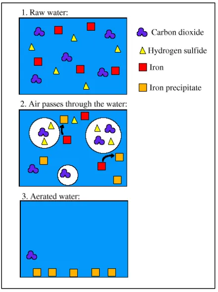
1.5 Concept Designs
Diffused air type will be used for this project where by a tube will be place in the middle at the bottom of the lake. Apart from that, there are branching structures of the main channel to the overall sides for aeration. A blower house will be located and equipped with two mechanical blowers which operate intermittently to provide air for aeration process. The blower operated automatically controlled by switch depends on BOD and COD of the water. The figure below shows the basic concept diffuse air that will be install at Tasik UTeM.
4
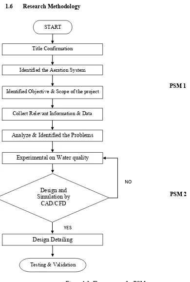
1.6 Research Methodology
Figure 1.3: Flow process for PSM START
Title Confirmation
Identified the Aeration System
Identified Objective & Scope of the project
Collect Relevant Information & Data
Analyze & Identified the Problems
Experimental on Water quality
Design and Simulation by
CAD/CFD -
PSM 1
PSM 2
YES
NO
Design Detailing
5
CHAPTER 2
LITERATURE REVIEW
2.0 BACKGROUND STUDY
Aeration is the process which area of the contact between water and air is increased, by natural or mechanical devices for oxygenation process. This process is the most efficient techniques frequently apply in the improvement of the physical and chemical properties and characteristics of water. The function of aeration improves the taste and odor of the water, such as lake and river by supplying the enough oxygen, rescuing the free carbon dioxide and eliminating much of the hydrogen sulfide and other odorous presents. Besides that, removal of iron and manganese from such oxygen deficient waters also usually requires aeration as an initial step. This initial step allows for the lower oxides of these minerals that are dissolved in the water and combined with carbon dioxide to be converted to higher insoluble oxides and in turn removed by subsequent sedimentation, contact or filtration. The benefit from aeration are:
Improve overall water quality. Increase the population of fish.
Cause circulation currents that might create favorable conditions for more desirable algae to out compete blue green algae.
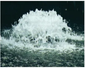
6 The efficiency of the aeration process depends on almost entirely on the amount of surface contact between the air and water. This contact is controlled primarily by the size of the water droplet or air bubbles. The goal of an aerator is to increase the surface area of water coming in contact with air so that more air can react with the water. As air or water is broken up into smaller drops/bubbles or into thin sheets, the same volume of either substance has a larger surface area. Figure 2.1 below shows the basic process of aeration
Figure 2.1: Basic Aeration Process
7 Oxidation is the other process through which aeration purifies water. Oxidation is the addition of oxygen, the removal of hydrogen, or the removal of electrons from an element or compound. When air is mixed with water, some impurities in the water, such as iron and manganese, become oxidized. Once oxidized, these chemicals fall out of solution and become suspended in the water. The suspended material can then be removed later in the treatment process through filtration.
2.1 TYPES OF AERATION SYSTEM
There are several types of aeration system used for wastewater treatment. The system used depends on the function to be performed, type and geometry of the reactor, and cost to install and operate the system.
2.1.1 Fountains Aerator
For this kind of aerator, it works very well in small pond and relatively shallow. Fountains improve a pond's aesthetic appeal and recirculate the water near the pond's surface. Fountains are generally ineffective because it does not recirculate the water near the bottom of the pond.
Figure 2.2: Fountain type aerator
8 pond, and the waves creates by the fountain should dissipate before reach the edge. This system is not efficient because energy is used to create the display.
2.1.2 Propeller Aerator
This propeller aerator was specially developed for intensive production of fish in tanks and ponds. This unit employs a float, motor, and prop to splash at the water surface with fairly decent oxygen transfer rate. The maintenance free, heavy duty, motor (230 or 380 Volt) with low power consumption (0.18-1.00 kW) has a mounted propeller which allows a high water circulation of up to 50-180 m3/h (splash height 60-90 cm and splash diameter 160-250 cm). The small float size, compact and lightweight system make it fast and easy to install. This aeration system is not efficient at moving water at deeper level.
Figure 2.3: Propeller Type Aerator
The following types are available as standard:
Table 2.1: Table indicates types available at standard
Power consumption kw/HP 0.18/0.2 0.37/0.5 0.75/1.0
Water circulation m3/h 50 100 180
Water splash Ø cm 160 180 250
Splash height cm 60 75 90