DOI: 10.12928/TELKOMNIKA.v13i4.1898 1263
Adaptive Fuzzy Sliding Mode Control for a Class of
Nonlinear System
Xue Xiao1, 2, Zheng3, Dong Haobin4,* 1
Institute of Geophysics and Geomatics, China University of Geosciences, Wuhan 430074, Hubei, China 2Electrical & Electronic Engineering Institue, Nanyang Institute of Technology, Nanyang 473004, Henan,
China
3Physics & Electronic Engineering College, Nanyang Normal University, Nanyang 473061, Henan, China 4
School of Automation, China University of Geosciences, Wuhan 430074, Hubei, China e-mail: [email protected]
Abstract
For a class of nonlinear system with parameter perturbation and external disturbance, adaptive fuzzy control can be used to approach the system unknown functions to reduce the control input and the steady-state error. And an adaptive switch control gain whose adaptive law is decreasing function is designed to weaken the system chattering, the switch gain of estimate will increase on the basis of the original without decreasing with the elimination of interference.If system is interferenced many times. Against the shortcomings, this paper proposes an improved adaptive law that can weaken the system chattering effectively while maintaining the strong robustness. The simulation results by tests show that this method is correct and effective.
Keywords: Adaptive Fuzzy Control, Integral Sliding Mode, Nonlinear System, Robustness
Copyright © 2015 Universitas Ahmad Dahlan. All rights reserved.
1. Introduction
As a control method for systems which retain strong robustness with the characteristics of parametric uncertainties and disturbance, sliding mode control technology is highlighted by control research. In order to achieve excellent control effect, many researchers apply various control theories to sliding mode control, such as adaptive sliding mode control [1-3], fuzzy sliding mode control [4] and neural network sliding mode control [5]. Tractor steering angle controller is designed through adaptive sliding mode control method in quotation [6]. Outstanding trajectory tracking and handling stability is obtained and the effects of parameter perturbations and external disturbances on the system operability can be overcome effectively [7]. Adaptive integral sliding mode is applied to systems with uncertain parameters and the effects of control are achieved successfully in quotation [8]. Feedback linearization method and posture control holder combining with variable sliding mode structure are designed based on differential geometry for heavy equipment airdrop process motion model with the characteristics of strong coupling, strong nonlinearity and large disturbance [9-12].
However, there is a problem in the above researches. The traditional adaptive law is non decreasing function, the uncertainty is estimated to increase in the original basis, not with the estimated value of disturbance and the disappearance of gradually decreasing, buffeting increased with the time prolonging. The method of dead time characteristic and adaptive law nonlinear characteristics in combination, can better solve the problem. The basic idea of the method is, in reaching mode of the traditional sliding mode control, adaptive law guarantee system can quickly reach the sliding surface; when the switching function value reaches the set value, the adaptive law to change, the switching function as the value of the switching gain, the sliding mode control of switching gain decreased with the decrease of switching function, the final driven by the steady system enters the sliding mode.
Jaap Andrianof direct method to prove the stability of the system, the simulation results show that, the improved method effectively weakening the adaptive law is non decreasing control input chattering, so that the system has good dynamic performance and robustness.
2. System Description and Integral type Sliding Mode Surface Design Considering the SISO nonlinear system
( , ) ( , ) ( )
x f x t g x t u t d t (1)
In the above formula, f x t( , ),g x t( , )are unknown nonlinear functions, and g x t( , ) 0,
( )
d t external interference.Defining the system tracking error ise t
x t
r t , using the system tracking error feedback build sliding mode surface
1
2
s t KE t e t k e t k e t So:
0 1
2
0
1
2
t t
s t e k e k e d x t r t k e k e d
(2)
Can be seen from the type (2), the system has constructed the integral sliding mode surface, the system tracking error depends on the state feedback matrix K
1, ,k k1 2
, by determining suitable k1and k2, the tracking error e t
will be close to zero, and the system will have a good dynamic performance.3. Design of an Adaptive Fuzzy Sliding Mode Controller 3.1. Algorithm Design
For type (1) nonlinear system, said if f x t( , ), g x t( , ) and d t( ) as is known, s t
s t
0 can be based on the sliding mode in the ideal state of the control law for the calculation of surface:
* 1
1 2
( , ) ,
u t g x t f x t d t r t k e t k e t (3)
If g(x,t)and d(t) is unknown, *
u t is difficult to achieve, and a fuzzy system approach *
u t is
used.
The switching function s t
is as the input of fuzzy controller, which forms a single input fuzzy approximation system, fuzzy rules, and the fuzzy controller for:Rule i:IF sis i s
F , THENu is i (4)
And i=1, , ,2 3 … m, ,iand i s
F are fuzzy sets; by centroid method to defuzzification the fuzzy controller output will be:
T Tf
1 1
, /
m
m z i i i
i i
u s (5)
And iis the i-th rule’s weight,
1, 2, 3,...,m
,
1, 2, 3,...,m
, i is defined to be:1
/
mi i i
i
On the basis of fuzzy approximation theory, there is an optimal fuzzy system
*
fz ,u s that can
approachu*
t .
* * * T
fz , ( )
u t u s (7)
And the is approximate error that meets ||D.If fuzzy system ufz approaches u*
t , so
Tfz ,ˆ ˆ
u s (8)
And ˆis the estimated value of *
.The switching control law to compensate the error between switching control law robustness, strong on the approximation error, defined as the switching control law:
vs sgn
u t s t (9)
So the total control rule of system (1) is :
fz vsu t u u
(10)
In the switching controller, because of the uncertain parameters of the system and the existence of interference, resulting in the switching gain
t is difficult to determine, the actual control todetermine, if
t the value selected is too large, will produce buffeting larger, if too small, robust system decline and tend to be unstable. In order to reduce the amount of calculation can be used to control system from the law of use to design
t , definition:
vs ˆ sgn
u t s t (11)
2
ˆ
t s t (12)
ˆ
t is the switch gain of estimate, 2 is the adaptive factor of the real number to characterizethe speed of the adaptive law with speed. The adaptive estimation error can be defined as:
ˆ
t t D (13)
Define ˆ *, so formula (7) can be transformed as:
* * T
f ˆf ˆf f
z z z z
u u u u u (14)
Put formula (2) into formula (3), and can get:
1 *
1
, ,
, ,
u t g x t f x t d t r t e t s t
g x t g x t u t s t
(15)
So:
*
*
f vs
, ,
z
3.2. The Stability Proof Define Lyapunov function as:
2
21 2
, ,
0.5
2 2
g x t T g x t
V t s t t
So:
1 2 * f 1 2 T 1 2 T vs 1 2 T 1 2 , , , , , , , , , ˆ ˆ , , , ˆ , T T z Tg x t g x t
V t s t s t t t
g x t g x t
s t g x t u u t t t
g x t g x t
s t g x t t t
g x t
g x t s t s t g x t u t D t
g x t
g x t s t
t D
ˆ
t ˆ t s t g x t, s t g x t
,(17)
For system stability, fuzzy approximation coefficient estimation using the following algorithm
1ˆ
s t (18)
Put the type (12) and (18) into type (17), available:
ˆ , , ˆ , , , , , , 0 V t t s t g x t s t g x t t D s t g x t
s t g x t D s t g x t s t g x t D s t g x t
D s t g x t
(19)
Because the type (12) characterization of the adaptive estimation law is non decreasing function, namely the adaptive law ˆ
t does not change with the weakening or disturbance, can only increase in the original basis, and the actual system subject to disturbances or parameter is variable, with the extension of time, the switching adaptive law is decided by the control will be more and more large, chattering will strengthen. In order to reduce buffeting strength system, the method of adaptive law is used.3.3. Improved Adaptive Control Law
Here draw on the experience of method of the nonlinear characteristics of dead zone to design adaptive law to improve the formula (12) such as follows:
2 ˆ , ˆ , t s t s
t s n s (20)
Here 0,n0. The theoretical analysis is as follows:
(b) When the state of the system, has returned to the sliding surface, a modified adaptive law to control, can make the switch gain decreased with the decrease of the error. The stability proof:
The Lyapunov function
2
1
, 0.5
2
g x t T
V t s t (21)
By formula (17) and (18) available:
T
1 vs
2
, / ,
ˆ
, sgn
, sgn sgn
,
V t g x t s t s t g x t u
s t g x t t s t
s t g x t s t s t n s t
g x t s t n s t s t
(22)
The approximation error goes to zero, so the type (22) with the following changes:
2
2
, , 0
V t g x t s t n s t s t g x t s t n s t (23)
(c) Multiple disturbance by the system, changes in the system error performance in S. Error increase or decrease S will be in (a) and (b) the boundary line and switching of two state representation, eventually drove converge to zero, switching estimation value of control gain also decreased.
(d) In the adaptive law expression (20), determining the gain of switch control the speed of change, is beneficial for the system to uncertain interference suppression, on the other hand, takes a long time to suppress the disturbance. For a small positive number, can converge into the sliding mode to ensure system. As a boundary value.
4. Verification and Simulation Analysis
Based on the tracking error state feedback integral sliding mode surface, use the following 5 kinds of membership function of fuzzy:
2exp / 6 / / 24
NM s s (24)
2exp / 12 / / 24
NS s s (25)
2exp / / 24
ZO s s (26)
2exp / 12 / / 24
PS s s (27)
2exp / 6 / / 24
PM s s (28)
1 2
2
1 2 1 1 1
2 2 2
1 1
sin cos sin / cos /
4 / 3 cos / 4 / 3 cos /
c c
c c
x x
g x mlx x x m m x m m
x u t d t
l m x m m l m x m m
(29)
And in (29) x1 is swing angle and x2 is swing speed, 2
9.8m /
g s ,mc 1kgvehicle qualitym0.1kgas the pendulum rod qualityl0.5mhalf the length of pendulumas the control input. Follow the sinusoidal signal, the position command, the initial state of the system, when the system is: interference; follow the step signal, the initial state is applied for 0 seconds, the interference of 0.2 seconds.
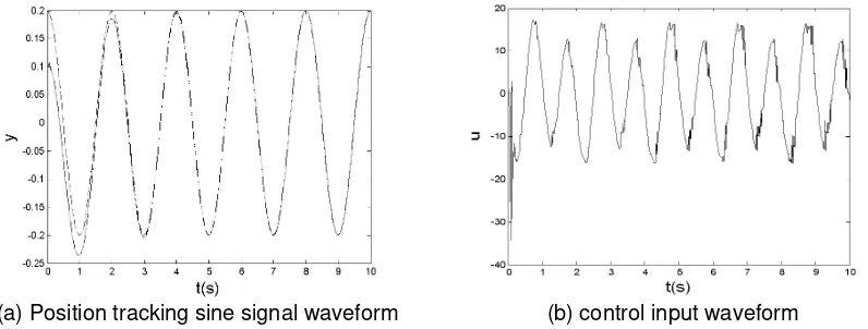
The control law by type (10), (18) and (20), the controller parameters 1 1000, 2 10, 0.01
,n1 the simulation curve as shown fromFigure 1 to 3.
[image:6.595.98.496.267.418.2](a) Position tracking sine signal waveform (b) control input waveform
Figure 1. Sinusoidal signal system to follow and control the input waveform
(a) The conventional method processing stepwaveform signal tracking
(b) The improved method processing step waveform signal tracking
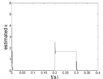
[image:6.595.107.500.467.627.2](a) Adaptive parameter conventional waveform
[image:7.595.317.491.90.224.2](b) Adaptive parameters improved waveform
Figure 3. Adaptive trajectory
5. Conclusion
Based on the analysis of the adaptive law of traditional adaptive fuzzy sliding mode control method is overcome, improving method is put forward. The nonlinear characteristics of applied to the adaptive law, effectively solve the adaptive law is non decreasing defects. Simulation results show that the improved method is correct and effective. While maintaining the original adaptive fuzzy sliding mode control based on advantage of suppressing disturbance, new method obviously weaken the chattering, reduces the control input, and achieve the adaptive law to estimate the parameters change with the disturbance changes, effectively solves the problems of the previous methods.
References
[1] Shui-Chun Li, Cing-Chich Tsai, Hsu-Chih Huang. Nonlinear Adaptive Sliding-Mode Control Design for Two-Wheeled Human Transportation Vehicle. Proceedings of IEEE International Conference on Systems, Man and Cybernetics (SMC 2009). 2009, 1965-1970.
[2] Farzin Piltan. Design Gradient Descent Optimal Sliding Mode Control of Continuum Robots. IAES International Journal of Robotics and Automation. 2012, 1(4): 175-189.
[3] Gouichiche Abdelmadjid, Boucherit Mohamed Seghir, Safa Ahmed, Messlem Youcef. Sensorless Sliding Mode Vector Control of Induction Motor Drives. International Journal of Power Electronics and Drive Systems. 2012, 2(3): 277-284.
[4] Haitao Liu, Tie Zhang. Fuzzy Sliding Mode Control of Robotic Manipulators with Kinematic and Dynamic Uncertainties. Journal of Dynamic Systems, Measurement and Control. 2012, 134(6): 061007 (Article number).
[5] Huang SJ, Huang KS, Chiou KC. Development and application of a novel radial basis function sliding mode controller. Mechatronics. 2003, 13(4): 313-329.
[6] Zhou Lijie, Wang Nengjian, Zhang Defu. Adaptive sliding mode of tractor aircraft system. Control theory and application. 2012, 29 (4): 529-534.
[7] Wenlong Song, Yaqiu Liu, Lipiing Sun. Model Reference Adaptive Integral-type Sliding Mode Control Design for a class of Uncertain Systems. Proceeding of the 6th World Congress on Intelligent Control and Automation. 2006: 2056-2060.
[8] Li Dadong, Sun Xiuxia, Dong Wenhan, Xu Guangzhi. A sliding mode variable structure heavy equipment airdrop longitudinal control law design based on feedback linearization. Control theory and applications. 2013, 30 (1): 54-60.
[9] Liu Wenjiang, Sui Qingmei, Zhou Fengyu, Xiao Hairong. Adaptive fuzzy sliding mode control for ship course controller design based on. Information and control. 2012, 41(2): 136-141.
[10] Huo long, Le Guigao, Ma Dawei, Hu Jian. The application of adaptive fuzzy sliding mode in the position servo system of rocket launcher. Fire and command control. 2012. 37(9): 137-140.
[11] Liu Yunfeng, Peng Yunhui, Yang Xiaogang, Miao Dong. Fuzzy sliding mode control of adaptive nonlinear systems based on high gain observer. Systems engineering and electronics. 2009, 31(7): 1723-1727.