DOI: 10.12928/TELKOMNIKA.v15i1.3484 150
High Sensitivity Very Low Frequency Receiver for
Earthquake Data Acquisition
Achmad Munir*1, Kusmadi2, Kusnandar3, Asep Najmurrokhman4, Chairunnisa5, Sunubroto6
1,2,5Radio Telecommunication and Microwave Laboratory, School of Electrical Engineering and Informatics,
Institut Teknologi Bandung, Jalan Ganesha 10 Bandung, 40132, Indonesia, Phone: +62-22-2501661
3,4,6Department of Electrical Engineering, Faculty of Engineering, Universitas Jenderal Achmad Yani,
Jalan Terusan Jendral Sudirman, Cimahi, 40633, Indonesia, Phone: +62-22- 6656190 *Corresponding author, e-mail: [email protected]
Abstract
A high sensitivity very low frequency (VLF) receiver is developed based on AD744 monolithic operational amplifier (Op-Amp) for earthquake data acquisition. In research related natural phenomena such as atmospheric noise, lightning and earthquake, a VLF receiver particularly with high sensitivity is utterly required due to the low power of VLF wave signals received by the antenna. The developed receiver is intended to have high sensitivity reception for the signals in frequency range of 10-30kHz allocated for earthquake observation. The VLF receiver which is portably designed is also equipped with an output port connectable to the soundcard of personal computer for further data acquisition. After obtaining the optimum design, the hardware realization is implemented on a printed circuit board (PCB) for experimental characterization. It shows that the sensitivity of realized VLF receiver is almost linear in the predefined frequency range for the input signals lower than -12dBm and to be quadratic for the higher level input signals.
Keywords: data acquisition, earthquake, high sensitivity, VLF receiver
Copyright © 2017 Universitas Ahmad Dahlan. All rights reserved.
1. Introduction
Very low frequency (VLF) waves due to their wavelength can diffract around large obstacles and can propagate as ground waves following the curvature of the earth. VLF waves which also preferred as myriametre waves are, in general, produced by a variety of natural phenomena. Atmospheric noise, lightning, and earthquake are some of the phenomena that dominantly generate VLF waves in nature where the impulses travel at the distance along the magnetic field lines of earth from one hemisphere area to the other [1]. VLF waves can also be man-made generated using electronic devices for numerous applications such as for government radio station and military communication [2]. Some radio transmitters operate using VLF waves around frequency range of 15-30kHz are used mainly for marine navigation, communication with submersed submarines, and other research purposes [2-3]. A recent research related underwater sensor network (UWSN) has been reported by employing VLF of 7kHz as a carrier frequency [4]. Meanwhile, the use of VLF waves has also been implemented to characterize the subsurface of earth in some region and to control the ultrasonic motor through the pulse width modulation control method [5-6]. Some research projects that use VLF waves which has been recently investigated intensively are Atmospheric, Weather, Electromagnetics System for Observation, Modeling, and Education (AWESOME) and Sudden Ionospheric Disturbance (SID) [7-11].
designed for earthquake data acquisition. The VLF receiver which is intended to operate at frequency range of 10-30kHz is developed from the previous work based on a high sensitivity AD744 monolithic operational amplifier (Op-Amp) as a main component to achieve the requirement [11]. Two frequencies of VLF transmitters spread around the world which are frequently used in research of VLF waves associated with earthquake, i.e. VTX transmitter at India works at frequency of 18.2kHz and NWC transmitter at Australia operates at frequency of 19.8kHz, will be used as a basis on the development of VLF receiver. Furthermore, the VLF receiver is also expected to produce high gain output signal along the desired frequency range. Therefore, sensitivity and gain will be paid more attention in the development process. In addition, the VLF receiver is also designed to be portable and connectable to the soundcard of personal computer for data acquisition process.
2. Design of VLF Receiver
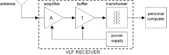
In general, as shown in block diagram of Figure 1, the input VLF signals radiated from some VLF transmitters are received by the antenna. Since the level of received signals is almost in few microwatts or less, hence a VLF receiver should possess high sensitivity and high gain characteristic to process the received signals to have an acceptable level for further processing. The output signals are supposed to be buffered before being transformed into a specific signal required by personal computer for data acquisition process. In most cases, there are several parameters of VLF receiver that should be taken into account in the design process including gain, linearity, sensitivity and noise figure. However, among those parameters, sensitivity and gain will be paid more attention due to their important roles in determining the performance of VLF receiver.
Figure 1. Block diagram of VLF receiver for earthquake data acquisition
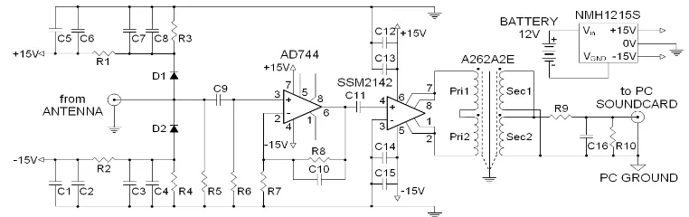
Figure 2. Schematic Diagram of VLF Receiver Developed using an AD744 Monolithic Op-Amp
As shown in Figure 2, VLF signals from antenna is coupled through C9 and amplified using a voltage follower of AD744 amplifier in which the gain of amplifier is determined from the ratio of R8 and R7 as expressed in Equation (1). In this case, C9 also acts as a highpass filter together with R6 to avoid interferences from the dc current. A pair of D1 and D2 is connected to the RC filter to protect the amplifier from surge voltages coming from input signals. A stable operation of amplifier with external compensation for a capacitive loading is achieved by connecting C10 in parallel with R8. The recommended values of R7, R8 and C10 along with expected slew rate and bandwidth for various gain and load are tabulated in Table 2 [16].
7
Table 1. Value of Each Component for VLF Receiver Diodes Resistors Capacitors
3. Realization and Characterization
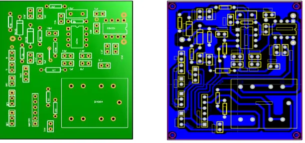
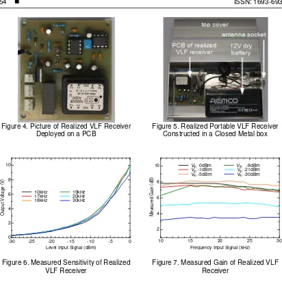
From the optimum result of design, the prototype is then realized on a printed circuit board (PCB) for experimental characterization. The layout diagram of PCB which is constructed based on the schematic diagram and its components placement are shown in Figure 3. Meanwhile, Figure 4 shows the picture of realized VLF receiver deployed on a PCB with the dimension of 64mm (length) x 56.7mm (width). To obtain the construction of VLF receiver portably, all parts of receiver including a dc 12V dry battery, PCB, wiring cables, switches and sockets for personal computer are placed in a closed metal box as shown in Figure 5. The metal box takes the dimension of 160mm (length) x 96mm (width) x 53mm (height). Finally, the experimental characterization is performed using a signal generator and a spectrum analyzer to characterize some parameters of realized VLF receiver including sensitivity and gain in the frequency range of 10-30kHz. It is noticeable that the frequency range above is chosen to match the real application.
Figure 3. Layout Diagram of PCB based on Schematic Diagram and its Components Placement; Top Layer (left); Bottom Layer (right)
Figure 4. Picture of Realized VLF Receiver
Meanwhile form the measured gain plotted in Figure 7, the gain performance of realized VLF receiver has satisfied the requirement for frequency range of 10-30kHz with the maximum gain of 8dB for the input signal around -5dBm. It shows that the measured gain tends to be linear for the input signal above than -8dBm and lowers for the input signal less than -8dBm. This is in contrast with the measured sensitivity for the same range of input signal which is probably evoked by the characteristic of Op-Amp itself. Although there is some fluctuation of output signal in the frequency range below 15kHz for the input signal of -8dBm, in general the gain of realized amplifier is almost flat for various frequency ranges of input signal. Therefore, from the measured results of sensitivity and gain, it can be inferred that the realized VLF receiver is implementable to process the received VLF signals.
4. Conclusion
[3] Chakrabarti SK. Propagation Affects of Very Low Frequency Radio Waves. Proceedings of the 1st International Conference on Science with Very Low Frequency Radio Waves: Theory and Observations. New York: American Institute of Physics. 2010.
[4] Bahrami N, Khamis NHJ, Baharom A, Yahya A. Underwater Channel Characterization to Design Wireless Sensor Network by Bellhop. TELKOMNIKA. 2016; 14(1).
[5] Purwanto EH, Minarto E, Bahri AY. Aplikasi Metode Very Low Frequency Electromagnetic (VLF-EM) untuk Karakteristik Bawah Permukaan di Daerah Kapur Desa Melirang Kecamatan Bungah Kabupaten Gresik. Jurnal Fisika Indonesia. 2015; 19(56): 38-41.
[6] Jingzhuo S, Caixia Z. Low-Frequency Pulse Width Modulation Control Methods of Ultrasonic Motor.
TELKOMNIKA. 2013; 11(9): 5150-5160.
[7] Scherrer D, Cohen M, Hoeksema, Inan U, Mitchell R, Scherrer P. Distributing Space Weather Monitoring Instruments and Educational Materials Worldwide for IHY 2007: The AWESOME and SID Project. Advances in Space Research. 2008: 42; 1777-1785.
[8] Cohen MB, Inan US, Paschal EW. Sensitive Broadband ELF/VLF Radio Reception With the AWESOME Instrument. IEEE Transactions on Geoscience and Remote Sensing. 2010; 48(1): 3-17. [9] Singh R, Veenadhari B, Cohen MB, Pant P, Singh AK, Maurya AK, Vohat P, Inan US. Initial Results
from AWESOME VLF Receivers: Set Up in Low Latitude Indian Regions under IHY2007/UNBSSI Program. Current Science. 2010; 98(3): 398-405.
[10] Putera R, Kusnandar, Najmurrokhman A, Sunubroto, Chairunnisa, Munir A. High Gain RF Amplifier for Very Low Frequency Receiver Application. Proceeding of 6th International Conference on Information Technology and Electrical Engineering (ICITEE). Yogyakarta. 2014: 199-202.
[11] Kusnandar, Kusmadi, Najmurrokhman A, Sunubroto, Chairunnisa and Munir A. Development of High Sensitivity Amplifier for VLF Receiver Application. Proceeding of 5th International Conference on Electrical Engineering and Informatics (ICEEI). Denpasar. 2015: 328-331.
[12] Hayakawa M, Kasahara Y, Nakamura Y, Hobara Y, Rozhnoi A, Solovieva M, Molchanov OA. On The Correlation Between Ionospheric Perturbations as Detected by Subionospheric VLF/LF Signals and Earthquakes as Characterized by Seismic Intensity. Journal of Atmospheric and Solar-Terrestrial
Physics. 2010; 70: 982-987.
[13] Brijraj S, Collier AB. Investigation of Anomalous Perturbations in VLF Signals and Correlation with Seismic Activity. Proceeding of XXXth URSI General Assembly and Scientific Symposium (URSI GASS). Istanbul. 2011: 1-4.
[14] Biagi PF, Righetti F, Maggipinto T, Schiavulli L, Ligonzo T, Ermini A, Moldovan IA, Moldovan AS, Silva HG, Bezzeghoud M, Contadakis ME, Arabelos DN, Xenos TD, Buyuksarac A. Anomalies Observed in VLF and LF Radio Signals on the Occasion of the Western Turkey Earthquake (Mw = 5.7) on May 19, 2011. International Journal of Geosciences. 2012; 3(4A): 856-865.
[15] Mullayarov V, Druzhin G, Argunov V, Abzaletdinova L, Mel’nikov A. Variations of VLF Radio Signals and Atmospherics During The Deep Earthquake With M = 8.2 Occurred on 24 May 2013 Near Kamchatka Peninsula. Natural Science. 2014; 6(3): 144-149.
[16] Analog Devices. Precision, 500ns Settling BiFET Op Amp. AD744 Datasheet. Rev. C. 2000. [17] Analog Devices. Balanced Line Driver. SSM2142 Datasheet. Rev. C. 2011.